Language selection

Search

Patent 1287727 Summary

Third-party information liability

Some of the information on this Web page has been provided by external sources. The Government of Canada is not responsible for the accuracy, reliability or currency of the information supplied by external sources. Users wishing to rely upon this information should consult directly with the source of the information. Content provided by external sources is not subject to official languages, privacy and accessibility requirements.

Claims and Abstract availability

Any discrepancies in the text and image of the Claims and Abstract are due to differing posting times. Text of the Claims and Abstract are posted:

  • At the time the application is open to public inspection;
  • At the time of issue of the patent (grant).
(12) Patent: (11) CA 1287727
(21) Application Number: 1287727
(54) English Title: INSULATED WALL ASSEMBLY
(54) French Title: MONTAGE DE MUR THERMO-ISOLANT
Status: Term Expired - Post Grant
Bibliographic Data
(51) International Patent Classification (IPC):
  • E04B 1/62 (2006.01)
  • E04B 2/70 (2006.01)
  • E04B 2/74 (2006.01)
  • E04B 2/80 (2006.01)
(72) Inventors :
  • DETTBARN, RICHARD (Canada)
(73) Owners :
  • NASCOR INCORPORATED
(71) Applicants :
  • NASCOR INCORPORATED (Canada)
(74) Agent:
(74) Associate agent:
(45) Issued: 1991-08-20
(22) Filed Date: 1987-06-01
Availability of licence: N/A
Dedicated to the Public: N/A
(25) Language of filing: English

Patent Cooperation Treaty (PCT): No

(30) Application Priority Data: None

Abstracts

English Abstract


ABSTRACT OF THE DISCLOSURE
An insulated wall assembly which combines strength
with good insulating qualities includes spaced apart, elongated
wooden posts, which are I-shaped in cross section; and elongated
rigid foam plastic panels extending between adjacent posts, the
panels being generally cruciform in cross section so that pro-
jections on the lateral edges thereof extend into the recesses
of the posts while the front and rear or outer and inner
surfaces of the panels are in the same planes as the outer and
inner surfaces of the posts. Alternatively, the panels are
parallelepipedic blocks with longitudinally extending, rectangular
grooves in the sides thereof for receiving splines, which
connect the blocks to rectangular, grooved insulating inserts
in the posts.


Claims

Note: Claims are shown in the official language in which they were submitted.

THE EMBODIMENTS OF THE INVENTION IN WHICH AN EXCLUSIVE
PROPERTY OR PRIVILEGE IS CLAIMED ARE DEFINED AS FOLLOWS:
1. An insulated wall assembly comprising spaced
apart wooden post means of I-shaped cross section; and insulating
panel means extending between and interconnecting said post means,
said panel means including lateral projections for insertion
into the recesses in said post means and front and rear surfaces,
which in the assembled condition define inner and outer surfaces of
the wall assembly.
2. A wall assembly according to claim 1, wherein
said panel means is substantially cruciform in cross section,
and including lateral projections for insertion into the recesses
in the post means.
3. A wall assembly according to claim 1, wherein
said panel means includes a grooved centre portion of rectangular
cross section for insertion between adjacent post means, grooved
inserts integral with the recesses in said post means; and spline
means for connecting said centre portion to said inserts to
complete the wall assembly.
4. A wall assembly according to claim 1, 2 or 3,
wherein at least one post means defines each end of the assembly,
the assembly including plug means in each post means at each
outer end of the assembly.
5. A wall assembly according to claim 1, 2 or 3,
wherein a pair of interconnected post means define one end of
one wall, and a single post means defines one end of a second
wall perpendicular to abuting one surface of the pair of post
means for defining a corner.
- 6 -

Description

Note: Descriptions are shown in the official language in which they were submitted.


~8~7~
This invention relates to a wall assembly, and in
particular to an insulated wall assembly.
Canadian Patents Nos. 1,116,371, issued to Truefoam
Canada Limited on January 19, 1982 and 1,12~82, issued to
Cano Thermo Systems Inc. on June 1, 1982 and applicant's
Canadian Patent Registration NO. 12~1815 issued September
13, 1988 describes insulated wall assemblies. The earlier
struct~res permit the construction of well insulated walls,
but, in general, require a large number of different parts
or components, particularly when forming corners.
An object of the present invention is to provide a
relatively simple insulated wall assembly, which while
structurally strong, requires few basic, lightweight
components.
An object of the present invention is to provide a
relatively simple insulated wall assembly, which while
structurally strong, requires few basic, lightweight
components.
Another object of the invention is to provide an
assembly of the above described type which is at least
approximately equal to earlier structures in terms of
insulating ability and the prevention of thermal bridging.
Accordingly, the present invention relates to an
insulated wall assembly comprising spaced apart wooden post
means of I-shaped cross section and insulating panel means
extending between and interconnecting said post means, said
panel means including lateral projections for insertion
into the recesses in said post means and front and rear
surfaces~ which in the assembled condition define inner and
outer surfaces of the wall assembly.
- 1 -

87~
The invention will be described in greater detall
with reference to the accompanyinq drawings, which illustrate
preEerred embodiments of the 1nvention, and wherein:
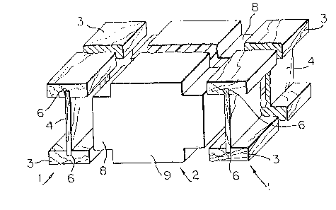
Figure l is an exploded, perspective view Erom one
end of a first embodiment oE a wall assembly in accordance
with the present invention;
Figure 2 is an exploded, perspective view of a
second embodiment of the wall assembly of the present invention;
Figure 3 is an exploded, perspective view of all of
the elements required to form a wall assembly of the type
shown in Fig. l;
Figure 4 is an exploded, per~pective view of all of
the elements required to form a wall assembly of the type shown
in Fig. 2;
Figure 5 is a plan view of one corner of a wall assembly
constructed with the elements of Fig. 3;
Figure 6 is a plan view of one corner of a wall
assembly constructed with the elements of Fig. ~; and
Figure 7 is a side elevation view of a wall assembly
of the type shown in Fig. 5 or 6.
Referring to Fig. 1, the basic elements of a wall
assembly in accordance with the present invention include an
I-beam type or I-shaped post yenerally indicated at 1 and a
rigid foam plastic insulating panel generally indicated at 2.
The post l does not embody a new s-tructure, i.e. posts of this

727
type are known. However, it is helieved -that such posts have
not been employed in the manner proposed herein. ~`ach post 1
is defined by a pair of spaced apart 2" x 6" spruce planks or
boards 3 wh:ich are interconnected by a narrow wooden web 4 oE
plywood. The web 4 ex-tends into rectangular, lonyi-tudinally
extending grooves 6 in the boards 3. The web 4 is glued to
the boards 3.
The boards 3 and web 4 define rectangular recesses
for receiving lateral projections 8 on the insulating panel 2.
The panel 2 is defined by a rigid foam plastic body 9 of cruci-
form cross section. The foam plastic is expanded polystyrene.
By using a cruciform cross section with the lateral projections
8, the body 9 can be used to interconnect adjacent pos-ts 1, the
projections 8 extending into aligned recesses in the posts.
Referring to Fig. 2 a second embodiment of the invention
includes -the posts 1, which have been modified to include
insulating inserts 10, and a rigid foam plastic panel generally
indicated at 12. The inserts 10 are integral with the posts 1
and include rectangular, longitudinally extending grooves 14
in the centre of the outer, side edge thereof for receiving
a rigid foam plastic spline 15 (Figs. 4 and 6). The panel 12
is basically a rectangular parallelepipedic block or body 16
with rectangular, longitudinally extending grooves 17 in the
centre of each side thereof for receiving splines 15. As shown
in Figs. 3 and 4, -the panel 9 or 16 can include a transversely

~ ~7727
e~tending groove 18 Eor carrying electrical wires.
A corner in a wall assembly producecl using the posts 1
and panels 2 of F`ig. 1 requires only one additional element,
namely a rectangular insulating plug 19 (Fig. 3), which is
inserted into an outer groove in the post 1. By the same token,
the posts 1 and panels 12 of Fig. 2 recluire only a plug 18 for
completing a corner structure.
With reference to Fig. 5, a wall assembly constructed
with the elements of Figs. 1 and 3 includes posts 1 and panels
2 which arestrung together to form walls of the desired length.
A plug 19 is inserted into each end of each wall to complete the
wall. In each case, the plug 19 adds insulation and provides a
smooth end. When forming a corner a spline 15, a second end
post 1 and a plug 19 are added to a first wall, and the post
1 of the second perpendicular wall abuts the inner surface of
the outer post 1 and a portion of -the inner post 1 of such
first wall. As shown in Fig. 6, essentially the same elements
are used to form a wall assembly with a corner when employing
the elements of Figs. 2 and 4.
A complete wall (Fig. 7) is produced using a top
plate 20, a bottom plate 21, posts 1 and panels 2. In order
to form a window opening 23, a lintel 25 is inserted between
two posts 1. The lintel 25 is supported by end posts 26.
A short pos-t 28 and short panels 29 are provided beneath the
lintel, and a sill 30 is at-tached to -the tops of the post 28
and -the panels 29.

727
Thus, there has been descrlbed a relatively simple
wall assembly, which i.s formed usin~ a small number of
elements, and whichisstructurally sound.

Representative Drawing
A single figure which represents the drawing illustrating the invention.
Administrative Status

2024-08-01:As part of the Next Generation Patents (NGP) transition, the Canadian Patents Database (CPD) now contains a more detailed Event History, which replicates the Event Log of our new back-office solution.

Please note that "Inactive:" events refers to events no longer in use in our new back-office solution.

For a clearer understanding of the status of the application/patent presented on this page, the site Disclaimer , as well as the definitions for Patent , Event History , Maintenance Fee  and Payment History  should be consulted.

Event History

Description Date
Inactive: Expired (old Act Patent) latest possible expiry date 2008-08-20
Inactive: Late MF processed 2007-10-31
Letter Sent 2007-08-20
Inactive: IPC from MCD 2006-03-11
Inactive: Late MF processed 2005-11-10
Letter Sent 2005-08-22
Inactive: Late MF processed 2003-10-02
Inactive: Office letter 2003-09-17
Letter Sent 2003-08-20
Inactive: Office letter 2001-06-20
Change of Address Requirements Determined Compliant 2001-06-20
Grant by Issuance 1991-08-20
Small Entity Declaration Determined Compliant 1987-06-01

Abandonment History

There is no abandonment history.

Fee History

Fee Type Anniversary Year Due Date Paid Date
MF (category 1, 6th anniv.) - small 1997-08-20 1997-06-09
MF (category 1, 7th anniv.) - small 1998-08-20 1998-06-19
MF (category 1, 8th anniv.) - small 1999-08-20 1999-08-09
MF (category 1, 9th anniv.) - small 2000-08-21 2000-06-16
MF (category 1, 10th anniv.) - small 2001-08-20 2001-06-26
MF (category 1, 11th anniv.) - small 2002-08-20 2002-08-01
Reversal of deemed expiry 2007-08-20 2003-09-02
MF (category 1, 12th anniv.) - small 2003-08-20 2003-09-02
MF (category 1, 13th anniv.) - small 2004-08-20 2004-07-30
MF (category 1, 14th anniv.) - small 2005-08-22 2005-11-10
Reversal of deemed expiry 2007-08-20 2005-11-10
MF (category 1, 15th anniv.) - small 2006-08-21 2006-06-28
MF (category 1, 16th anniv.) - small 2007-08-20 2007-10-31
Reversal of deemed expiry 2007-08-20 2007-10-31
Owners on Record

Note: Records showing the ownership history in alphabetical order.

Current Owners on Record
NASCOR INCORPORATED
Past Owners on Record
RICHARD DETTBARN
Past Owners that do not appear in the "Owners on Record" listing will appear in other documentation within the application.
Documents

To view selected files, please enter reCAPTCHA code :


To view images, click a link in the Document Description column. To download the documents, select one or more checkboxes in the first column and then click the "Download Selected in PDF format (Zip Archive)" or the "Download Selected as Single PDF" button.

List of published and non-published patent-specific documents on the CPD .

If you have any difficulty accessing content, you can call the Client Service Centre at 1-866-997-1936 or send them an e-mail at CIPO Client Service Centre.


Document
Description 
Date
(yyyy-mm-dd) 
Number of pages   Size of Image (KB) 
Cover Page 1993-10-21 1 10
Claims 1993-10-21 1 34
Drawings 1993-10-21 2 60
Abstract 1993-10-21 1 23
Descriptions 1993-10-21 5 130
Representative drawing 2002-01-11 1 16
Notice: Maintenance Fee Reminder 1998-05-21 1 119
Notice: Maintenance Fee Reminder 1999-05-25 1 120
Notice: Maintenance Fee Reminder 2000-05-24 1 119
Notice: Maintenance Fee Reminder 2001-05-23 1 119
Notice: Maintenance Fee Reminder 2002-05-22 1 119
Notice: Maintenance Fee Reminder 2003-05-21 1 115
Maintenance Fee Notice 2003-09-17 1 174
Late Payment Acknowledgement 2003-10-20 1 166
Notice: Maintenance Fee Reminder 2004-05-25 1 117
Notice: Maintenance Fee Reminder 2005-05-24 1 118
Maintenance Fee Notice 2005-10-17 1 173
Late Payment Acknowledgement 2005-11-17 1 166
Notice: Maintenance Fee Reminder 2006-05-24 1 118
Notice: Maintenance Fee Reminder 2007-05-23 1 120
Maintenance Fee Notice 2007-10-01 1 173
Late Payment Acknowledgement 2007-11-13 1 164
Correspondence 2003-09-17 1 24
Fees 2003-09-02 1 58
Fees 2003-10-02 1 41
Fees 1999-08-09 2 166
Fees 2000-06-16 1 25
Fees 1998-06-19 2 211
Correspondence 2001-06-20 2 38
Fees 2001-06-26 2 210
Fees 2002-08-01 2 123
Fees 1997-06-09 1 38
Fees 1997-09-23 4 100
Fees 2004-07-30 1 56
Fees 2005-11-10 2 59
Fees 2006-06-28 4 129
Fees 2007-10-31 4 190
Fees 1993-06-22 1 30
Fees 1996-06-11 1 35
Correspondence 1997-01-10 2 33
Correspondence 1996-12-23 1 36
Fees 1995-08-15 1 40
Fees 1994-08-16 1 43