Sélection de la langue

Search

Sommaire du brevet 1287727 

Énoncé de désistement de responsabilité concernant l'information provenant de tiers

Une partie des informations de ce site Web a été fournie par des sources externes. Le gouvernement du Canada n'assume aucune responsabilité concernant la précision, l'actualité ou la fiabilité des informations fournies par les sources externes. Les utilisateurs qui désirent employer cette information devraient consulter directement la source des informations. Le contenu fourni par les sources externes n'est pas assujetti aux exigences sur les langues officielles, la protection des renseignements personnels et l'accessibilité.

Disponibilité de l'Abrégé et des Revendications

L'apparition de différences dans le texte et l'image des Revendications et de l'Abrégé dépend du moment auquel le document est publié. Les textes des Revendications et de l'Abrégé sont affichés :

  • lorsque la demande peut être examinée par le public;
  • lorsque le brevet est émis (délivrance).
(12) Brevet: (11) CA 1287727
(21) Numéro de la demande: 1287727
(54) Titre français: MONTAGE DE MUR THERMO-ISOLANT
(54) Titre anglais: INSULATED WALL ASSEMBLY
Statut: Durée expirée - après l'octroi
Données bibliographiques
Abrégés

Abrégé anglais


ABSTRACT OF THE DISCLOSURE
An insulated wall assembly which combines strength
with good insulating qualities includes spaced apart, elongated
wooden posts, which are I-shaped in cross section; and elongated
rigid foam plastic panels extending between adjacent posts, the
panels being generally cruciform in cross section so that pro-
jections on the lateral edges thereof extend into the recesses
of the posts while the front and rear or outer and inner
surfaces of the panels are in the same planes as the outer and
inner surfaces of the posts. Alternatively, the panels are
parallelepipedic blocks with longitudinally extending, rectangular
grooves in the sides thereof for receiving splines, which
connect the blocks to rectangular, grooved insulating inserts
in the posts.

Revendications

Note : Les revendications sont présentées dans la langue officielle dans laquelle elles ont été soumises.


THE EMBODIMENTS OF THE INVENTION IN WHICH AN EXCLUSIVE
PROPERTY OR PRIVILEGE IS CLAIMED ARE DEFINED AS FOLLOWS:
1. An insulated wall assembly comprising spaced
apart wooden post means of I-shaped cross section; and insulating
panel means extending between and interconnecting said post means,
said panel means including lateral projections for insertion
into the recesses in said post means and front and rear surfaces,
which in the assembled condition define inner and outer surfaces of
the wall assembly.
2. A wall assembly according to claim 1, wherein
said panel means is substantially cruciform in cross section,
and including lateral projections for insertion into the recesses
in the post means.
3. A wall assembly according to claim 1, wherein
said panel means includes a grooved centre portion of rectangular
cross section for insertion between adjacent post means, grooved
inserts integral with the recesses in said post means; and spline
means for connecting said centre portion to said inserts to
complete the wall assembly.
4. A wall assembly according to claim 1, 2 or 3,
wherein at least one post means defines each end of the assembly,
the assembly including plug means in each post means at each
outer end of the assembly.
5. A wall assembly according to claim 1, 2 or 3,
wherein a pair of interconnected post means define one end of
one wall, and a single post means defines one end of a second
wall perpendicular to abuting one surface of the pair of post
means for defining a corner.
- 6 -

Description

Note : Les descriptions sont présentées dans la langue officielle dans laquelle elles ont été soumises.

~8~7~
This invention relates to a wall assembly, and in
particular to an insulated wall assembly.
Canadian Patents Nos. 1,116,371, issued to Truefoam
Canada Limited on January 19, 1982 and 1,12~82, issued to
Cano Thermo Systems Inc. on June 1, 1982 and applicant's
Canadian Patent Registration NO. 12~1815 issued September
13, 1988 describes insulated wall assemblies. The earlier
struct~res permit the construction of well insulated walls,
but, in general, require a large number of different parts
or components, particularly when forming corners.
An object of the present invention is to provide a
relatively simple insulated wall assembly, which while
structurally strong, requires few basic, lightweight
components.
An object of the present invention is to provide a
relatively simple insulated wall assembly, which while
structurally strong, requires few basic, lightweight
components.
Another object of the invention is to provide an
assembly of the above described type which is at least
approximately equal to earlier structures in terms of
insulating ability and the prevention of thermal bridging.
Accordingly, the present invention relates to an
insulated wall assembly comprising spaced apart wooden post
means of I-shaped cross section and insulating panel means
extending between and interconnecting said post means, said
panel means including lateral projections for insertion
into the recesses in said post means and front and rear
surfaces~ which in the assembled condition define inner and
outer surfaces of the wall assembly.
- 1 -

87~
The invention will be described in greater detall
with reference to the accompanyinq drawings, which illustrate
preEerred embodiments of the 1nvention, and wherein:
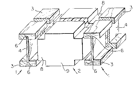
Figure l is an exploded, perspective view Erom one
end of a first embodiment oE a wall assembly in accordance
with the present invention;
Figure 2 is an exploded, perspective view of a
second embodiment of the wall assembly of the present invention;
Figure 3 is an exploded, perspective view of all of
the elements required to form a wall assembly of the type
shown in Fig. l;
Figure 4 is an exploded, per~pective view of all of
the elements required to form a wall assembly of the type shown
in Fig. 2;
Figure 5 is a plan view of one corner of a wall assembly
constructed with the elements of Fig. 3;
Figure 6 is a plan view of one corner of a wall
assembly constructed with the elements of Fig. ~; and
Figure 7 is a side elevation view of a wall assembly
of the type shown in Fig. 5 or 6.
Referring to Fig. 1, the basic elements of a wall
assembly in accordance with the present invention include an
I-beam type or I-shaped post yenerally indicated at 1 and a
rigid foam plastic insulating panel generally indicated at 2.
The post l does not embody a new s-tructure, i.e. posts of this

727
type are known. However, it is helieved -that such posts have
not been employed in the manner proposed herein. ~`ach post 1
is defined by a pair of spaced apart 2" x 6" spruce planks or
boards 3 wh:ich are interconnected by a narrow wooden web 4 oE
plywood. The web 4 ex-tends into rectangular, lonyi-tudinally
extending grooves 6 in the boards 3. The web 4 is glued to
the boards 3.
The boards 3 and web 4 define rectangular recesses
for receiving lateral projections 8 on the insulating panel 2.
The panel 2 is defined by a rigid foam plastic body 9 of cruci-
form cross section. The foam plastic is expanded polystyrene.
By using a cruciform cross section with the lateral projections
8, the body 9 can be used to interconnect adjacent pos-ts 1, the
projections 8 extending into aligned recesses in the posts.
Referring to Fig. 2 a second embodiment of the invention
includes -the posts 1, which have been modified to include
insulating inserts 10, and a rigid foam plastic panel generally
indicated at 12. The inserts 10 are integral with the posts 1
and include rectangular, longitudinally extending grooves 14
in the centre of the outer, side edge thereof for receiving
a rigid foam plastic spline 15 (Figs. 4 and 6). The panel 12
is basically a rectangular parallelepipedic block or body 16
with rectangular, longitudinally extending grooves 17 in the
centre of each side thereof for receiving splines 15. As shown
in Figs. 3 and 4, -the panel 9 or 16 can include a transversely

~ ~7727
e~tending groove 18 Eor carrying electrical wires.
A corner in a wall assembly producecl using the posts 1
and panels 2 of F`ig. 1 requires only one additional element,
namely a rectangular insulating plug 19 (Fig. 3), which is
inserted into an outer groove in the post 1. By the same token,
the posts 1 and panels 12 of Fig. 2 recluire only a plug 18 for
completing a corner structure.
With reference to Fig. 5, a wall assembly constructed
with the elements of Figs. 1 and 3 includes posts 1 and panels
2 which arestrung together to form walls of the desired length.
A plug 19 is inserted into each end of each wall to complete the
wall. In each case, the plug 19 adds insulation and provides a
smooth end. When forming a corner a spline 15, a second end
post 1 and a plug 19 are added to a first wall, and the post
1 of the second perpendicular wall abuts the inner surface of
the outer post 1 and a portion of -the inner post 1 of such
first wall. As shown in Fig. 6, essentially the same elements
are used to form a wall assembly with a corner when employing
the elements of Figs. 2 and 4.
A complete wall (Fig. 7) is produced using a top
plate 20, a bottom plate 21, posts 1 and panels 2. In order
to form a window opening 23, a lintel 25 is inserted between
two posts 1. The lintel 25 is supported by end posts 26.
A short pos-t 28 and short panels 29 are provided beneath the
lintel, and a sill 30 is at-tached to -the tops of the post 28
and -the panels 29.

727
Thus, there has been descrlbed a relatively simple
wall assembly, which i.s formed usin~ a small number of
elements, and whichisstructurally sound.

Dessin représentatif
Une figure unique qui représente un dessin illustrant l'invention.
États administratifs

2024-08-01 : Dans le cadre de la transition vers les Brevets de nouvelle génération (BNG), la base de données sur les brevets canadiens (BDBC) contient désormais un Historique d'événement plus détaillé, qui reproduit le Journal des événements de notre nouvelle solution interne.

Veuillez noter que les événements débutant par « Inactive : » se réfèrent à des événements qui ne sont plus utilisés dans notre nouvelle solution interne.

Pour une meilleure compréhension de l'état de la demande ou brevet qui figure sur cette page, la rubrique Mise en garde , et les descriptions de Brevet , Historique d'événement , Taxes périodiques et Historique des paiements devraient être consultées.

Historique d'événement

Description Date
Inactive : Périmé (brevet sous l'ancienne loi) date de péremption possible la plus tardive 2008-08-20
Inactive : TME en retard traitée 2007-10-31
Lettre envoyée 2007-08-20
Inactive : CIB de MCD 2006-03-11
Inactive : TME en retard traitée 2005-11-10
Lettre envoyée 2005-08-22
Inactive : TME en retard traitée 2003-10-02
Inactive : Lettre officielle 2003-09-17
Lettre envoyée 2003-08-20
Inactive : Lettre officielle 2001-06-20
Exigences pour le changement d'adresse - jugé conforme 2001-06-20
Accordé par délivrance 1991-08-20
Déclaration du statut de petite entité jugée conforme 1987-06-01

Historique d'abandonnement

Il n'y a pas d'historique d'abandonnement

Titulaires au dossier

Les titulaires actuels et antérieures au dossier sont affichés en ordre alphabétique.

Titulaires actuels au dossier
NASCOR INCORPORATED
Titulaires antérieures au dossier
RICHARD DETTBARN
Les propriétaires antérieurs qui ne figurent pas dans la liste des « Propriétaires au dossier » apparaîtront dans d'autres documents au dossier.
Documents

Pour visionner les fichiers sélectionnés, entrer le code reCAPTCHA :


Pour visualiser une image, cliquer sur un lien dans la colonne description du document. Pour télécharger l'image (les images), cliquer l'une ou plusieurs cases à cocher dans la première colonne et ensuite cliquer sur le bouton "Télécharger sélection en format PDF (archive Zip)" ou le bouton "Télécharger sélection (en un fichier PDF fusionné)".

Liste des documents de brevet publiés et non publiés sur la BDBC .

Si vous avez des difficultés à accéder au contenu, veuillez communiquer avec le Centre de services à la clientèle au 1-866-997-1936, ou envoyer un courriel au Centre de service à la clientèle de l'OPIC.


Description du
Document 
Date
(aaaa-mm-jj) 
Nombre de pages   Taille de l'image (Ko) 
Page couverture 1993-10-21 1 10
Revendications 1993-10-21 1 34
Dessins 1993-10-21 2 60
Abrégé 1993-10-21 1 23
Description 1993-10-21 5 130
Dessin représentatif 2002-01-11 1 16
Avis de rappel: Taxes de maintien 1998-05-21 1 119
Avis de rappel: Taxes de maintien 1999-05-25 1 120
Avis de rappel: Taxes de maintien 2000-05-24 1 119
Avis de rappel: Taxes de maintien 2001-05-23 1 119
Avis de rappel: Taxes de maintien 2002-05-22 1 119
Avis de rappel: Taxes de maintien 2003-05-21 1 115
Avis concernant la taxe de maintien 2003-09-17 1 174
Quittance d'un paiement en retard 2003-10-20 1 166
Avis de rappel: Taxes de maintien 2004-05-25 1 117
Avis de rappel: Taxes de maintien 2005-05-24 1 118
Avis concernant la taxe de maintien 2005-10-17 1 173
Quittance d'un paiement en retard 2005-11-17 1 166
Avis de rappel: Taxes de maintien 2006-05-24 1 118
Avis de rappel: Taxes de maintien 2007-05-23 1 120
Avis concernant la taxe de maintien 2007-10-01 1 173
Quittance d'un paiement en retard 2007-11-13 1 164
Correspondance 2003-09-17 1 24
Taxes 2003-09-02 1 58
Taxes 2003-10-02 1 41
Taxes 1999-08-09 2 166
Taxes 2000-06-16 1 25
Taxes 1998-06-19 2 211
Correspondance 2001-06-20 2 38
Taxes 2001-06-26 2 210
Taxes 2002-08-01 2 123
Taxes 1997-06-09 1 38
Taxes 1997-09-23 4 100
Taxes 2004-07-30 1 56
Taxes 2005-11-10 2 59
Taxes 2006-06-28 4 129
Taxes 2007-10-31 4 190
Taxes 1993-06-22 1 30
Taxes 1996-06-11 1 35
Correspondance 1997-01-10 2 33
Correspondance 1996-12-23 1 36
Taxes 1995-08-15 1 40
Taxes 1994-08-16 1 43