Note: Descriptions are shown in the official language in which they were submitted.
1 53,031
ELECTRICAL DISTRIBUTION APPARATU5
HAVING DRAW-OUT SURGE ARRESTER
BACKGROUND OF T~E INVENTION
.
Eield of the Invention:
The invention relates in general to electrical
distribution apparatus, and more specifically to electrical
distribution apparatus having overvoltage or surge
arresters.
Description o the Prior Art:
Electrical distribution apparatus, such as
distributi~n transformers, must be protected from over-
voltages or voltage surges, such as due to li~htning.Pole mounted distribution transformers are inaccessible by
the public, and thus surge arresters are quite naturally
mounted on the outside of the transformer tank.
Pad~mounted distribution transformers used with
underground dlstribution systems have a protective cover
over the terminal or bushing compartment. Thus, with
live-front designs, a urge arrester may be mounted exter-
nal to the terminal wall, but within the protective cover.
With dead-ront designs, a surge arrester has been mounted
in a plug-in elbow, with one arrester elbow for each
primary bushing elbow. With loop feed, the high voltage
connection is from a primary bushing well to an arrester
bushing well, with the connection being made inside the
tank. With radial feed, spacial dual type feed-through
insarts for plug-in elbows are provided in which the high
:
~ :.
-, , , ~ . . : .
.. . ., , , , , ~ ~ .
., . - :,, , . . : . , . . - , : ,
~x~
vol-tage connec-tion from the bushing elbow to the
associated arrester elbow is outside the tank.
Plug-ln elbows and bushing wells are
costly, so surge arresters have also been mounted
inside the transformer tank, directly in the liquid
dielectric, e.g., mineral oil. The oil-immersed type
has the advantage of being pro-tected from the
environmen-t external to the transformer tank, which
environment has been a major cause of arrester
failure over the years. The oil-immersed type,
however, suffers many disadvantages. For example,
the arrester may contaminate the liquid dielec-tric in
the event the arres-ter is destroyed while
accommodating a voltage surge. Also, the in-oil type
is inaccessible, and thus not easily inspected or
replaced. Some tanks are sealed, with no hand-hole
cover, and even with a hand-hole cover, reaching
blindly into the liquid dielectric to locate, remove
and replace an arrester is time consuming and messy.
Certain transformer surge and dielectric tests mus-t
be made without the surge arxester in the circuit.
With the in-oil type of arrester, these tests are
very costly since the arrester must be disconnected
for the test and reconnected afterwards. F'inally, a
surge arrester is not required for every pad-mounted
distribution transformer. For example, an arrester
may be used at the initial line drop from the
overhead to the underground, and at the end of the
line. The end of the line, however, changes with
system expansion. With the in-oil type it is a
practical necessity to purchase all transformers with
arresters.
.~ ,
, . . . . .
- :~ . : .
,
' , ' ' '': ,
..
~ ~37~68
- 2a -
SUMMARY OF THE INVENTION
In accordance wi-th the invention there is
provided an electrlcal distribution apparatus
comprising:
an electrically grounded metallic tank
having an opening,
an electrical element in said tank,
and an arrester assembly including a
housing which extends into said tank via said tank
opening, and a draw-out surge arrester in said
housing having first and second insulatively spaced
electrical contacts,
said housing including first and second .
insulatively spaced metallic means,
said first metallic means of said housing
mechanically mounting said housing to said tank and
electrically connecting the first electrical contact
of said draw-out surge arrester to said grounded
metallic tank,
said second metallic means of said housing
electrically connecting the second electrical contact
of said draw-out surge arrester to said electrical
element.
In accordance with a further embodiment of
the invention there is provided an electrical
distribution transformer comprisingO
an electrically grounded metallic tank
having a wall portion which defines openings,
a liquid dielectric disposed in said tank,
primary and secondary bushings mounted on
the wall portion of said tank each having an
electrical conductor element which extends through a
tank opening,
'
~,
'. ' ' ' ' .. ' ' . ' '
786~
2b -
a core-coil assembly immersed in said
liquid dielectric and having primary and secondary
windings connected to said primary and secondary
bushings, respectively,
a surge arrester housing defining an
elongated opening having at leas-t one open end
adapted to removably receive a draw-out surge
arrester,
said arrester housing being disposed
1~ through an opening in the wall portion of said tank,
and including metallic tank wall mounting means on
said arrester housing which is electrically connected
to said grounded metallic tank and which defines a
first electrical contact, said arrester housing
further including a second electrical contact, and
insulative means which separates said first and
second electrical contacts,
and means electrically connecting the
second electrical contact of said arrester housing to
a primary bushing.
In more detail, the presen-t invention
relates to new and improved electrical distri~ution
apparatus of the type having a grounded metallic
tank, and which requires, or may require, surye
arrester protection. According to the teachings of
the invention, an arrester assembly for such
apparatus includes a housing and a draw-out surge
arrester. The housing is a simple, low-cost
structure having first and second insulatively spaced
metallic members. The first
,~q,
: ~ ' " ' ' ' ," ' , ' ' . : '' ~,, ' ,' -
.
. '' ,~ ' , :
. ' ' . " ': ' '
... . .
.
3 53,031
metallic member is multi-~unction, mechanicall~ mountiny
the arrester housing in a tank wall opening, while defining
a first electrical contact which is automatically electri-
cally connected to the grounded metallic tank. The second
metallic member functions as a second electrical contact,
and as a terminal for an internal tank electrical lead
which is connected to a circuit point to be protected. The
low cost arrester housing is supplied with each unit of the
distribution apparatus, either with the associated draw-out
surge arrester, or with a protective dust cap, as desired.
Thus, for nominal additional cost, every unit of the
distribution apparatus has provisions for overvoltage surge
protaction, which can become functional by simply removing
the protective cap and inserting a draw-out surge arrester
lS into the arrester housing. If the draw-out surge arrester
is assembled with its housing and dielectric tests are
required, the draw-out surge arrester is simply removed
un~il the tests have been completed. The arrester itself
may be easily inspected, and replaced if necessary. A unit
which initially required surge protection, and through
distribution line expansion or change no longer re~uires
such protection, may simply have the draw-out surge arrest-
er removed and placed into another unit which may now
require such protection.
In a preferred embodiment of the invention, the
"w811" created by the housing is "dry", i.e., it is hermet-
ically sealed from the internal tank environment. The
external open end of the housing, however, is not sealed
when the draw-out surge arrester is assembled therewith.
Thus, the small I2R lo.ss of a gapless type surge arrester
will not produce damaging heat build~up, as the heat will
escape from the dry well to the cooler terminal compartment
of the apparatus by natural thermal flow.
While the dry well may extend into a gas space of
the associated distribution apparatus, it is preferred that
the dry well extand into any liquid dielectric which may be
contained in the grounded tank. This will minimize the
~ .
'
4 S3,03L
clearance distance between the arrester and the yrounded
tank.
It is important to recognize that the required
arrester housing length is significantly shorter than would
be required for a draw-out fuse for the same voltage. 30th
fuse term1nals on the fuse sheath must be spaced from the
grounded tank wall by predetermined distances, requiring
substantial penetration o the fuse assembly into the tank.
Thus, a draw-out fuse may re~uire rearrangement of the
internal components, and possibly an increase in tank
dimensions, while the draw-out arrester of the present
invention may be easily accommodated without resorting to
such costly expedients. In the present invention, the
housing length is shorter by at least the dimension between
the two contacts of a fuse housing, for the same withstand
voltage.
While it is preferred that the well created by
the housing is dry, i.e., hermetically sealed from the
internal tank environment, another embodiment of the
invention extends the well into liquid dielectric and
provides openings in th~ housing wall to provide flow of
the liquid dielectric coolant past the draw-out arrester.
The openings are provided with a suitable mesh or non-
conductive screen to prevent contamination of the associat-
ed distribution apparatus in the event the arrester isdestroyed while accommodating a voltage surge. This
embodiment has an advantage of providing liquid cooling for
the arrester, but it does requir~ that the draw-out surge
arrester seal the external housing opening when it is
assembled with the arrester housing.
The draw-out surge arrester portion of the
arrester assembly includes an insulative tubular member
which contains the arrester blocks or non-linear resistors,
with metallic end caps for the tube functloning as first
and second electrical contacts for the non-linear resis-
tors. First and second garter spring contacts are held
against the first and second end caps, respectively, to
,. . : , :
.
,
9,.~
~ 53,031
provide first and second electrical contacts which respec-
tively engage the insulatively spaced first and second
stationary electrical contacts of the arrester housing. By
pressing the garter spring contacts dlrectly against the
metallic end caps, the length of the draw-out assembly may
be controlled by the minimum electrical clearance re~uired
between the contacts of the arrester housing, and not by
the mechanical limitations of the draw-out portion of the
arrester assembly, assuring minimum penetration of the
arrester housing into the tank of the distribution
apparatus.
BRIEF DESCRIPTION OF THE DRAWINGS
The invention may be better understood, and
further advantages and uses thereof more readily apparent,
when considered in view of the ollowing detail description
of exemplary embodiments, taken with the accompanying
drawings in which:
Figure 1 is a perspective view of a pad-mounted
electrical distribution transformer constructed according
to the teachings of the invention;
Eigure 2 is a fragmentary view, partially in
section of the distribution transformer shown in Figure 1,
illustrating a dry-well embodiment of the invention;
Figure 3 is a cross-sectional view of an arrester
housing constructed according to an embodiment of the
invention;
Figure 4 is a fragmantary vlew, partially in
section, o~ a draw-out portion of the arrester assembly,
constructed according to an embodiment of the invention;
Eigure 5 is a cross-sectional view similar to
that of Figure 2, except illustrating the arrester mounted
in the gas space o~ the associated distribution apparatus,
instead of in liquid dielectric;
Figure 6 is a cross-sectional view of an arrester
housing with a protective cap, for an application of the
distribution apparatus which, at least at the moment, does
not require surge voltage protection; and
'
:
3713~
~ 53,031
Figure 7 is a fragmentary view, parti.aLly in
section, of a wet-well embodiment of the invention.
DESCRIPTION OF PREFERRED EMBODIMENTS
The invention relates in general ~o any type of
power frequency electrical distribution apparatus, single
phase or multiple phas~, having a grounded metallic casing
- or tank, which may require overvoltage surge protection.
For example, such apparatus may be a distribution trans-
former, or an electrical switch used in a distribution
system. For purposes of example, the invention will be
described relative to a pad-mounted, single-phase electri-
cal distribution transformer, such as used by electrical
utilities to provide 60 Hz, 120/240 volts for residential
use.
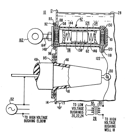
Referring now to the drawings, and to Figures 1
and ~ in particuLar, there is shown a pad-mounted, single-
phase elPctrical distribution transformer 10 constructed
according to the teachings of the invention. Figure 1 is a
perspective view of transformer 10, and Figure 2 i5 a
fragmentary, sectional view of transformer 10. Transformer
10 includes an enclosed metallic tank 12 having a front
wall or surface 14 on which the electrical terminals are
mounted, such as high voltage bushing wells 16 and 18, and
low voltage bushings 20, 22 and 24. Two high voltage
2S bushing wells 16 and 18 are provided for loop faed, while
only one high voltage well would be provided for radial
feed. Tank 12 is electrically grounded, as indicated at 13
in Figure 2. A core coil assembly 26 is disposed within
tank 12, immersed in a suitable liquid dielectric 28, such
as mineraL oil. The invention is also suitable for any
other type of environment, such as the silicones, C2C14,
high molecular weight ~ineral oil, or even gases, such as
air, nitrogen, SF6, and the like. The core-coil assembly
26 includes a primary winding 30 which is connected to the
high voltage bushing wells 16 and 18, and ~ secondary
winding 32 which is connected to the low voltage bushings
20, 22 and 24.
.. . . .
., , , : '
.
7!3~8
7 53,031
A cabinet or compartment 34 is formed adjacent to
the front wall 14 of tank 12, for enclosing the bushings,
the cables which rise from the ground and connect to the
bushings, as well as any other items commonly disposed on
the front wall of the tank 12. Cabinet 34 includes a
U-shaped sill 36 which is attached to the tank 12, and a
terminal cover or hood 38 which is pivotally attached to
the tank 12. Cover 38 has the open position illustrated,
which enables authorized personnel to gain access to the
cable compartment 34, and a closed position. In the closed
position, cover 38 is locked to the sill 36 via a padlock
(not shown) in a sill recess 40.
According to the teachings of the invention, a
surge arrester assembly is provided for each high voltage
bushing well, such as surge arrester assemblies 42 and 44
shown in Figure 1. For radial eed applications, only one
surge arrester assembly would be required. For three-phase
apparatus, three surge arrest~r assemblies would be
provided.
Figure 2 is a fragmentary, sectional view of
arrester assembly 42 which is associated with high voltagé
bushing well 16. An insert 46, and an insulated plug-in
elbow 48 are shown in Figure 2, which completes an electri-
cal circuit from a terminal 50 at the innermost end of high
2S voltage bushiny well 16 to a source 52 of electrical
potential. Terminal S0 is connected to on~ side of the
high volta~e primary winding 30 of the core-coil assembly
26.
Surge arrester assembly 42 includes a housing
portion 54 and a draw-out arrester portion 56. In a
preferred embodiment of the invention, housing 54 forms a
dry well, i.e~, it is hermetically sealed from the internal
transformer environment, and this dry well embodiment is
shown in Figures 2, 3, 5 and 6. A wet-well embodiment, to
be hereinafter described, is shown in Figure 7. Housing
por~ion 54, as shown in cross-section in Figure 3, includes
first and second insulatively spaced metallic end portions
- , , .
.
- . . :, . ' : : ,' ' .
'
68
8 S3,031
58 and 60, respectively. The electrical insulation for
mounting and spacing the metallic end portions 58 and 6Q is
provided by a tubular member 62 selected for its electrical
insulating characteristics, mechanical strength, and its
ability to withstand the chemical environmant and tempera-
tures to which it will be subjected inside the transformer
tank 12. A filament wound glass-filled epoxy has been
found to be excellent for all of the hereinbefore mentioned
transformer insulating and cooling dielectrics, gas or
liquid. Tubular member 62 has first and second axial ends
64 and 66, respectively, and the wall portion 67 of the
tubular member has an inner cylindrical surface 69 which
defines an opening 68 having a longitudinal axis 71 which
extends between its ends. Since this is a dry-well embodi-
ment, wall portion 67 is solid, i.e., devoid of openings.
The first metallic end portion or member 58 of
arrester housing 54 provides many different functions. It
is formed of a good electrical conductor, such as copper,
aluminum, steel or brass, and is essentially a tubular
member having first and second axial ends 70 and 72,
respectively, with a wall portion 73 having a smooth inner
cylindrical surface 74 which defines an opening 76 which
extends between its ends. Wall portion 73 is exte~nally
circumferentially flanged, having a flange 78 disposed
intermediate ends 70 and 72. Flange 78 exten~s perpendicu-
larly outward from outer cylindrical surfaces 80 and 82, to
provide first and second flat surfa~es 84 and 86 which are
perpendicular to the longitudinal central axis 88 of member
58. Flange 78 may have a plurality of openings, such as
opening 90, which extend between surfaces 8~ and 86, for
receiving metallic stud members, such as stud 92 shown in
Eigure 2, which stud members are welded to tank wall 14.
Alternatively, th~ tank mounted stud members 92 may proceed
through openings in a separate ring-type flange member
which overlaps flange 78 and clamps tightly to surface 84
of flange 78. For example, a ring-type flange member may
be used similar to fLange 95 shown holding bushing well 16
.
- . . ..
.
7~6~3
g S3,031
to tank 12. Flange 78 also has a circumferential yroove 94
disposed in flat surface 86 for receiving a seal.ing gasket
96 shown in Figure 2. The second axial end 72 of the first
metallic portion 58 may be suitably grooved for receiving
the first axial end 64 of insulative tubular member 62. A
suitable adhesive, such as an epoxy, may be used to attach
ends 64 and 72, with openin~s 76 and 68 being coaxial.
The first metallic end portion 58 thus provides
the mechanical function of securely fastening arrester
housing 54 within an opening 98 in tank wall 14, while
forming a hermetic seal between the flange 78 and the tank
wall 14 via the gasket 96. The metallic end portion 58
also provides electrical functions, as its inner cylindri~
cal surface 74 defines a first electrical contact for
cooperation with an electrical contact on the draw-out
arrester portion 56. The metallic end portion 58 also
electrically connects the first ~lectrical contact defined
by surface 74 to the grounded metallic tank 12 when nuts
are assembLed with the tank studs, such as nut 93 shown in
Figure 2.
The second metallic end portion 60 functions as
an electrical contact for a second contact on the draw-out
arrester portion 56. It also provides support for a
terminal adapted for connection to the portion of an
electrical circuit within the tank 12 to be protected
against overvoltage surges. Finally, in this dry well
embodiment, it hermetically seals the open end 66 of the
insulative tubular member 62.
More specifically, as illustrated in Figure 3,
the second metallic end portion 60 may be constructed of
first and second metallic members 100 and 102, each having
a good electrical conductivity, such as copper, aluminum,
steel or brass. Member lO0 is cup-shaped, having a cylin-
drical wall portion 104 symmetrical about a longitudinal
axis 105, with the cup-shape defining an open end 106 and a
closed end 108. Member 102 is tubular, having a wall
portion lO9, also symmetrical about axis 105. Member 102
.
- . ,
,,
': ' :,
1~8~ i8
10 53,031
has first and second axial ends 110 and 112, respectively,
with end 112 having a small right angle flange 114 which
extends perpendicularly outward from wall portion 109.
Member 102 is coaxially disposed within the open end 110 of
member 100, with flange 114 contacting member 100 at the
transition point between wall portion 104 and end portion
108. Flange 114 is suitably attached to member 100, such
as by brazing. Flange 114 is sized, as is the outside
diameter of wall 109 of member 102, to provide a snug
recess or space between walls 109 and 104 for receiving end
66 of insulative tubul~r member 62. End 66 may be secured
in this recess by a suitable adhesive. Wall 109 defines a
cylindrical inner metallic surface 116 which functions as a
second electrical contact of arr~stsr housing 54.
; 15 A clamp 118, formed of tin-plated steel, for
example, is slipped about the outer surface of wall portion
104, and firmly clamped in this position by a suitable nut
and bolt combination 120 shown in Figure 2. The nut and
bolt combination 120 secures one end of an electricai lead
122 shown in Figure 2, the other end of which is connected
to the circllit point to be protected, such as to terminal
50 of bushing well 16 which thus protects primary winding
30 from voltage surges which may attempt to enter the
associated end of the winding.
The draw-out surge arrester portion 56 of surge
arrester assembly 42, best shown in Figures 2 and 4,
includes an insulative tubular member 124 which may be
similar in construction to tubular member 62. Tubular
member 124 has a solid wall portion 126, i.e., it is devoid
of openings through the wall portion, first and second
axial ends 128 and 130, respectively, and an inner cylin-
drical surface 132 which is symmetrical about a longitudi-
nal axis 134. Inner surface 132 defines an opening 136
which extends between ends 128 and 130. The draw-out surge
arrester 56 is preferably of the gapless type, having the
requisite number of non-linear resistive elements or blocks
138, such as zinc-oxide, with the number of elements
,~ , ' , ' .
' , ' ' , ' '
~ ~78~8
11 53,031
depending upon the normal voltaye level of the circuit
point to be protected. For example, if each arrester
element is rated 3 KV, and the circuit point to be protect-
ed normally operates between 6 KV and 9 KV, three elements
S would be provided. The non-linear resistive elements are
stacked in series and the ends of the stack are el~ctrical-
ly connected to electrically conductive first and second
end cap members 140 and 142. respectively, which me~ers
seal the open ends 128 and 130, respectively, o~ the
tubular member 124. End cap members 140 and 142 are
constructed of a good electrical conductor, such as copper
or brass. The ends of the stack of non-linear resistor
elements 138 are connected to the end cap members 140 and
142, such as via one or more compression springs, such as
compression springs 144 and 146.
While the preferred embodiment of the invention
utilizes a gapless surge arrester, the teachings of the
invention may also apply to the use of a gap-type surge
arrester, such as a gap-type arrester having non-linear
resistive elements constructed of zinc-oxide, or silicon
carbide. The gapped t~pe arrester has an advantage in that
there are no I2R losses until the arrester operates, and
thus there is no heat to remove during normal monitoring.
~ This advantage over the gapless arrester is offset, howev-
er, by the fact that the gapped arrester is longer and morecostly than the gapless type, and the gap must be protected
from contamination, necessitating a dry well design.
In a preferred embodiment of the invention, first
and second garter spring contacts 148 and 150, shown in
Figure 2, are in direct contact with the first and second
metallic end caps 140 and 142, respectively, which minimiz-
es the overall length of the surge arrester. By minimizing
the length, the draw-out surge arrester 56 may be designed
according to the minimum length required between the spaced
contacts of the arrester housing 54, as required for
electrical clearance. If the draw--out arrester 56 exceeds
this minimum electrical clearance dimension, then the
- '' '. ' ' : .:
'-
~.2~
12 53,031
contacts of the housing 54 will have to be spaced in excessof the minimum electrical clearance, increa~ing the pene-
tration of the housing into tank 12. This preferred
construction, along with the arrester housing construction
in which the mounting assembly functions as an electrical
contact which directly connects one end o~ the draw-out
arrester 56 to the grounded metallic tank 12, enables a
very short housing 54 to be utilized. For example, a
draw-out fuse for a 7200 volt application would extend into
10 tank 12 about 20 inches, while arrester housing 54 would
extend into tank 12 by only about 8.5 i~ches for the same
7200 volt application. The function of placing the garter
springs 148 and 150 directly against metallic end cap
members 140 and 142 may be accomplished as shown in Figure
15 4, by constructing end cap members 140 and 142 in the form
of a metallic spool in which the end caps 140 and 142 form
one flan~e of the spool. Thus, gartar springs 148 and 150
may encircle axially extending cylindrically shaped por-
tions 152 and 154, respectively, which are integral with
20 the end caps 140 and 142, or suitably attached thereto.
The extreme outer ends of projections 152 and 154 terminate
in flanges 156 and 158, respectively. Flanges 156 and 158
may be integral with projections 152 and 154, respectively,
or suitably attached thereto, as desired.
Flange 156 and cylindrical projection 152 define
a tappad opening 160 coaxial with the longitudinal axis or
centerline 134. To simplify part manufacture, flange 158
and cylindrical projection 154 may also have a tapped
opening 160'. Tapped opening 160 receives a handle or hook
30 eye 162. Handle 162 has a threaded shaft 164 which re-
ceives a ~amb nut 166 and a dust cover 168 before the shaft
is threadably engaged with tapped opening 160. It is
important to note that the dust cover 168 does not seal the
open external end of housing 54 when the draw-out surge
arrester 56 is inserted into housing 54. A space is
intentionally provided at the external end o the arrester
housing 54 so heat produced by the small I2R loss in the
. - ' '
.
.
7~
13 S3,031
~on-linear resistive elements 138 may flow throuyh the
relatively open garter spring contact 148 and out of the
dry well defined by the arrester housing 54. It will also
be noted that when the draw-out surge arrester 56 is
inserted into housing 54 that the garter springs 148 and
150 are compressed to make good electrical contact with the
inner cylindrical surfaces 74 and 116 which define the
electrical contacts of the arrester housing 54. This
automatically connects garter spring 148 to the grounded
tank 12, and it also automatically grounds handle 162.
Figure 2 illustrates the preerred embodiment of
the invention in which the housing 54 is immersed in the
liquid dielectric 28. This is a preferred embodiment
because it enables the spacing between the arrester housing
and the grounded tank to be reduced, compared with the
spacing which would be re~uired in air, for any given
withstand voltage. The teachings of the invention may also
be practiced by inserting housing 54 into gas, such as into
the gas space 170 located above the liquid dielectric 28,
with this embodiment of the invention being illustrated in
Figure 5. The gas in the gas space 170 may be air, it may
be an inert gas, such as nitrogen, or it may be a gas
having a superior electrical breakdown strength, such as
SF6 .
It will be noted that the relatively more costly
portion of the arrester assembly 42 is the draw out portion
56 which contains the non-linear resistive elements 138.
Since the housing portion 54 has a relatively simple
structure and low manufacturing cost, it ls economically
attractive to manufacture all units of the distribution
apparatus which may require surge protection at some point
in the future with an arrester housing 54 for each circuit
point which may require protection. This embodiment of the
invention is shown in Figure 5, with a suitable protective
cap or cover 172 being used to cover the open end of
arrester housing 54 until such time that surge protection
is required. Units which are shipped with the draw~out
', , .
-' `
~4 ~3,~31
surge arrester, if subsequently used where surye protection
is not required, may have the draw-out portion 56 removed
and used with another unit, with a cap or cover 172 being
used to cover the opening in the arrester housing 54.
While the dry-well concept described to this
point is the preferred embodiment, because it is the
simplest and lowest cost while providing the minimum
penetration o the arrester housing into the tank, the
teachings of the invention are also applicable to a wet-
well design. In a wet-well design both the arrester
housing and the surge arrester portion of the draw-out
assembly are immersed in the liguid dielectric 28. This
embodiment of the invention is shown in Figure 7 relative
to a surge arrester assembly 42'. Components which do not
need to be modified in the Figure 7 embodiment are given
the same reference numerals as in the dry-well embodiment,
and will not be described again. Similar but modified
components are given the same reference numerals as their
counterparts in the dry-well embodimant, with the addition
of a prime mark.
More specifically, an opening 98' is required in
wall 14 of tank 12 which is located slightly above the
level of the liquid dielectric 28, to prevent the liquid
dielectric 28 from flowing out of the tank 12 when the
draw-out arrester portion 56' is removed from the arrester
housing 54'. The arr0ster housing portion 54' is modified
by changi~g the angle of the mounting flange 78', which is
associated with the first metallic end portion 58', rela
tive to the longitudinal axis 88' of end portion 58'. This
angle is selected to minimize the length of the arrester
housing. A ~uitable angle, for example, indicated at 180,
is about 35. The first metallic end portion 58' of
housing 54' i5 longer than its counterpart in the dry well
embodiment, in order to electrically connect garter spring
35 148 to the electrically grounded tank 12. A plurality of
op~nings are provided in wall 67' of insulative tubular
member 62', such as openings 182 and 184, to enable the
,
7~
liquid dielectric 28 to flow into arrester housing
54' and surround the active portion of -the draw-out
surge arrester 56'. As illustrated in ~igure 7,
openings 182 and 184 may be covered with mesh 186 and
188, respec-tively, which has openings for enabliny
flow of the liquid dielectric 28 while preventing
particles of the draw-out surge arrester 56' from
leaving the wet well, should the arrester fail while
accommodating an overvoltage surge.
The draw-out portion 56' of arrester
assembly 42' is modified by providing a shaft 164'
which is longer than the shaft 164 of the dry well
embodiment, and by providing a handle 162' which
seals the open end of housing 54' after the draw-out
surge arrester portion 56' has been inserted into the
arrester housing 54'. As illustrated in Figure 7, an
elastomeric, resilient stopper 190 may be expanded
after insertion into the open end of housing 54', by
an externally actuatable cam 192 which actuates a rod
194 connected to the stopper 190, similar to a
thermos bottle top.
In summary, -there has been disclosed new
and improved electrical distribution appara-tus, such
as a pad-mounted distribution transformer, which has
surge voltage protection withou-t resorting to costly
insulated plug-in elbows, and without requiring surge
arresters to be inaccessibly mounted within the tank
of the apparatus to be protected. The surge arrester
of the present invention requires little penetration
depth into the apparatus tank, due to the unique
multifunction construction of the arrester housing
and draw-out assembly, and it has the a~vantages of
enabling the active elements of the arrester to be
easily removed, inspected, and replaced if necessary.
The draw-out arrester may be easily removed for
~,
. .
, -' - ' ~ . . , : - ~:
: . - . - , . ~ . . .
7~
- 16 -
dielectric tests on the associated distribution
apparatus, and just as easily replaced after the
; tests have been completed. The distribution
apparatus may be sold with only the housing portion
of the arrester assembly, if desired, with surge
protection being provided, as required in the future,
by inserting a draw-out surge axrester portion into
the arrester housing.
~ .
~,,
~ ~ .
.
~: , .
''. ~ .' ' ~' '.
' ~ ' ' . :
: : .