Note: Descriptions are shown in the official language in which they were submitted.
CUTTING ELEMENT WITH WEAR RESISTANT CROWN
Technical Field
The present invention relates to cutting elements
5 or inserts for use in rotary drill bits adapted to bore
holes in rock, and to methods for forming such cutting
elements.
Background Art
Cu~ting elements or inserts for use in rotary
drill bits adap~ed to bore holes in rock are conventionally
made entirely of a sintered mixture of tungsten carbide with
about 15 to 17 percent cobalt. Such cutting elements are
tough and fracture resistant (since fracturing of the
15 cutting elements during the drilling process can not be
tolerated) but are not as wear resistant as is desired. It
is known that a sintered mixture of tungsten carbide and
about 9 to 11 percent cobalt has significantly greater wear
resistance than that containing cobalt in the 15 to 17
20 percent range, however, such wear resistant tungsten carbide
; is too prone to fracture to be used to form the entire
cutting element. Thus, as is described in U.S. Patent No.
4,359,335, attempts have~been made to attach wear pads of
such wear resistant tungsten carbide on bodies of such tough
25 tungsten carbide to provide the advantage of both in one
cutting element. As described in U.S. Patent No. 4,359,335,
this has been done by first forming the wear pad by pressing
a mixture of tungsten carbide with about 9 to 11 percent
cobalt in a first die cavity at pressures of about fifteen
30 tons per square inch, positioning that pressed, unsintered
wear pad in a second die cavity, positioning a second
mixture of tungsten carbide and about 15 to 16 percent
cobalt in the second die over the pad, pressing the second
mixture into the die at a pressure of about 15 tons per
35 inch, and then sintering the combination to form the cutting
element or in~ert.
,i:
--2--
Our experience with this method, however, has been
that while it may adequately bond small wear pads on
surfaces of tip portions of cutting elements that project
from sockets in a rotary drill bit in which base portions of
5 the cutting elements are received, the portions of the
tougher tungsten carbide material around the pads will
contact rock being cut or crushed and will wear away rapidly
when compared to the wear pads so that support for the wear
pads is lost and they break away.
When we have attempted to form tip portions for
cutting elements that are completely or almost completely
covered or crowned by the wear resistant tungsten carbide
material using the method described in U.S. Patent No.
4,359,335, voids have been formed at the interface between
15 the wear resistant crown and the underlying base portion of
the tough tungsten carbide material during the sintering
process, and the crown has had a strong tendency to crack
off during use so that the cutting element is unacceptable.
'
20 Brie~ Description
' The present invention provides a method for making
a cutting element with a body of tough tungsten carbide
material and a crown of wear resistant tungsten carbide
material, which cutting element has both more wear
25 resistance at its end portion and toughness than a cutting
element made only of the tough tungsten carbide material.
According to the present invention there is
provided a method for forming a cutting element having a
base portion adapted to be inserted in a socket in a rotary
30 drill bit and a tip portion adapted to project from the
; socket. The method comprises the steps of 1) mixing a crown
mixture of tungsten carbide powder and cobalt powder with
the cobalt powder being in the range of four to eleven
percent (preferably nine to eleven percent) of the crown
35 mixture; 2) mixing a core mixture of tungsten carbide powder
and cobalt powder with the cobalt powder being in the range
of about twelve to seventeen percent lpreferably fifteen to
.
~l~8~34~;
-3-
seventeen perc0nt~ of the core mixture; 3) providing a die
having a cavity approximately the shape of the cutting
element to be formed; 4) positioning in the cavity a
quantity of the crown mixture in the shape of a c.own
5 defining at least the majority of the outer surface for the
tip portion of the cutting element using a pressure of less
than about 600 poun~s per square inc~; 5) positioning in the
cavity a quantity of the core mixture sufficient to form
almost all of the base portion and at least an inner part o
10 the tip portion of the cutting element; 6) pressing the two
quantities of the crown and core mixtures together and into
the die at pressures in the range of about ten to fifteen
tons per square inch; and 7) sintering the pressed insert
te.g., for about sixty minutes at about fourteen hundred
15 degrees Centigrade) to form the cutting element.
The interfaces between the inner parts of the tips
and the crowns of cutting elements made by this method have
been ~ound to be free of voids and are visually irregular
when viewed at a magnification of about 65 times, which
20 irregularity apparently helps provide the strong attachment
bet~een the inner parts and the crowns evidenced by cutting
elements according to the present invention.
Also, the tungsten carbide powder in the crown
mixture preferably has a grain size of under about six
25 microns ~preferably about one to one and one-half microns)
which adds to the wear resistance o the crown, and the
tungsten carbide powder in the core mixture preferably has a
grain size in the range of five to ten microns which adds to
the toughness of the base portion and the inner part of the
30 tip.
Preferably the crown has a maximum thickness
measured axially of the base porti~n and tip portion that is
about fifty percent of the axial height of tip portion so
that only the material forming the crown will engage rock
35 being cut or crushed until the tip portion is suf~iciently
worn away that the cutting element is unserviceable.
~8~
--4--
Brief Description of the Drawing
The present invention will be further described
with reference to the accompanying drawing wherein like
numbers refer ~o like parts in the several views, and
5 wherein:
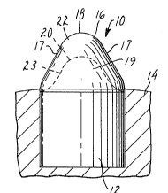
Figure 1 is a vertical side view of a cu~ting
element according to the present invention shown mounted in
a fragment of a rotary drill bit,
Figure 2 is a vertical front view of the cutting
10 element shown in Figure l;
Figure 3 is a drawing of an interface between an
inner part of a tip and a crown of the cutting element of
Figure 1 magnified about sixty-five times; and
Figures 4 through 6, which have parts sectioned to
lS show details, sequentially illustrate method s~eps used in
making the cutting element shown in Figures 1, 2 and 3.
Detailed Description
Referring now to Figures 1 and 2 there is shown a
20 cutting element according to the present invention generally
designated by the reference numeral 10.
The cutting element 10 includes a cylindrical base
portion 12 adapted to be inserted in a socket in a rotary
drill bit 14, and a tip portion 16 adapted to project from
25 the socket, which tip portion 16 has a generally conical end
surface portion 19 disposed at about a 35 degree angle with
respect to the axis of the cutting element 10, planar front
and rear surface portions 17 forming an included angle of
about 70 degrees, and an arcuate distal end surface portion
30 18 (e.g., 0.06 inch radius) joining the front end rear
surface portions 17. The cutting element 10 comprises a
tough core material formed from a sintered core mixture of
tungsten carbide powder having a grain size in the range of
about five to ten microns (preferably about six microns) and
35 cobalt powder providing in the range of about twelve to
seventeen percent (preferably about fifteen to seventeen
percent) of the core mixture by weight, which core material
,
,'
12~ 6
forms the majority of the base portion 12 and an inner part
20 of the tip portion 16; and a wear resistant crown
material formed from a sintered crown mixture of tungsten
carbide powder having a grain size of under about six
5 microns (preferably about one and one-half microns) and
cobalt powder providing in the range of about four to eleven
: percent (preferably nine to eleven perce~nt) of the crown
mixture by weight, which crown material forms a crown 22
covering the inner part 20 and defining the outer or cutting
10 surface of the tip portion 16, and extends slightly along
the upper end of the base portion 16 so that the crown 22
extends slightly into the socket in the drill bit 14 leaving
only the crown 22 exposed for rock cutting or crushing
: action. The interface 23 between the core material and the
15 crown material, as is shown in Figure 3, is free of voids
and is visually irregular along its length when cross
sectioned and viewed at a magnification of about sixty-five
times which helps retain the crown material on the core
material.
Several of the steps in a novel method for forming
the cutting element 1~ shown in Figures 1 through 3 are
shown schematically in Figures 4 through 6.
After mixing the crown mixture 24 of tungsten
carbide powder having a grain size of under about six
.. 25 microns and cobalt powder in the range of about four to
eleven percent of the crown mixture 24, and mixing a core
mixture 26 of tungsten carbide powder having a grain size in
the range of about five to ten microns and cobalt powder in
the range of about twelve to seventeen percent of the core
30 mixture 26; that method comprises the further steps of
providing a die 28 (Figure 4) having a cavity 30
. approximately the shape of (but slightly larger than due to
shrinkage during sintering) the cutting element 10 to be
- formed; positioning in the ~avity 3Q a quantity of the crown
35 mixture 24 in the shape of the crown 22 defining the outer
: surface for the tip por~ion 16 of the cutting element 10 by
inserting a punch 32 (Figure 5) with an appropriately shaped
: tip and applying a force to the punch 32 that applies a
--6--
pressure of less than about 600 pounds per square inch to
the crown mixture 24 to retain it in the shape of the crown
after the punch 32 is removed; positioning in the cavity 30
a quantity of the core mixture 26 (Figure 6) sufficient to
5 form almost all of the base portion 12 and the inner part 20
of the tip portion 16 of the cutting element 10; pressing
the two quantities of the crown and core mixtures 24 and 26
- together and into the die 28 at pressures in the range of
about ten to fifteen tons per square inch as by a ram 34;
10 removing the pressed composite of the crown and core
mixtures 24 and 26 from the die 28; and sintering the
pressed composite ~e.g~, for about sixty minutes at about
fourteen hundred degrees Centigrade) to form the cutting
element 10.
Example
As an illustrative, nonlimiting example, a
plurality of the cutting elements 10 were each formed by
inserting in the cavity 30 of the die 28 the crown mixture
20 24 comprising 89 percent by weight of 1.6 micron tungsten
carbide, 1 percent tantalum carbide which helps inhibit
tungsten carbide grain growth and 10 percent cobalt held in
a pelletized state by a p~araffin wax binder (e.g., the
paraffin wax being about 1 percent of the crown mixture 24
25 by weight but not being considered part of the crown mixture
24 for determining the percentages of the other components).
This crown mixture 24 was shaped by the punch 32 to a layer
along the end portion of the die 28 less than about 0.250
inch thick maximum using about 250 pounds force which was
30 calculated to provide about S00 pounds per square inch to
form the crown mixture 24. The mold was then filled with the
core mixture 26 which comprised 84 percent by weight of 6.4
micron tungsten carbide mixed with 16 percent by weight of
cobalt, which core mixture 26 was also held in a pelletized
35 form by a paraffin wax binder. Both mixtures 24 and 26 were
then pressed into the die 28 by the ram 34 with a pressure
of twelve (12) tons per square inch at room temperature. The
~XB8'11;~
--7--
pressed composite was then removed from the die 28 and
sintered at about 1425 degrees Centigrade for about 1 hour.
Cutting elements lO thus made were tested for
crushing strength by applying forces axially of the cutting
5 elements, and found to withstand about 18,000 pounds load,
which compared favorably to conventional cutting elements of
the same shape made only from the core mixture 26 which
could withstand only about 12,000 pounds loading in the same
test. Comparative wear tests conducted on a single row rock
lO cutting tester showed that the cutting elements 10 according
to the present invention were worn down by about 0.027
inches compared to wear of 0.065 inches on the
aforementioned conventional cutting elements made only from
the core mixture 26. Also the cutting elements lO according
15 to the present invention together with the aforementioned
conventional cutting elements made only from the core
mixture 26 were inserted into a rock drill and used to drill
a bo~e more than 3500 feet deep. The conventional cutting
elements wore to an indistinct conical shape, whereas the
20 cutting elements lO according to the present invention
generally retained their origlnal tooth profile.
The cutting element according to the present
invention and the novel method by which it is made have now
been described with reference to single embodiments thereof.
25 It will be apparent to those skilled in the art that many
changes can be made in the embodiments described without
departing from the scope of the present invention. For
example, the crown of the cutting element may not cover its
entire tip portion, but may end somewhat above the ju-ncture
30 between the tip portion and the base portion of the cutting
element. Thus the scope of the present invention should not
be limited to the structure and method specifically
described in this application, but only by methods and
structures described by the language of the claims and the
35 equivalents of those methods and structures.