Note: Descriptions are shown in the official language in which they were submitted.
31 2~385~)7
HIGH EFFICIFNCY CODI]NG APPARATUS
BACKGROUND ~F THE INVENTION
1. Fi~ld of the Invention
The invention relates to a high efficiency coding apparatus
applied to a picture signal and, more particularly, to a high
efficiency coding apparatus applicable to the case where the
transmission rate of recorded data is controlled to become a
predetermined value corresponding to a transmission path when a
digital video signal is recorded on a magnetic tape.
2. Description of Prior Art
The present application has proposed a high efficiency coding
apparatus for obtaining a dynamic range equal to the difference
between a maximum value and a minimum value of plural picture
elements contained in a two-dimensional block and for performing
the coding adaptive to the dynamic range. Further, a high
efficiency coding apparatus for the coding adaptive to a dynamic
range with respect to a three-dimensional block formed of picture
elements of areas respectively contained in plural frames.
Moreover, a
, "
-- 1 --
. ~ ,
,`: .:: ' ' ~ :
~ X885~
variable-length coding method for varying the bit number depending
on a dynamic range so as to keep constant the maximum distortion
occurring at the time of quantization has been proposed.
The above-mentioned high efficiency coding adaptive to
the dynamic range (called "ADRC") enables great compression of data
amount to be transmitted and is therefore suited to the application
to a digital VTR. Particularly, the variable-length ADRC can
enhance the compression rate. However, since in the variable-
length ADRC, the data amount to be transmitted varies depending on
the contents of pictures, buffering processing is necessary when a
transmission path with a fixed rate such as a digital VTR for
recording a predetermined data amount as one track is employed.
For a buffering system of the variable-length ADRC, the
present applicant has proposed the one in which distribution of
cumulative-type dynamic ranges is formed, a set of threshold values
prepared in advance are applied to the distribution, the amount of
data generated in a predetermined period, for instance, in one
frame period is obtained, and the generated data amount is
controlled so as not to exceed a target value.
Fig. lO shows a graph of cumulative-type distribution
- 2 -
`~
... . - . ~ .
.- ,, . . .. , ~, . . :
- . , . ., . :
~ ~, . . . .
1~3850~
shown in the above-mentioned application. An abscissa of
Fig. 10 is a dynamic range, and an ordinate is a number of
occurrence. Tl to T4 depicted in the abscissa are threshold
values. The bit number of quantization is determined by the
threshold values Tl to T4. In the case of the dynamic range
DR within the range of (a maximum value to Tl), the bit
number of quantization is made to 4; in the case of the
range of (Tl - 1 to T2), the bit number of the ~uantization
is made to 3; in the case of the range of (T2 - 1 to T3), the
bit number of quantization is made to 2; in the case of the
range of (T3 - 1 to T4), the bit number of quantization is
made to l; and in the case of the range of (T4 - 1 to a
minimum ~alue), the bit number of quantization is made to
zero (no code signal is transmitted).
With respect to the cumulative-type distribution r the
occurrence numbers ranging from the threshold value (Tl - 1)
to the threshold value T2 are accumulated with regard to
the occurrence numbers of dynamic ranges from the maximum
value to the threshold value Tl in order to obtain distribu-
tion of the dynamic range DR in a frame period. The occurrence
numbers from the threshold value (T2 - 1) to the threshold
~value T3 are accumulated similarly. Similar
processing is repeated thereafter. As a result, the
occurrence number y at which the dynamic range DR is the
minimum value is equal to the total number (MxN) of the
blocks contained in one frame.
~ ';' , ~ ' ' -', : '
:, .'
8~i07
In this manner, when cumulative type distribution is
formed, the cumulative number up to the threshold value Tl
becomes xl, the cumula~ive number up to the threshold va]ue
T2 becomes (xl + x2), the cumulative number up to the
threshola value T3 becomes (xl + x2 + X3), and th~ cumulative
number up to the threshold value T4 becomes (xl ~ x2 + X3 +
X4). As a result, the amount of` generated information
(total bit number) for a period of one frame is shown by
the following equation:
1 [( 1 x2) xl~ + 2[(xl + x2 -~ x3) - (x
x )] + l[(x1 -~ x2 + x3 + x4) - (xl + x2 3)] 1 2
3 4
The threshold values Tl to T4 are selected so that
the above-mentioned amount of generated information does
not exceed a target value. WXen an optimum value is
obtained with the alteration of the threshold values,
said values xl to X4 are changed depending on the threshold
values, and the calculation of the generated information
amount is made for every set of each threshold value.
Therefore, once a cumulative-type distribution table is
formed, the calculation of generated information can be
made easily.
A system for converging the rate of transmission data
into a target value by changing the four threshold values
in the level direction~ for instance, as mentioned above,
is not sufficient in performance such as the reduction of
.
- . - .
- . .
.' ' . , ~, .
85C)7
distortion of quantization noises, etc.
An object of the invention is, therefore, to provide
a high efficiency coding apparatus capable of achieving
buffering processing of transmission data while suppressing
the deterioration of the quality of reproduced pictures by
changing threshold values for frame-dropping processing in
the time direction as well as by changing threshold values ~:
in the level direction. .
SUMM~RY OF THE INVENTION :~
According to one aspect of the present invention, there
is provided a high efficiency encoding apparatus which
comprises: a circuit for obtaining a maximum value of plural
picture element data included in a block which is composed
of areas belonging to plural continuous fields of a digital
picture signal, a minimum value of said plural picture
element data and a first dynamic range for every said block;
a circuit for averaging corresponding picture element data
between plural fields among plural picture element data of
every block; a circuit for obtaining a maximum value, a
minimum value and a second dynamic value of plural picture
element data of an averaged block; a circuit for detecting
a movement amount of the block on the basis of plural
picture elements in each block; a circuit for giving to an
area with less movement and an area with greater movement
a first number with respect to the first dynamic range
.. ~ ..
.
.. . . ~ . . .
:: , - . .
. .
, .
: . . ~ ' ' . ' ' . . .
:- , .
38~07
and a second number smaller than the first number with
respect to the second dynamic range, respectively, by the
use of a movement amount of the block detected as a border
line by the detection circuit, accumulating said first and
second numbers in a predetermined period and obtaining
distribution; circuits for averaging corresponding picture
element data between plural fields with respect to a block
having less movement than a predetermined amount and
performing frame-dropping processing; circuits for performing
compression-coding the plural picure element data in said
block depending on the first or second dynamic range of the
block; and circuits and for selecting said predetermined
movement amount and a coding bit number depending on
distribution and a transmission capacity of a transmission
path.
In a high efficiency coding apparatus of the present
invention for performing the control so that the amount of
generated information does not exceed a transmission
capacity of a transmission path when ~he high efficiency
coding is executed, a picture is divided into a number of
three-dimensional blocks. The maximum values and minimum
values of picture element data contained in each block and
dynamic ranges are provided. Also, a movement amount (for
; instance, a maximum frame difference ~F) is detected from
picture element data different in time from one another
and included in the same block. In a still block having a
-- 6 --
.~
: ' ' ': . , .' ' :
~ . , .
. .
. - ~ . . .. . . .
- . . . . - -: ... . .
12~3~35V7
little amount of this movement, the amount of generated
information is reduced by frame-dropping processing.
In the frame-dropping processing, a dynamic range
DR2, which is the result of the averaging operation, is
lowered as compared with a dynamic range DR3 for which no
averaging operation is done. For this reason, the position
of a still block at an occurrence number block table becomes
the dynamic range DR2 lower in level than the original
dynamic range DR3. This means a reduction of the amount
of generated information. As a result, to obtain the amount
of generated information, distribution tables on the two
dynamic ranges DR3 and DR2 must be prepared. In the case of
a block with the dynamic range DR2, the:oceurrencebnumber of
(+1), for example, is given for a value equal to or more
than (QF ~ 1) with respect to a maximum frame difference
~F as a movement amount. In the case of the dynamic range
DR3, the occurrence number of (+2), for example, is given
for the range of (O to F) with respect to the maximum
difference QF. In other words, the occurrence number of
(+2) is allotted for the range where a block is handled as
a moving one at the time of decision, while the occurrence
number of (+l) is allotted for the range where a block is
handled as a still one. The distribution tables are
converted into cumulative-type distribution tables for
every amount of a movement.
By the use of the cumulative-type distribution tables,
-- 7 ~
.
, ' ' ' . ' - ~ ' ,':
.~ , ', . , , .", ~
.
'
",' ' ' . ~ ' ' ,. ,: " ' '
: . , ' ' ' : ', . , ' '
8~3507
threshold values and movement threshold values in the level
direction are determined so that the amount of generated
information does not exceed a target value. Decision on
whether the frame-dropping processing is miade is done by
the movement threshold values. Also, variable-length coding,
for example, the word length in the ADRC is controlled by
the threshold values in the level direction. Coded data
obtained by the variable-length ADRC is recorded onto a
magnetic tape.
Since a movement threshold value for giving a reference
of decision on whether the processing of frame dropping
should be performed is changed in this invention, excellent
buffering which cannot be achieved only with the change in
the level direction, can be performed.
Also, in the case where the amount of generated informa-
tion is obtained, the difference in dynamic range between a
still block subjected to frame dropping and a moving block
is taken into account. As a result, the amount of generated
information can be obtained with high accuracy.
BRIEF DESCRIPTION OF THE DRAWINGS
The invention will be more apparent from the following
detailed description when taken in conjunction with the
accompanying drawings, in which:
Fig. 1 is a block diagram showing a structure on the
recording side of one embodiment of the inveneion;
- 8 -
.
- , - : ~ -
:. . ,:, ~ ,
. . . :
.
~-
.
-, ~
~1 2~38507
Figs. 2, 3 and 4 are schematic diagrams for describing
a block construction;
Fig. 5 is a block diagram of one example of an ADRC
encoder;
Figs. 6 and 7 are schematic diagrams for describing
schematic diagrams for describing distribution tables;
Fig. 8 is a block diagram of an example of a three-
dimensional distribution generator and a threshold-value
determination circuit;
Fig. 9 is a block diagram of one example of an address
controller of Fig. 8; and
Fig. 10 is a schematic diagram for explaining a
buffering circuit proposed before.
In the entire drawings, the same reference numerals
denote the same structural elements.
DESCRIPTION OF THE PREFERRED EMBODIMENT
An embodiment of the invention will be described
hereunder referring to the drawings. Description will be
given in the order mentioned below.
a. Structure on the recording side
b. ADRC encoder
c. Forming a three-dimensional distribution table
d. Three-dimensional distribution generator and threshold-
value determination circuil.
~ . . - , .
~ Z8~07
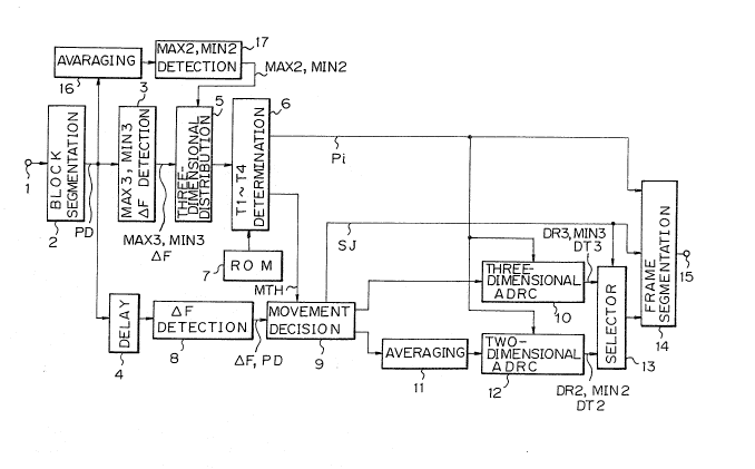
a. Structure on the recording side.
Fig. 1 shows a structure on the recording side of one
embodiment of the invention. In Fig. 1, a digital video
signal in which one sample is quantized with eight bits,
for instance, is supplied to an input terminal indicated
at 1. The digital video signal is given to a block segmenta-
tion circuit 2. Data in the orcler of television scanning is
converted into data in the order of blocks.
At the block segmentation circuit 2, a picture of one
frame of (520 lines x 720 picture elements), for example,
is segmented into (MxN) blocks as shown in Fig. 2. One
block is selected to have the two-frame size. Each frame
is composed of (4 lines x 4 picture elements) as:shown in
Fig. 3, for instance. Moreover, as shown in Fig. 4, a sub-
sampling pattern is made to have an offset between frames
by sub-sampling. In Fig. 4, O indicates a picture element
to be transmitted, and ~ indicates a picture element which
is not transmitted. Such sub-sampling pattern enables good
interpolation in still areas in the case where the inter-
polation is carried out for thinned picture elements. The
digital video signal converted into in the order o~ blocks
ll' B12' B13 --- BMN is generated from the block segmenta-
tion circuit 2.
The output signal of the block segmentation circuit 2
is supplied to a detection circuit 3, a delay circuit 4,
and an average circuit 16. The average circuit 16 adds
data of picture elements at the same position in two areas
-- 10 --
.
:
: ' ~, ; , : ' :
3507
included in one block and divides a result of the addition
by two to convert an original three-dimensional block into
a two-dimensional block. The output signal of the average
circuit 16 is given to a detection circuit 17.
The detection circuit 3 detects not only a maximum
value MAX3 and a minimum value MIN3 of each block but also
a maximum frame difference. The detection circuit 17
detects the maximum value MAX2 and the minimum value MIN2
of the averaged block. As mentioned befoxe, since a block
is composed of areas, which belong to two frames, a maximum
frame difference ~F of the two areas is detected. The
maximum frame difference QF is the maximum value among'
differences obtained by calculating each difference in data
of picture elements at the same position between two areas
constituting one block.
The maximum value MAX3, the minimum value MIN3 and
the maximum frame difference ~F from the detection circuit
3 and the MAX2 and MIN2 from the detection circuit 17 are
given to a three-dimensional distribution generator 5.
The generator 5 calculates the occurrence numbers of
dynamic ranges D DR2 and DR3 using the maximum frame
difference ~F as a paramter and converts the occurrence
numbers of the dynamic ranges into cumulative-type
distribution as described later.
A threshold-value determination circuit 6 determines
optimum threshold values Tl to T4 and a movement threshold
,
~ . , : ' - ' ' ~ ' , ' .:
38507
value MTH using a cumulative-type distribution table.
The optimum threshold value means that it is a threshold
value for coding so that the total bit number per frame of
data does not exceed a transmission capacity of a trans-
mission path. The optimum threshold value is obtained
using a movement threshold value MTH as a parameter. An
ROM 7 is provided in relation to the threshold-value
determination circuit 6. A program for obtaining the
optimum threshold value is stored in the ROM 7.
Picture element data PD is fed to a frame-difference
detecting circuit 8 through the delay circuit 4. The
detecting circuit 8 detects the maximum frame difference
~F in a manner similar to that of the above-stated
detection circuit 3. The maximum frame difference ~F and
the picture element data PD from the frame-difference
detecting circuit 8 are supplied to a movement decision
circuit 9. The circuit 9 compares the movement threshold
value MTH from the threshold-value decision circuit 6 and
the maximum frame difference ~F to decide whether a block
to be processed is a moving block or a still block.
A block having a relationship of (the maximum frame
difference ~F > the movement threshold value MTH) is
decided to be a moving block, while a block having a
relationship of (the maximum frame difference ~F < the
movement threshold value MTH) is decided to be a still
block. Picture element data of the moving block is given
- 12 -
~ : , . . .
.. ' ~, ', ': ' . ' :
.
-
- : : , . .
8507
to a three-dimensional ADRC encoder 10. Further, picture
element data of the still block is supplied to an average
circuit 11. In a manner similar to the above-me~tioned
average circuit 16, the average circuit 16 adds data of
picture elements at the same position in two areas
included in one block and divides a result of the addition
b~ two to develop a block having picture elements equal to
one half of the number of picture elements of the original
one block. Such processing is called "frame dropping
processing." The output signal of the average circuit 11
is fed to a two-dimensional ADRC encoder 12. The threshold
values Tl to T4 have been supplied to these encoders 10 and
12 from the threshold-value decision circuit 6.
At the three-dimensional ADRC encorder 10, the
maximum value MAX3,and the minimum value MIN3 among a total
of 32 picture element data of (4 lines x 4 picture elements
x 2 frames) can be detected and the dynamic range DR3 can
be obtained by (MAX3 - MIN 3 = DR3)~ The bit number of a
code signal DT3 is defined by the relationship between the
dynamic range DR3 of the block and the threshold value.
Namely, in the block of (DR maximum value - DR 3 - Tl), a
four-bit code signal is developed; in the block of
(Tl - 1 - DR3 ~ T2), a three-bit code signal is ormed;
in the block of (T2 - 1 > DR3 _ T3), a two-bit code signal
is formed; in the block of (T3 - 1 _ DR3 _ T4), a one-bit
code signal is developed; and in the block of
- 13 -
~ . . - .
- . - . .
.
. . . ; . . : - . - :
' ' ' ~ : : .
12~3850~7
tT4 - 1 _ DR3 ~ DR minimum value), a zero-bit code is given
to indicate that no code signal is sent.
For instance, in the case of the coding o~ ~our-bit
quanti~ation, the dynamic range DR3 detected is divided
into 16 (= 24 ), and the four-bit code signal DT3 is
generated corresponding to the range to which the level of
data belongs after each minimum value MIN of picture
element data has been eliminated.
At the two-dimensional ADRC encoder 12, the maximum
value MAX 2, the minimum value MIN2 and the dynamic range
DR2 are detected to develop a code signal DT2 in a manner
similar to the above-mentioned three-dimensional ADRC ~
encoder 10. It is to be noted here that the objective of
coding is data whose number of picture elements has been
reduced to 1/2 by the average circuit 11 at the previous
stage.
The output signal (DR3, MIN3, DT3) of the three-
dimensional ADRC encoder 10 and the output signal (DR2,
~IN2, DT2) of the two-dimensional ADRC encoder 12 are
supplied to a selector 13. The selector 13 is controlled
by a decision signal SJ from the movement decision circuit
9. That is, the output signal of the three-dimensional
ADRC encoder 10 is selected by the selector 13 in the case
of a moving block. In the case of a still block, the
selector 13 selects the output of the two-dimensional ADRC
encoder 12. The output signal of the selector 13 is given
- 14 -
.. . . .. . .
: . .
.
. ~
- ,: ,. :.
- .:
,,, ' .
~.2~850~
to a frame segmentation circuit 14.
In addition to the output signal of the selector 13,
a threshold value code Pi for designating the setting of
a- threshold value and the decision code SJ are given to
the frame segmentation circuit 14. The threshold value
code Pi varies with two-frame unit, while the decision
code SJ changes with one frame unit. The circuit 14
converts an input signal into recording data of frame
structure. In the frame segmentation circuit 14, the
processing of coding for an error correction code is made
when necessary. The recording data obtained at an output
terminal 15 of the frame segmentation circuit 14 is given
to a rotating head through a recording ampIifier, a
rotating transformer, etc. and recorded onto a magnetic
tape, though not shown.
b. ADRC encoder
Fig. 5 shows a structure of one example of the three-
dimensional ADRC encoder 10. In Fig. 5, a maximum-value
detecting circuit 22, a minimum-value detecting circuit 23
and a delay circuit 24 are connected to an input terminal
21. A maximum value MAX3 detected by the maximum-value
detecting circuit 22 is supplied to a subtraction circuit
25. A minimum value MIN3 detected by the minimum-value
detecting circuit 23 is given to the subtraction circuit 25
so that a dynamic range DR3 is provided from the subtraction
circuit 25.
- 15 -
. . ~ , .: .. . . . . .
- - . . .. .
: . ,
o~
Picture element data is supplied to a substraction
circuit 26 through the delay circuit 24. The minimum value
MIN3 is given to the subtraction circuit 26. Picture
element data PDI reduced by the rninimum value is generated
from the circuit 26. The picture element data PDI is
supplied to a quantization circuit 29. The dynamic range
DR3 is taken out to an output terminal 30 and given to an
ROM 27. To the ROM 27 is given the threshold value code
Pi generated at the threshold-value determination circuit
6 from a terminal 28. A quantization step ~ and a bit-
number code Nb indicative of the bit number are generated
from the ROM 27. ~
The quantization step ~ is supplied to the quantization
circuit 29, and a code signal DT3 is developed by the ~ -
processing of multiplication of the data PDI reduced by
the minimum value by the quantization step ~. The code
signal DT3 is taken out at an output terminal 33. Output
signals generated at output terminals 30, 31, 32 and 33
are given to the frame segmentation circuit 14. The bit
number code Nb is used for selection of effective bits at
the circuit 14.
c. Forming a three-dimensional distribution table.
The forming of the three-dimensional distribution
table made at the three-dimensional distribution generator
5 will be described with reference to Fig. 6. In Fig. 6,
an ordinate indicates the dynamic range DR3, while an
- 16 -
.
. , ~ - . . . ...
.
. .
' . : .' :
' ' ' ` ' '. '
~1 2~38507
abscissa represents the maximum frame difference ~F. These
dynamic range DR3 (= MAX3 - MIN3) and the maximum frame
difference ~F are the ones detected by the detection circuit
3. The dynamic range DR2 (= MAX2 - MIN2) is the one
detected by the detection circuit 17. These values MAX3,
MIN3, MAX2, MIN2 and QF are detected at the same time.
The maximum frame difference ~F can have values of the range
(of O to 255). However, in this example, all the values
equal to or more than 19 are treated as 19 for simplicity
as shown in Fig. 6.
For every block, the range of (O to ~F) is made to be
(+2) as an occurrence number among areas designated by the
dynamic range DR3, and the range of (~F ~ 1 to 19) is
made to be (+l) as an occurrence number among areas
designated by the other dynamic range DR2. The values (+2)
and (+l) correspond to the fact that the a~ount of
generated information of the still block is one half of
that of the moving block. This processing is done for
blocks over a whole picture, for example. When the move-
ment threshold value MTH smaller than the maximum frame
difference ~F is given, the occurrence number of (+2) is
allotted to the range of (O to ~F), because the blocks
are treated as the moving ones. Additionally, when the
movement threshold value MTH larger than the maximum
frame difference ~F is supplied, the frequency of (+l) is
allotted to the range of (~F + 1 to 19) since the blocks
.. . . . . . :
.: . .:
- :-
~.2~8507
are treated the still ones. For example, the block next
to tne block shown at A of Fig. 6 has the same dynamic
ranges DR3 and DR2, and lf they have different maximum
frame differences ~F, the distribution table of A of Fig. 6
changes to that shown at B of Fig. 6 by the addition of
information of these blocks. The distribution tables
collected and calculated over the whole picture are
converted into cumulative-type distribution tables by
performing accumulation toward O from 255 of the dynamic
range DR3 for every value of the maximum frame difference
~F. The purpose of the conversion into the cumulative
type is to easily and immediately obtain the amount of
generated information. Fig. 7 is a graph for showing the
cumulative-type distribution tables thus obtained with
respect to each maximum frame difference.
The threshold-value determination circuit 6 determines
a set of the optimum threshold values and the movement
threshold value MTH using the cumulative-type distribution
tables. This determination is made ~ith the following
method. By giving an initial value as the movement thres-
hold value MTH to the extent that no jerkiness is caused
in a reproduced picture, the maximum frame difference ~F
selects a predetermined cumulative-type distribution table.
In this distribution table r a set of the threshold values
are determined by varying the threshold values so that the
amount of generated information (total bit number) does not
- 18 -
. . :, ..
,.. , . ~ ~, , . . ~ .
, . '. ' , ~ ~ . . -
-, , ~ ' ' ' ' ' . ' : .
38~07
exceed a target value. If the chasing into the target
value is impossible, a set of the threshold values are
searched once again so that said amount does not exceed
the target value by changing the movement threshold value
MTH. The processing of determining the set of the
threshold values is performed according to the program
stored in the ROM 7.
d. An example of the three-dimensional distribution
generator and the threshold-value determination circuit.
The thxee-dimensional distribution generator 5
and the threshold-value determination circuit 6 have a
structure shown in Fig. 8 as one example. In this
structure, an RAM46 for a moving block and an RAM 66 for
a still block are provided. The separate provision of
these RAMs is due to the fact that it is difficult in
terms of operation speed to provide the same memory for
the RAMs, designate points corresponding to the dynamic
ranges DR3 and DR2 and write into one block interval
(+2) and (+1).
The structure and operation on the RAM46 for a
moving block will be described.
In Fig. 8, the maximum value MAX3 from an input terminal
indicated at 41 and the minimum value MIN3 from an input
terminal 42 shown at 42 are supplied to a subtraction
circuit 43. The dynamic range DR3 for a moving block
expressed by (MAX3 - MIN3 = DR3) is given to an address
-- 19 --
::
- .
- ~ .
.: - . . ~ - ~ . .
'
,, ' . '
~!~Z8850~
controller 44. The maximum frame difference ~F is also
given to the controller 44. This controller 44 generates
addresses in the horizontal (upper) and vertical (lower)
directions with respect to an RAM 46. The RAM 46 has
addresses (0 to 255) corresponding to the dynamic range
DR3 in the vertical direction and addresses (0 to 19) in
the horizontal direction, and all the contents of the
memory are cleared in the initial state.
Data read out of the RAM 46 is supplied through a
register 53 having an output control function to an addition
circuit 47, and the output of the circuit 47 is given via
a register 4~ to the RAM 46. An address depending on the
dynamic range DR3 and the maximum frame difference ~F is
fed to the RA~I 46 so that distribution may be stored
therein. Clearly, the output data of the RAM 46 is
supplied to the addition circuit 47 through the register
53, and the output data of the addition circuit 47 is
written into the same address of the RAM 46 through the
register 48.
The output data of a (+2) generating circuit 50 is
supplied to the addition circuit 47 through a resister 49.
The (+2) generating circuit 50 produces a value o~ ~+2).
In this case, (+2) is written into the range of (0 ~ ~F)
by the address controller 44. A distribution table
(refer to Fig. 6) concerning the dyna~ic range DR3 of a
picture (two fxames) is developed into the RAM46 by said
- 20 -
~1.2~8S07
register 53, the addition circuit 47, the resister 48, the
(+2) generating circuit 50, etc.
Next, a register 52 and the register 53 are brought
to an output-enabling state and a register 49 is brought
to an output-unable state, so that a cumulative distribu-
tion table can be made. Addresses in the horizontal
direction (upper addresses) which are incremented up to
19 starting from O of the maximum frame difference ~F and
addresses in the vertical direction (lower addresses) which
are decremented by (-1) from 255 in each value of the
maximum frame differences QF are supplied to the RAM 46.
With each of the addresses, data read out of the
RAM 46 is added to previous data stored in the register 52
at the addition circuit 47. Since the output data of the
addition circuit 47 is written into the RAM 46 at the same
address as the read-out address, the cumulative-type
distribution table on the dynamic range DR3 has been
stored into the RAM 46 at the time when the addresses have
been decremented from 255 to zero.
To perform the calculation of the amount of generated
information, the threshold values Tl to T4 in the level
direction are supplied sequentially to the RAM 46 as a
lower address signal from the address controller 44. An
upper address signal is defined by the maxi:mum frame ~
difference QF. In response to the threshold value Tl,
distribution xl is read out of the RAM 46 and given to an
- 21 -
"
-:
. ~ - , ~ . .
~ ~385(~
addition circuit 56. The output signal of the addition
circuit 56 is fed back to the circuit 56 through a
register 57 and supplied to a comparison circuit 58.
- The threshold value T2 is ~iven to the RAM 46 after
the threshold value Tl, and (xl + x2) is read out from
the RAM 46. At the addition circuit 56, the addition with
xl stored in the register 57 is performed. The added
output is stored into the register 57. Next, with the
supply of the threshold value T3 to the RAM 46, (xl + x2
+ x3) is read out of the RAM 46 and added to (2xl + x2)
stored in the register 57 at the addition circuit 56.
Further, the threshold value T4 is supplied to the RAM
45. Similarly, the output read out from the RAM 46 and
the output of the register 57 are added at the circuit
56. As a result, the output of the addition circuit 56
becomes
4xl + 3x2 + 2x3 + lx4
The output of the addition circuit 56 is nothing but
the amount of generated information corresponding to the
threshold values Tl to T4.
With respect to the dynamic range DR2, the structures
of the distribution generator and the threshold-value
determination circuit on the above-mentioned dynamic range
DR3 are provided similarly.
Specifically, an RAM 66 and an address controller 64
are employed. A dynamic range DR2 from a subtraction
- 22 -
. ~ , :.
- : . . . . .
~.Z88507
circuit 63 and a value of (~F + 1) obtained by a (+1)
generating circuit 65 from a maximum frame difference ~F
are supplied to the address controller 64. The subtraction
circuit 63 performs the subtraction of a maximum value
MAX2 given from an input terminal 61 and an MIN2 fed from
an input terminal 62.
In connection with the RAM 66, an addition circuit
67, registers 68, 69, 72, 73 and 75, and a ~+1) generating
circuit 70 are provided. The control for the RAM 66 is
essentially the same as that of the RAM 46. Here, although
+2 is written into the RAM 46 with respect to 0 to ~F, +l
for developing distribution is written in the range of
(~F + 1) to 19 in the RAM 66. The output of a register 75
and that of a register 55 are subjected to a wired-OR
operation on the output side of the register 75. The
amount of generated information supplied to the addition
circuit 56 is consequently produced by both of the dynamic
range DR3 and the dynamlc range DR2.
The comparison circuit 58 becomes "0" when said
amount of generated information exceeds a reference value
(target value), whereas when the amount of generated
information does not exceed the reference value, it
generates a comparison output signal "1". The comparison
output signal is supplied to the address controllers 44 and
46. When the comparison output is "1", the address
controller 44 stops updating the threshold value and
- 23 -
,
:, ' ' . . : . ' .
. .
38~
generates on an output terminal 54 a threshold code Pi
indicative of the threshold value at that time.
Processing for converting the above~mentioned
distribution tables into cumulative type ones and
processing for determining the optimum threshold values
can be carried out during a vertical blanking period.
With the above-mentioned construction shown in Fig. 8,
three-dimensional distribution tables are formed and con-
verted into cumulative-type ones, and the determination of
the optimum threshold values are made.
Next, an example a structure of the address controller
44 will be described referring to Fig. 9. In Fig. 9, the
maximum value MAX3 and the minimum value MIN3 are given
to the input terminals 41 and 42, respectively. The dynamic
range DR3 is calculated by a subtraction circuit 43. The
dynamic range DR3 is taken out from an output terminal 165
through a resister 164 having an output control function.
~n address g~nerated at the output terminal 165 is the one
lying in the vertical (lower) direction of the RAM 46.
Additionally, the output signal of a cumulative
counter 166 is taken out at the output terminal 165 through
a resister 167 having an output control function as an
address signal.
Further, each of 168, 169, 170 and 171 indicates an
ROM. For example, eleven kinds of threshold values Tl are
stored in the ROM 168. To the other ROMs 169, 170 and 171
- 24 -
: , . . . .
- . - : - ,
.
: - . ~ . . - :
-
,
. . :
~ ~38~07
are similarly stored eleven kinds of threshold values T2,T3 and T4. The threshold value code Pi generated at an
address generating circuit 176 is given to the ROMs 168 to
171 as an address.
The output signal of the comparison circuit 58 is
supplied to the address generating circuit 176 from a
terminal 177. An address which varies at a predetermined
period is supplied to the ROMs 168 to 171 during the "0"
period. Threshold values are sequentially read out of the
ROMs 168 to 171 until the amount of generated information
reaches a value euqal to or less than a reference value,
that is, until the comparison output signal becomes "1".
The threshold values read out of the respective ROMs 168
to 171 are taken out at the output terminal 165 through
registers 172, 173, 174 and 1i5 having an output control
function. The threshold values are output in that order
by the registers 172 to 175.
The threshold value code Pi for designating an optimum
threshold value generated at the address generating circuit
176 is taken out at an output terminal 178. The threshold
value code Pi is used for ADRC coding and transmitted.
An address in the horizontal (upper) direction of the
RAM 46 is generated at an output terminal 183. The a~ove-
mentioned address generated at the output terminal 175 is
the one relating to the dynamic range DR3, while the
address generated at the output terminal 183 is the one
- 25 -
' ' - ;' '
: . . . :: , . , . : .
~ 28~35~)7
relating to the maximum frame difference ~F.
181 shows a cumulative counter. An address developed
by the cumulative counter 181 is taken out at an output
terminal 183 through a register 182 with;an output control
function. The counter 181 generates an address for forming
a distribution table.
Also, an ROM 184 is provided, and the output of the
ROM 184 is taken out at the output terminal 183 through a
register 185 having an output control function. The output
of the address generating circuit 176 is given to the
ROM 184. In calculating the amount of generated information,
the output signal of the ROM 184 is employed.
The construction of the address controller 64 is similar
to that of the address controller 44. Further, in the
embodiment of Figs. 1 and 8, MIN, MAX and DR are separately
calculated at the two-dimensional and three-dimensional
ADRCs to develop accurate distribution tables. However,
there may be a case where distribution tables are formed
without making any distinction between the two-and three-
dimensional ADRCs and threshold values are determined.
Although the frame-difference detecting circuit 8 is
provided separately from the detection circuit 3 in Fig.
1, the maximum frame difference ~F given from the detection
circuit 3 may be stored so that the decision of movement
can be done using the maximum frame difference. Also, the
three-dimensional ADRC encoder 10 and the two-dimensional
- 26 -
.: , . . .
~ ' - . " ' , -'' ' -.' ~:
' '' ' '.' ~ '.' :'' ~'. ' '
J.2~38507
ADRC encoder 12 may have a common circuit construction.
The present invention, which relates to a high
efficiency coding apparatus such as variable-length ADRC
for a three dimensional block, employs the movement
threshold value, in addition to the dynamic range DR, to
keep the amount of generated information less than a
target value, taking into the account that the amount of
transmitted information is compressed by the frame-dropping
processing in still areas. As a result, by varying the
movemrnt threshold value, the areas to be treated as still
blocks are increased. Therefore, the threshold values in
the level direction may not be strict values. The invention
enables the reduction of quantization noises of a reproduced
picture.
Also, since the invention makes distribution tables
taking into consideration that the dynamic range DR2 of an
averaged still block is lowered as compared with an original
dynamic range DR3 to reduce the amount of generated
information, such amount of generated information can be
calculated with high precision.
Those who are skilled in the art will readily perceive
how to modify the embodiment. Therefore, the appended claims
to be construed to cover all equivalent structures which fall
within the true scope and sprit of the invention.
- 27 -
.... - : . :