Note: Descriptions are shown in the official language in which they were submitted.
--1--
LID WITH DRINKING OPEJ~ING
BACKGROUND OF THE INVE~TION
The invention relates to a lid for a drin~inq
cup, and more particularly to a lid suitable for
dispensing from a vending machine.
It is well known for vending machines to
dispense drinks in cup5. The lid of the present
invention is intended for use in a vending machine of
this type which automatically places a lid on each cup
after filling it.
To be suitable for such use, a lid should
include means to enable the lid to be placed on a cup by
automated equipment and means to retain the lid in
position on the cup. The lid should also be capable of
economical manufacture, for example by vacuum forming,
as such lids will typically be used only once, and
should not contribute greatly to the cost of the drinX
purchased.
Lids of this type should be capable of stacking
compactly so that a plurality of the lids may be stored
conveniently in a vending machine. Preferably, the lid
should resist lateral movement relative to other lids in
a stack so as to contribute stability to the stack.
Also, it is desirable that the lids not he subject to
binding together due to longitudinal compression of the
stack, as such binding would make it difficult to
separate a lid from the stack.
Another desirable feature is the provision of
means to enable drinking from the cup without removal of
the lid. This enables one to drink while walking or
driving, while minimizing the risk of spills.
One lid which addresses some of the above
considerations, but which is not suitable for the
vending machine usage of the lid of the present
application, is disclosed in U. S. Patent No. 3,583,596,
which is commonly assigned with the present application.
. ,, ~
3B~72~3
--2--
Another prior art lid which has been manufactured by the
assignee of the present invPntion is similar to the lid o~ U.S. Patent
No. 3,583,596 and includes an X-shaped straw slot and a circular chan-
nel in its top wall, but does not have means to enable one to drink
directly from the associated cup without either removing the lid or
using a straw. In that lid, the purpose of the channel is to receive
a downwardly extending rim on the bottom of a cup. This provides
stability when a cup is stacked upon another cup having a lid thereon.
The lid of the present invention is intended for use in a
vending machine wherein a finger engages the underside of the lid to
displace it laterally from a stack into a position where it may be
snapped onto an associated cup after a beverage has been dispensed into
the cup. The lid might alternatively be used by fast food outlets and
snapped on by hand.
SUMMARY OF THE INVENTION
In accordance with the present invention, there is provided
a drinking cup lid which includes a downwardly projecting surface on
its underside for engagement by a finger in a vending machine, and
which has a movable tab formed therein to define a drinking opening.
The tab is defined by a generally U-shaped slit fomled at substan-
tially planar portions of the lid.
Furthermore, the present invention may be considered as
providing a drinking cup lid comprising: a top wall having means
defining a first inwardly facing surface projecting downwardly there-
from; a tab defined by a generally planar, nonlinear slit, the tab
having a downwardly projecting boss thereon, the boss defining a second
inwardly facing surface; and a skirt portion extending radially out-
wardly and downwardly from the top wall about its periphery for gripping
a drinking cup lip; the lld definlng an axis through the center of the
top wall and perpendicular thereto, and the first and second inwardly
facing surfaces being substantially perpendicular to the top wall and
defining a noncontinuous surface of revolution about the axis.
Further features of the invention will become apparent in
the following description and the accompanying drawings.
Za-
BRIEF DESCRIPTION OF THE DRAWINGS
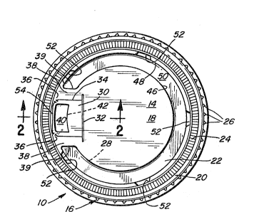
FIG. 1 i9 a plan view of a lid in accordance with the present
invention .
FIG. 2 is a fragmentary sectional view of the lid of the
present invention shown on an enlarged scale
~.ZI!~7~
~3--
taken substantially along line 2-2.
DETAILED DESCRIPTION OF PREFERRED EMBODIMENT
The invention is preferably embodied in a lid
10 for mounting on a drinking cup 12 (shown
fragmentarily in phantom in FIG. 2). Herein the lid
will be described in an orientation correspondinq to the
drawings, with terms such as "top" and "vertical" used
for reference purposes. It will be appreciated that
during use, the lid will typically assume various
orientations.
The lid includes a top wall 14 and a generally
frustoconical skirt portion 16. The skirt portion 16
extends radially outwardly and downwardly from the top
wall 14 and includes means for gripping the lip 17 of
the cup 12. The top wall 14 has a generally planar
central portion 18 and a generally circular
periphery 20. A generally C-shaped downwardly
projecting portion or channel 22 is located between the
central portion 18 and the periphery 20.
To aid in gripping of the lip of the cup, a
generally circular, generally frustoconical corru~ated
strip 24 extends about the circumerence of the top
wall 14, and the skirt portion includes a plurality of
flutes 26. As shown in FIG. 2, the corrugated strip 24
slopes upwardly and inwardly from the periphery 20 of
the top wall 14. The functions of the corrugated strip
24 and flutes 26 are descrihed in detail in
above-referenced U. S. Patent No. 3,583,596.
The lid 10 defines an axis--i.e., a line
through the center of the top wall 14 and perpendicular
thereto--which will be used herein for reference
purposes. The downwardly projecting portion or channel
22 provides a surface 28 facing radially inward for
engagement by a laterally moving finger ~not shown) in a
vending machine so that a lid on the bottom of a
vertical stack may be displaced laterally from the
stack by the finger so as to be positioned for placement
~8~
--4--
on a cup to be dispensed. The surface 28 is disposed at
a predetermined radius from the axis of the lid 10. In
the illustrated embodiment, this surface 28 is
perpendicular to the top wall 14.
The lid 10 herein includes a tab 30 which may
be folded downwardly to provide an opening 31 (FIG. 2)
for drinking from the cup 12 or for insertion of a
straw. In FIG. 2, the tab 30 is shown in a downwardly
folded configuration of FIG. 1 in solid lines, and shown
in the configuration in broken lines. The tab 30 folds
downwardly along a preformed fola line 32. The tab 30
is defined by a generally U-shaped slit 34 which is
interrupted at two points by bridges 36 (FIG. 1) between
the tab 30 and the adjacent portions of the top wall 14
so as to prevent accidental displacement of the tah 30.
In accordance with the invention, the slit 34
i 5 formed through generally planar portions 38 of the
top wall 14 which are coplanar with the generally planar
central portion 18 thereof, and which extend radially
outward from the central portion 18 between the ends 39
of the C-shaped channel 22; and the tab 30 has a
downwardly projecting boss 40 thereon havlng an inwardl~
facing sur~ace 42 disposed at the same ra~ius from the
axi~s of the lid as the inwardly facing surface 28, so
that the two ~ur~aces 28 and 42 together define a
noncontinuous surface of revolution about the axis of
the lid. More particularly, the surfaces 28 and 42
provide a substantially cylindrical surface interrupted
only adjacent the generally planar extensions 38 from
the top wall 14 which aefine gaps between the two
surfaces 28 and 42. When this substantially cylindrical
surface is engaged by a finger having a wid~h greater
than that o~ thes~ gaps, action of the finger on the
lid lO is independent of the angular orientation of the
lid. This enables the lids 10 to be handled
auto~atically within the vending machine without having
to be oriented in any particular direction.
. .
~28~1~7~
The channel 22 herein is defined by a
substantially vertical inner wall 46, a concentric
substantially vertical outer wall 48 and a substantiallv
horizontal bottom wall 50 extending therebetween. In
addition to providing the radially inwardly facinq
surface 28 on its inner wall 46, the channel 22 also
provides a receptacle for small amounts of liquid which
may slop onto the top of the lid lO.
One problem which may arise in the stacking of
lids 10 is that the lids may telescope and bind to one
another when the stack i5 compressed longitudinally. To
prevent such binding, minor variations are preferably
introduced into the configurations of different lids 10
so that adjacent lids are unlikely to be identical, and
interference will prevent a particular lid from
telescoping with an adjacent lid. Herein, the
variations take the form of indentations 52 in the outer
surface of the C-shaped channel 22.
The inner wall 46 is relatively stiff so as to
prevent excessive deformation of the inner wall 46 by
the finger, and is orien-ted vertically so that
horizontal force on the inner surface 28 does not tend
to cam the lid upward 9 as would horizontal force on the
inner surface of the frustoconical skirt portion 16.
The lid 10 is manufactured in a two-step
process, the first being a vacuum-thermoformin~
operation and the second bein~ a slitting operation to
define the tab 30. Provision of the planar
extensions 38 greatly facilitates the slitting operation
as compared with formin~ a slit on a nonplanar surface~
The slit 34 does not extend into the corrugated
strip 24, but is disposed entirely radially inward
thereof so as not to interfere with its gripping
function. When the lid 10 is placed on the cup 12, the
tab 30 is maintained in its closed position by the
bridges 36 and the lid is held tightly on the cup 12, so
that the possibility of accidental spillage is almost
8~7~
--6--
entirely precludea.
The radially outermost portion 54 of the
slit 34 is directly adjacent the inner diameter of the
corrugated strip 24. The proximity of this portion 54
of the slit 34 to the inner diameter of the corruqated
strip 24, in conjunction with the slope of the
corrugated strip 24, facilitates emptying of the
cup 12. If the cup i5 tilted so that the portion 54 of
the ~lit is at the lowermost part of t~e lid 10, almost
all of the liquid in the cup 12 will flow out through
the opening 31.
Frequently, a purchaser of a drink in a cup as
described above may abandon the cup or place it on the
floor of a vehicle therein. Should the cup become
positioned on its side, it is desirable that the
remaining liquid not spill through the drinking
opening 31. Positioning of the radially outer~ost
portion 54 of the slit 34 radially inwardly of the
corrugated strip 24 helps to prevent such spillage, as
the corrugated strip 24 acts to retain such residual
liquid within the cup.
Another feature of the lid 10 is that the tab
30 remains attached to the lid. In the past, openings
; in some lids have been ~ormed by completely removing a
portion of the lid. Similarly, bottles have removable
caps and many cans have removable tabs. Removable caps,
tabs, etc. contribute to unwanted litter, and some
states have laws prohibiting cans, etc., with throw-away
tabs. Thus, there is a need for lids of the type
described above wherein the tab remains connected to the
lid.
From the foregoing it will he appreciated that
the invention provides a new and improved lid for a
drinking cup. While a preferred embodiment has been
described and illustrated, the invention i5 not intended
to be restricted to this or any particular emhodiment.