Note: Descriptions are shown in the official language in which they were submitted.
~ 89~ 5
SPECI~ICATION
Tltle of the In~entlon:
METHOD OF PRODUCING A M~T CONSISTING
OF FI~AMENT l.OOP AGGP~EGATIONS
Thls lnvent~on rela~e~ to method of
producing a mat conslstlng of fllament loop aggregat-
10~5, which is a coarse net-llke developed resilient
mat madQ by complLcatedly entangllng synthetic resin
monofllaments and more particularly to .. method of
produclng a mat con~isting of fllament loop a~gregat-
lon~ and adapted to a porch mat of flxed dimention~
~r a fl~or mat formed and laid ln a lomg sheet.
Instead o~ a conrentlonal carpet mat or
synthetlc resln mat, there is recently provlded a three-
dimenslonal net-like mat conslstlng of synthetic resin
monof~lament~ hlgh ln the water permeabllity and qulck
dryablllty. Due to such char~cterlstlcs a~ the resill-
ency and weather-proofness, such three-dimensional
net-llke mat 18 ueed ln many lndoor and outdoor flelds,
i~ applled partlculsrly to such water uslng place as, for
example, an lnlet and outlet of a bath room or a pool ~lde
and 19 appreclated becaus~ lt 18 slmple to wash and dry.
~g
lS
Also, as this kind of three-dimensional mat
is open, the sand and gravels brough when it is trod
will drop down ~nd will not remain on the surface.
As water or the like also wlll drop down, the surface
can be always kept dry. It i8 thus convenient.
In addition, when such elastic sheet as a
synthetic resin sheet, foaming eheet or rubber sheet
is pasted to the lower ~urface of such mat, the cushion-
lng property as of a mat will be able to be ~ncreased,
the ~and and water dropping from the surface will be
able to be recel~ed by this sheet pasted to the lower
surface and the floor will be able to be prevented from
being made dirty directly by the dropping sand and
the l~ke,
Descript~on of the Pri~r Art;
As disclosed ln the gazette of a Japanese
patent publication No.14347/1972, such three-dimensional
net-like mat i8 .formed a~ a non-woven fabric wherein
many monofilaments made of a thermoplastic synthetic
resin are lamlnated whlle belng rubbed and bent, are
fused at thelr contaot polnt~ and are cooled to be
solidified,
The formation of upright loops disclosed in
the gazette of a Japanese patent publication No.31222/
1980 and a Japanese patent laid open No.85061/1987 i~
z 2 =
91S
known as a web forming means of the above mentioned
flilaments in such non-woven fabric.
Now, in the non-woven fabric formation by the
abo~e descr~bed cQnventional means, in ~uch rubbed and
bent web formation, the resiliency of the individuà~.
rubbed and bent filament form part itself is low,
the rubbed and bent filament~ by this producing means
overlap on each other to fall down and, as a result, as
the entangled density of the filaments becomes higher,
the resiliency of the sheet wlll be lost
~ hu~, when the mat i~ used, the treading touch
will be obstructed and, when the mat i8 stored or carried,
it will be difflcult to wlnd in the sheet-like mat,
much to the inconvenience
On the other hand, when the web formation is
made loop-~ike, the resiliency of the filament itself
in each loop-llke part will be developed but, in the
web made of arcuate loops arranged in a sub~tantially fixed
form, the respectlve loops are only fused at their
intersecting points and the contact point~ between the
ad~acent loops, are high ln the lndopendency and are
therefore low in the resiliency against treading and,
a~ ~ result, no favorable treading touch wlll be obtained.
Summar~ of the Inven_ion:
Therefore, the present lnvention has it as an
3 ~
~.2~ 5
object to provide method of producing a mat wherein a
filament web is foarmed of positively closed loops to
develop a filament resiliency in each loop part and
the degree of the contact f usin~ between the respective
loops is made high to be able to develop a strong sheet
resiliency.
Description of the Drawln~s.:
The many advantages and features of the present
invention can be best understood and appreclated by
reference to the accompanying drawings wherein:
~ ig. 1 i8 a side view of Qn essential part
showing an embodiment of the apparatus of the present
invention;
Fig. 2 i~ a slde view of an essential part
showing another embodlment of the method of the present
invention; and
~ ig, 3 i8 a ~heet producing process block
diagram by using the method of the pre~ent invention.
Detailed Descriptlon of the Inventlon:
According to the present lnventlon, a mat
i9 made by overlapplng a three-dlmen~ional aggregatlon
o~ upright disarranged loop-like synthetic resln
filaments and a ~ynthetic resln layer having very
few clearances or no clearance and has many spaces
wlthin the three-dlmen~ional aggregation of the ~ilaments
~ 4 ~
~ 5
to develop a cushioning property.
In order to produce such mat, several hot
filament~ of a thermoplastic synthetic resin are pressed
and extruded through die orifices and are made to fall
toward a water surface.
~ he falling hot filaments are heated by such
heat sources as ceramic far infrared ray heater3 so as
not to be cooled by the atmosphere.
Such hot filaments are easy to make coiled
loops on the water surface. Unless the filaments are
hot, the loops will become large, Further, in the
filaments of a reduced temperature, no coiled loop
will be formed but only a channeled rubbed and bent
form will be able to be made.
The height from the die mouth end to the
water surface i~ 5 to 100 cm. and the heat reduction
of the fllaments 19 prevented by making the die mouth
end approach the water surface as much as possible.
lhe oriflce diameter of the dle i8 0.3
to ~.5 mm. as an element determlnlng the fllament
diameter ln con~ideration of the shrlnkage of the
materlal at the time of hardening after being extruded
and molded, retains the resiliency and durability of
the formed fllaments and prevents the permanQnt set.
A mat sheet consisting of filament aggrega-
~ 5 =
s
tions of respectlve width~ can be made by arranging thenumbers of orifices corresponding to the widths of 90,
120 and 150 cm. of intended mat sheets with an orifice
arrangement of a die of 2 to 6 longitudinal rows
at the intervals of 3 to 5 mm. and a pitch of 3 to 5 mm.
in the lateral rows.
~ hat is to say, a hot first filament bundle
extruded out of the ~-die of such orifice arrangement
is made to fall uprlght toward cooling water and is
received by submerged rolls of a rotary peripheral
speed well slower than the falling speed to limit the
falling speed ln water and to give the filaments a
resistance toward the water surface from the above
mentioned rolls. Loops having a peripheral length of
the filament length corresponding to the difference
between the extruding speed of the respective fllaments
and the falling speed in water wlll be sequentially
continuously described to form a coll-llke flrst fila-
ment loop aggregation,
In the samQ manner, a second filament bundle
falling toward a conveyer present on the water ~urface
wlll be prevented by thl~ conveyer from sinking into
water and will form loop~ on the water surface to form
a ~econd filament loop aggregatlon con~isting of over-
lapped coiled loops controlled by the conveying ~peed
- 6 =
~ 9~ S
of the conveyer.
At this time~ ~n order to make it ea~y to
form loops in the fir~t filament loop aggregation and
to make bent irregular loop~, lt i8 effective to keep
boiling the cooling water ~urface on which the filament
bundle fall 9,
Thi3 boiling state vibrates the respective
ftlaments wound on the water ~urface. A~ a result,
entangled disarranged coiled 1OOPB will be induced on
the water surface.
In order to make the boiling state on this
water surface, it i8 important to keep the filament~
coming out of the die at a high temperature until
the li~uld level. Generally, when the filaments are
in contact with the atmosphere, the filament tempera-
ture will quickly reduce. The water surface heated
by the falling in water of the filament bundle kept
at a filament extruding molding temperature~of 200
to 150C, by the above mentioned heating treatment
to prevent air cooling in the filaments coming out of
the die will be in the boiling state. Therefore,
when the cooling water 19 kept at a high temperature
of 60 to 80C., thi~ bolling w~ll be made positive.
When the filaments are molded to be coiled
loop~ while kept at a hlgh temperature, the fu~ing
between the loops will be accelerated. Further, when
the cooling water i8 at a hlgh temperature, in case
the molded loops are pulled out into the atmosphere
by the guide rolls and are sent to the secondary process,
they will be able to be ea~ily dried with cool or hot air.
A filament loop aggregation in which the
coil density i8 made coarse by increasing the rotation
(pulling speed in water) of the rolls in water and
the conveyer speed ~ynchroniæed with it and is made
high by reducing the pulling speed i~ formed.
On the other hand, even if the thickness
width of the hanging first filament bundle i8 not
regulated, a three-dimensional formation of coiled loops
will be made but the ~i2e of the loops formed on the
li~uid surface wlll not be constant. ~herefore, a means
of regu~ating the thickness width of the filament bundle
functions effectively to form an intended uniform thick-
ness coiled loop aggregation.
For the second filament loop aggregation
fed onto one outside of the first filament loop aggre-
gation, a guide roller iB located ~u~t below the water
~urface on the other out~ide of the first filament
loop aggregation to regulate the position cf the first
fllament bundle sinking while describing loops and
therefore the thickness width of the filament bundle
= 8
s
in the posltlon on the water surface ~ust above the
gulde roller will be regulated a9 related w~th the
regulatlon below the water surface.
Such first and second ~llament loop aggrega-
tlons are proces3ed ln two parallel place~ and the above
mentloned rlrst aggregation 18 formed along one slde
surface of the abo~e mentloned second aggregatlon.
In ~uch formatlon, when the above mentloned
~econd aggregatlon 18 heated on th~ slde ~urface to
be about the fus~ng temperature, the fllaments on the
slde surface wlll soften to maka a 3ynthetlc resln
layer of a hlgh denslty by the lateral fall of the
loop~,
~ hererore, thls synthetic re~in iayer may be
the second fllsment loop aggregat1on ~ormed ln advance
a ~ynthetlc res~n ~ack sheet or net-sheet.
In molding ~nthetlc resins, the general tem-
perature as of the coollng bath 18 about 50.C. for PE
(polyethylene) and YP (polypropylene), about 10 to 40C.
for PVC (polyvlnyl chloxlde) and about 8~C. for PS
(po~ystyrene).
The surfacQ tenslon of water on PVC (polyv~nyl
chlorlde) i8 80 hlgh as to be about 60 to 70 dym,/cm.
that flne ilaments o~ an outslde dlameter less than
1mm. wlll be overlapped in turn above the water ~urface,
n 9 D
~ ~ 8~ 9~ S
the coiled loops formed here wlll be laminated in
several steps end wlll be cooled in water and there-
fore the obJect aggregat~ons coarse ln the loop olearance~
will not be obtained, Therefore, ln order to se~en-
tially slnk the colled loops by the fllament bundle
on the liquid surface, lt 18 effective to add a ~urface
active agent reduclng th~ 8urface tension of the cooling
bath.
~ mbodlments of the pre~ent invention ~hall be
expla~ned in the followlng:
bodlments:
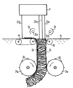
Fig. 1 is a slde ~iew showlng component parts
ln an optimum apparatu8 for embod~ing the present
inventlon. ~wo sets of filaments 2a and 2b are to
fall vertically toward cooling water 5 while being
molded ln the thickness direction (longltudinal d~rec-
tion) from a dle 1 extruding a thermoplastic synthetic
resln material under pressure.
In the lateral dlrectlon ~front to back direc-
tion of the paper 8urface) of the die in thi~ case,
many filaments 2a and 2b are to be molded as arranged
at predetermined interval6 (pltch of 3 to 5 mm.) in
the length 20ne correspondlng to the lateral width of
an intended moldlnB-
A conveyer 4 present on the water surface is
~ 10 .
arranged ln the falllng zone of the filamentR2b andi8 to be driven at a conveying speed equal to the
later described comparatively 910w water sinking speed
of the filament loop aggregation.
On the other hand, in the falling zone of
the filaments 2a, bar-llke ceramic far infrared ray
heaters 3a and 3b are arranged together with reflecting
plates 9 80 as to be heating heat sources.
On the fal~ing water surface of the filaments
2a, a guide roller 6 i9 arranged at a predetermined
spacing from the delivery end of the above mentioned
conveyer 4 90 that the bundle of the filament~ 2a may
fall on thè water surface in this clearance and may be
led by this roller 6 to sink down~
A pair of feedlng submerged rollers 7a and 7b
rotated and driven at a oonstant speed are arranged in
water to hold and contract the bundle of the filaments
2a having sunk in the above mentioned water and move
it in the cooling water 5. Many engaging pins 8 are
erected at intervals on the peripheral surfaae~ of these
submerged rollers 7a and 7b. As the rotating peripheral
speed of these rollers 7a and 7b rotating at a constant
speed is set to be lower than the falling ~peed of the
filaments 2a, the filament~ 2a falling at a high s~eed
from the die 1 will be decelerated in sinking in water
1 1 =
S
by the above mentioned submerged rollers 7a and 7b
and, as a result, will be relaxed by the filament
length corresponding to the dlfference betwee.n the
falling speed and sinking speed, ~hese relaxations will
concentrate in the water surface zone due to the buoy-
ancy of the filaments 2a of a small specific gravity.
As a result, the filaments 2a will form loops on the
water surface.
That is to say, the filaments 2a extruded
out of the die will reach the water surface o~ the
cooling water 5 while being kept near the temperature
at the time of molding by heating by the above mentioned
heaters 3a and 3b in the falling 20ne in air, ~he
filament~ 2a having sunk ~n the coollng water 5 will
~uickly lower in the temperature and wlll be hardened,
However, these hardened tilament~ 2a will be regulated
in the pulling amounts by the submerged rollers 7a and
7b stopped in sliding by the engaging pins 8, therefore
the hardened part~ in water will. be sub~ected to resis-
tances from the rollers 7a and 7b in water and thereby
the soft filaments 2a still at a high temperature
~ust before reaching the water surface will be curved
and will be gradually pulled into water while describing
100PB ta form co~led loops.
When the temperature within the bath of this
- 12 =
cooling watex 5 is kept at 60 to 80C., the cooling
water 5 in the falling position will be locally boiled
by heating by the filaments 2a reaching the water
surface while at a high temperature. By this boiling,
the water surface of that part wlll be waved and greatly
rocked and therefore the filaments 2a de~cribing loops
on this water surface will be waved and disarranged in
xesponse to the rocking of the water surface.
~ herefore, the total surface contact between
the ad~acent loops overlapped on the water surface will
be obstructed by the concavo-convexe~ by thls dis-
arrangement of the disarranged form loops and the
contact point parts will be comparatively many.
In such contact part, the loops will be fused
with each other between them and will be cooled to be
hardened. lherefore, coiled loops having comparatively
many fu~ed parts,'between the ad~acent loops will be
continuously formed ln turn and a filament loop aggre-
gation A in which colled loops a1 are cro~s-linked
longitudinally and laterally wlth loop edges overlapping
between ad~acent filaments 2a will be formed.
On the other hand, the other corresponding
filaments 2b will form on the falling water surface
loops by the filament length corresponding to the
difference from the extruding, molding an~ falling speed
= 13 =
~ .5
at the conveying speed at the conveyer 4 equal to the
sinking speed of the filament loop aggregation A regu-
lated by the above mentioned submerged rollers 7a and
7b and will be transmitted toward the falling zone of
the above mentioned filaments 2a while being laminated
in turn to be coiled on the conveyer 4. A filament
loop aggregation B high in the filament den~ity will
be formed by being fused in the coiled loop overlapping
parts by heating by the abo~e mentioned heater 3b while
the filaments 2b on this conveyer 4 are conve,yed, will
be well softene~ on the surface, will be conyeyed to
the dellvery end of the conveyer 4 and will sink into
the cooling water 5.
The sinklng zone in water o this aggregation
B is located on one out3ide of the falling ~one of
the above mentioned filaments 2a. ~he filaments 2a
falling between the aggregation B and the guide roller 6
on the opposite side will be regulated in the thicknes~
width by the aggregation B and guide roller 6. Therefore,
the size of the loops wlll be formed to be sub~tantially
constant and the softened surface of the above mentioned
aggregation B and the loops on one side of the aggrega-
tlon A will be fused together.
Thereby, there i8 formed a mat material
wherein the second filament aggregation B (lnathe
~ 14 _
laterally ~allen dlrection) hlgh ln the density 1~
overla~ped on one slde surface of the first filament
a~regatlo~ ~ (ln the uprlght dlrect~on).
By the way, a~ another embodiment, the above
mentloned hlgh den~ltly 3econd fllament aggregatlon B
need not always be formed slmultaneou~ly parallelly
wlth the aggregation A. As shown in Flg. 2, the a~gre-
gation ~ formed ln advance may be fed onto the conveyer 4.
As of a thermplastlc ~ynthetlc resin of a ~igh den~lty,
a back sheet made o a ~ynthetic re~in fllm.or net-
sheet madc of synthet1c re31n may ~e fed lnstead o~
thls ag~re~atlon B. In tha embodiment shown in the
above ment~one~ Plg. 2, tha ~ame mechanl~m part3 as ln
the embodlment shown 1~ the a~ove mentioned Ftg. 1
shatl bear respectlvely c~mmon reference numerals~
In these respectivQ embodlmente, the co~veyer 4
has lts conveylng ~urface set to be substantlally flu~h
wlth the water qurfacc but may be arranged to have lts
conYey1ng surface 80mewhat lncllned to be submerged
at the dellvery sidQ tlp.
~ y th~e wag, ln order to pull the colled
loops formed on the coollng water surface into water
without dl3turblng thelr form, a surface active agent 19
added lnto coollng water 4.
~- î S 8
s
Amounts of addltion of the surface active
agents per 100 parts of water:
Anion system: Alkylbenzenesulfonate 1 to 0.2 part
~ialkyl~ufosuccinste 1 to ~.0~ "
Nonionic syYtem: Polyoxyethylene nonylphenol ether
1 to 0.1 "
It is effective to add 0.05 to 0.2% dlalkyl-
sulfosuccinate which i9 high in the capacity of reducing
thesurface tension and in the connecting effect with a
81 i ght amount.
Now, in this kind of apparatus, in order to
keep the cooling bath level constant, cooling water is
circulated with a pump while being overflowed. In such
case, many bubbles will be generated in an aux~liary
tank le~el ~etecting e~ectrode and cooling bath and
will be disadvantageous in molding. In thl~ re~pect,
at the above mentioned effective component concentra-
tion of the dialkylsulfosuccinate, many bubbles tend to
be generated. Therefore, it can be said to be optimum
to add and use preferably 0.05 to 0.2% dialkylsulfo-
succinate.
The mat material conYiYting of the thus
formed filament loop aggregations A and B may be coated
wlth a pla~tiYol made of the same material mixture as
of the f'ilament to prevent the bonding strength reduction
, 16 =
s
and permanent ~et of the ~ilament loop~,
The apparatus formatlon therefor 19 shown in
~g. 3, An aggreeat1~n A p~lle~ up from a bath 10 ~f
the above mentloned coolln~ water 5 19 fed into a
prlmary dryer 12 by a feedlng roller and i8 drled at a
low temperature. In th1s drying, th~ aggregat10n A
18 stlll a~out 70C. by the coollng water 5 at a high
temperature. Therefore, the water can be comparatively
easlly and poslt~vely remoYed by blowing warm wind or
the llke.
The dr~ed aggregatlon A 19 ~ed lnto a surface
coatlng process part 13 by the above mentloned pla3ti901,
18 processed ln the part 13 by ~uch means as blowing,
palntlng or d~pp~n~ t~en fused by high temperature
dryln~ ln ~ secondary dryer 14 and 18 wound up on a
wlnder 15. A b~ck sheet conslstlng o~ a resln sheet,
foamed sheet~ rubber sheet or net-sheet may be used
as bonded to the bac~ surfacQ of thl~ aggregatlon A
ln re~ponse to the ob~ect of use of the mat or sheet.
(Formatlon Example 1)
Polyvlnyl chlorid~ (PVC)~P-l300)100 parts
Plastlclzer DOP Dloctyl phthalste 50
Stablll~er Dl~ut~l tin laurate 2
Csdmlum ~tearate 0.6 part
" ~arlum ~tearatQ 0.4
Colorlng agent 0,1
~ 17 ~
A compound material of the above mentioned
mixture i9 molded to be filaments by an extruding
molder.
~ he di~tance between the conveyer 4 below the
cooling water surface and the guide roller 6 is set
to be 15 mm. ~he distance between the guide roller 6
and submerged roller 7a i~ 9 mm. ~he filament molding
orifice dlameter o the die 1 i~ 0.8 mm. ~he d~e
orifice arrangement i~ of four longitudlnal rows.
~'he clearance between the filament 2b orifice and
filament 2a orlflce i3 50 mm, The clearance between
the fllaments 2a^is 4 mm. ~helr lateral orifice pitch
8 5 mm. ~he ~tance between the die and cooling water
~urface ~3 5 cm.
~ he die temperature ~ 8 185~C, The die pressure
i9 90 kg./cm2. The extruding pressure i~ 190 kg./cm2,
The cooling watèr temperature i9 60 to 80C. ~he guide
panel temperature is 120C. ~wo ceramic far infrared
ray heaters of 2.5 KW each are used. At a molding
linear speed of 2m. per minute, loops at a speed of
40 cm. per minute can be made.
In this ~ormation, by only holding the fila-
ment bundle in ite thickness width dlrectlon wlth the
guide roller~, the front and back surfaces of the aggre-
gat~ons can be unifarmed and a mat of a ~1ame~t diameter
= 18 =
3 ~ 3~
of 1 mm., loop size of 5 to 10 mm. and thickness of
14 mm. i8 obtained and is made a product through drying
and bonding ~teps.
(Formation Example II)
When, in the conditions of ~ormation Example I,
the filaments 2b are in two rows at a spacing
of 4 mm.,
the filaments 2a are in two rows at a spacing
of 4 mm. and
the di~tance between the filaments 2a and 2b
i9 45 mm,
a thick mat of the above mentioned second
aggregation layer B part of a fllament diameter of 1 mm.,
loop ~ze of 5 t~ ~0 mm. and thicknes~ of 14 mm i~
obta~ed.
~Format~on Example III)
When, ln the conditions of Formation Example I,
the filament~ 2b are in two rows at a spacing
of 4 mm.,
the filaments 2a are in two rows at a spacing
of 4 mm.,
the distance between the filaments 2a and
2b is 4~ mm. and
the distance between the conveyer 4 and
guide roller 6 is 17 mm.,
Y 19 =
.,
a thlck mat of a filament diameter of 1 mm.,
loop size of 5 to 10 mm. and thickne~ of 16 mm. is
obtained.
(Effects of the Invention)
Thus, according to the method of the present
invention, as an aggregation i8 formed of irregular form
loops by windlng filament~ to be coil-like, the indivi-
dual closed loops well develop the filament resiliency,
are of such lrregular form as a wavy form and are
therefore hlgh in the degree of contact fuslng between
the ad~acent continuous colled loops and between the
loop forming filaments arranged longitudinally and
laterally and thu~ a mat high in the bonded degree
as a whole can be obta~ned. In the aggregat~on part
in which such loop~ are formed in the upright direction,
in addltlon to the resiliency of the above mentioned
loops themselves, a stiff mat resiliency can be obtainsd
by the strength of the bonded degree between these
loops The hlgh density thermoplastic synthetic resin
layer is high in the strength, particularly, in the
tensile strength. ~herefore, according to the method of
the present invention, there can be obtained a mat
material high in both resiliency and tensile strength
and optimum to be used for a porch mat or fioor sheet
very high in the treading touch.
- 20 -
In the method of the present inventton, the
filaments are lowered onto the water surface while near
the molding temperature and, when this water surface is
waved by boiling, the loops formed on the water surface
will be able to be in such irregular forms as wavy forms
and to be contact-fused ln the loop intersecting parts
and between the loops.
When the second filament loop aggregation is
made a high density thermoplastic synthetic resin layer
simultaneously in parallel with the formation of the above
described first fllament aggregation low in the filament
density, the above mentioned long mat material can be
continuously formed. ~owe~er, simply, the above mentioned
second aggre~ation or back sheet mater~al formed in
advance or net-sheet may be used.
In addition, there are auxiliary effects that,
when the filament bundle falling toward the coollng water
surface i8 regulated ln hte direction of contracting
from outside the width of the thickness directlon of the
bundle, the sizes of the respective loops formed of these
filaments will be able to be uniformed and, when the
contracted width is controlled, the formation of combin-
ing the above described upright directed loops and laterally
fallen loops will be able to be freely made.
If the distance from the dle to the cooling
. .
il 2~
water surface is long, the filament temperature will be reduced
by air cooling between them. Therefore, it is desirable to
set the distance to be as short as possi~le. However~ if they
are to adjacent, the loop formation on the water surface will
be disturbed. Therefore, this distance of 5 to 10 cm. is
effective.
sy keeping the temperature of the cooling water at
a comparatively high temperature of 60 to 80C., a local boil-
ing state in which the water surface on which the filaments
fall is properly waved by heating by the filaments submerging
into water can be automatically obtained. In order to smmooth-
ly sink the filaments to prevent the loop forms being disturb-
ed, it is effecti~e to ad~ a surface active agent.
_ 22 =