Note: Descriptions are shown in the official language in which they were submitted.
1~ 9~33
- 1 -
NAR~OW-BAND WAVELENGTH SELECTIVE
OPTICAL COUPLER
Technical Field
This invention relates to the field of optical devices for coupling optical
5 signals from one optical fiber to another.
Background of the Invention
Optical ~lbers are being widely utilized in various communication systems
such as local area networks, computer networks and standard subscriber loops.
While optical ~lbers are capable of carrying a large amounts of information, the10 fibers lose their attractiveness unless there is some way to extract the
information from the fiber for the end-user.
Couplers and, in particular, directional couplers have been developed
exactly for this purpose. Directional couplers such as those described in U. S.
Patents 4,307,933, 4,317,614 and 4,431,260 include primary and secondary
15 optical fibers each having polished flat surfaces in contact in the presence of an
index matching fluid to accomplish evanescent directional coupling. In these
couplers, optical signals are coupled from the primary fiber into the secondary
fiber and the optical signals propagate in the secondary fiber in the same
direction in which the signals travelled in the primary fiber. Also, the coupling
20 is broadband in nature. That is, some percentage of each and every optical
signal in the primary fiber are coupled into the secondary fiber regardless of
mode or wavelength. Hence, directional couplers as described above lack
wavelength selectivity which is necessary for applications such as multichannel
wavelength division multiplexing and coherent communication systems.
Wavelength selective optical couplers have been predicted and described
for embedded (side-by-side) channel waveguides devices by N. Imoto in Jour. of
Li~htwave Tech.. Vol. LT-3, No. 4, pp. 8~S et seq. (1985). The couplers
proposed therein are contradirectional because optical signals propagating in the
primary waveguide at a particular narrow set of wavelengths are coupled to the
1288~83
secondary waveguide by a grating fiber to propagate in
opposite (contrary) direction therein. It should be noted
that Imoto stresses the importance of fabricating the grating
filter over the secondary (output) waveguide to reduce
undesired coupling between the embedded waveguides. While
this type of coupler is applicable to the wavelength division
multiplexing problem, it requires a complete change of trans-
mission medium from fiber to embedded waveguide and then back
to fiber and, in making those changes, it imposes significant
insertion losses on the communication system as a whole.
Summary of_the Invention
In accordance with the principles of the present
invention, it is possible to overcome the problems of the
prior art while achieving narrow band, wavelength selective
contradirectional coupling suitable for use in such
applications as wavelength division multiplexing/de-
multiplexing.
In accordance with one aspect of the invention there is
provided an optical signal coupler comprised of first and
second optical fibers, each fiber having a core region and a
cladding region surrounding said core region, said first and
second optical fibers being in substantially close proximity
of each other in a predetermined region to provide evanescent
coupling therebetween, the coupler being characterized by,
filter means positioned solely in the cladding region of said
first optical fiber in said predetermined region for causing
said coupling to be wavelength selective for one wavelength of
a plurality of wavelengths and contradirectional from the
first optical fiber to the second optical fiber.
Brief Description of the Drawinqs
A more complete understanding of the invention may be
obtained by reading the following description of a specific
illustrative embodiment of the invention in conjunction with
the appended drawings in which:
FIG. 1 shows one illustrative embodiment of the invention
utilizing optical fibers as the transmission media and a
grating-type filter, and
~ ~ .
c
~2~3~3983
2a
FIG. 2 is a graphical representation of the coupling
ratio for the signals reflected and coupled by the filter for
the embodiment shown in FIG. 1.
Detailed Description
Wavelength division multiplexing/demultiplexing systems
require the use of wavelength selective devices to extract a
predetermined wavelength or group of wavelengths from the
primary transmission medium. The present invention is a
narrow-band, wavelength selective optical coupler which is
well suited for such an application.
~2~39~33
- 3 -
In accordance with the general principles of the invention, the
wavelength selective optical coupler is comprised of first and second optical
transmission media, and a filter both disposed directly directly on the ~lrst
optical transmission medium and positioned between the first and second
5 optical transmission media. The first and second optical transmission media are
preferably in close proximity to one another in at least the region containing the
filter to enhance the filter operation of coupling a preselected wavelength
optical signal in a substantially narrow band from the first optical transmission
medium to the second optical transmission medium.
In the operation of this device, the optical signal ~;" propagates in the
first transmission medium toward the filter. When optical signal ~in interacts
with the filter, optical signal ~l? is coupled across to the second optical
transmission medium in a direction opposite to optical signal ?~;". The filter is
realized in a manner that it causes efficient coupling of optical signal ~6 into the
15 second optical transmission medium while keeping the back reflected optical
signal AD in the first optical transmission medium sufficiently separated in
wavelength from the optical signal at ~E.
~ oupling between the transmission media is primarily evanescent in
nature. By positioning the first optical transmission medium in close proximity
20 to the second optical transmission medium, evanescent coupling is made
possible. The narrow band filter then permits coupling of only a predetermined
wavelength in the narrow bandwidth into the second optical transmission
medium.
The first and second optical transmission media are realizable in various
25 ways. Optical fibers, both multimode or both single mode or a combination of
multimode and single mode, are one clear candidate for realizing the optical
transmission media. Also, polarization maintaining fibers are can be used for
one or both optical transmission media. An alternative approach is to employ
semiconductor waveguides grown one atop the other.
For optical fibers, evanescent coupling is accomplished by standard
techniques such as bending the fibers over a curved surface and creating a
smooth flat surface on each fiber such that the flat surface extends to a
sufficient depth through the cladding region to be near the core region. The
coupling efficiency of a resulting coupler depends on the distance between the
~8139E~3
flat surface and the fiber core region. Details concerning the procedures and
consicderations for lapping optical fibers in preparation for making an evanescent
coupler are provided by U. S. Patents 4,307,933, 4,317,614 and 4,431,260.
Realizations of the filter may take several different forms. For example,
5 diffraction gratings may be deposited on, placed in contact with, or formed
integrally with the optical transmission medium. An integrally formed
diffraction grating is preferable from a coupling efficiency standpoint because
there is no boundary between the grating and the polished flat surface of the
fiber in which the grating is formed and because the grating is in closer
10 proximity to the fiber core region than for a deposited grating. The shape ofthe grating perturbations can be rectangular, sinusoidal, trapezoidal, sawtooth,triangular or the like and is chosen as a function of processing technique used to
fabricate the grating. The period of the grating, 1~, and the effective interaction
length determine the bandwidth of the filter response. The length of the
15 grating is chosen to correspond to the length of the polished flat surface on the
optical transmission media and is alternatively known as the interaction length.It should be clear to those persons skilled in the art that the filter,
especially a diffraction grating type of filter, introduces a matching between the
first and second optical transmission media in the interaction region where both20 media are in close proximity. Hence, in all embodiments of the invention, it is
preferred that the first optical transmission medium differs from the second
optical transmission medium with respect to propagation constants or the
corresponding effective refractive indices. In optical fibers, dissimilarity can be
introduced by polishing identical fibers to different depths with respect to the25 core region, or by polishing different fibers to the same or differing depths, or
by using fibers having differing index profiles, or by employing a clispersion shift
in one fiber with respect to the other, or the like.
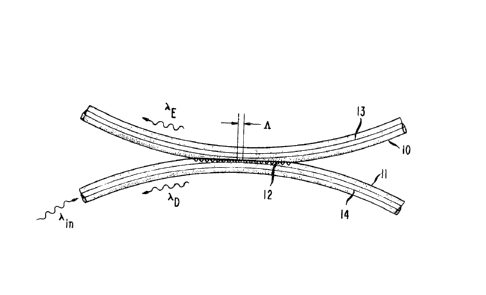
In an example from experimental practice, a narrow-band, wavelength
selective coupler is shown in FIG. 1 and is realized using optical fibers 10 and 11
30 as the optical transmission media and an integral Bragg reflection grating 12 as
the filter.
Optical fibers 10 and 11 are single mode optical fibers having core regions
13 and 14, respectively. Each fiber is bent over an arcuate shape and polished
to a flat surface to differing depths with respect to the core region resulting in
~2~
~ 5 -
differing effective refractive indices for the fibers in the interaction region where
the fibers are in close proximity. The effective refractive index for optical fiber
11 (the input fiber for the coupler) is denoted N,; the effective refractive index
for optical fiber 10 (the output fiber for the coupler) is denoted N2.
Bragg dif~raction grating 12 having a grating period 1~ is formed in the
interaction region of optical fiber 11 into the flat surface previously polishedthereon. Using standard processing techniques, a thin layer of photoresist is
deposited over the polished surface of optical fiber 11. A Bragg reflection
grating mask is then written onto the photoresist by a standard holographic
10 interference technique. Reactive ion etching is employed to produce the Braggdiffraction grating directly in the interaction region of optical fiber 11. In this
example, the Bragg diffraction grating was etched approximately 800 Angstroms
into the optical fiber with a grating period A of 0.53 ,um. to permit phase
matching between optical fibers 10 and 11 at a center wavelength of 1.5C ~m. as
15 determined by the exchange Bragg condition ~E = (Nl + N2)1~.
After fabrication of the Bragg reflection grating 12 is completed, the
polished flat surface of optical fiber 10 is placed against the grating 12 in optical
fiber 11.
In operation, an optical signal represented by ~in is launched into the
20 input of the coupler, optical fiber 11. As the input optical signal interacts with
the Bragg reflection grating 12, an exchange Bragg reflected optical signal at
wavelength ~E iS coupled into the output of the coupler along a contrary
direction in optical fiber 10. Concurrently, a direct Bragg reflected optical
signal at wavelength ~D = N, A propagates in a contrary direction along optical
25 fiber 11.
As shown in FIG. 2, under normal operat;ng conditions the coupler
exhibited a contradirectional coupling of 255~ (curve 21) and a full wave half
maximum of 6 Angstroms around the exchange Bragg reflected wavelength.
The coupler also exhibited a direct Bragg reflected component at ~D with a 9%
30 coupling ratio (curve 22 is plotted on a different scale than curve 21) and a full
wave half maximum of 4 Angstroms.
Performance of the coupler in the interaction region is improved by
utilizing an index matching fluid between the flat surface of optical fiber 10 and
the Bragg reflection grating 12 in optical fiber 11.