Note: Descriptions are shown in the official language in which they were submitted.
39~35
ENERGY A~SORBING BARRIER
BACKGROUND OF THE INVENTION
Field of_the Invention:
The present invention relat~s to an energy ab~
sorbing barrier, and more particularly to an energy ab-
sorbing barrier adapted for dissipating kinetic energy
upon impact by a moving vehicle.
Description of Prior Art:
Energy absorbing barriers are in common use
for many vehicular traffic applications. Those of a
semipermanent nature are heavy, difficul~ to install
or are expensive to maintain. Barriers of this type
include fixed guard rails, concrete median barriers,
and special structures located in a protective array
around highway signs, bridge ~butments and the like.
Lighter, more portable structures are less likely to
absorb as much impact energy, but they are more easily
installable for defining temporary traffic lanes,
closing off highway construction sites, establishing
pedestrian walkways, etc.
A typical highway barrier comprises elon-
gated, blocks of concrete arranged end~to-end to
~U39~5
-- 2 --
intercept vehicles leaving a defined traffic lane.
They physically redirect the path of the vehicle and
can develop severe impact forces on the vehicle occu-
pants. Further, the side walls of the barrier slope
downwardly and outwardly to provide a rela~ively wide
base to make the barrier difficult to overturn, but
this also provides a climbing surface for the vehicle
tires and a vehicle has a tendency to climb and vault
the barrier and pass into oncoming traffic lanes or
into other restricted areas.
Regardless of their shape or constructionr
most such barriers are made non-resilient, massive and
heavy in order to positively stop vehicles. Of
course, this is potentially very dangerous to the ve-
hicle occupants. There are some barriers of the priorart designed to progressively absorb kinetic energy
and thereby gradually decelerate a vehicle, but such
barriers are typically relatively complex or expen-
sive. Some are characterized by internal chambers
filled with gas, li~uids or other fluent mat~rials.
Others depend upon springs or internal shock absor-
bers. Regardless of their construction, such barriers
are usually not readily adapted for interconnection to
define a vehicle lane, or are characterized by side
walls undesirably providing sufficient tire traction
that vehicles can climb and vault such a barrier.
SUMMARY OF THE INVENTION
According to the present invention, an energy
absorbing barrier is provided for dissipating kinetic
energy upon impact by a moving vehicle. The barrier
12~8985
includes walls defining an interior chamber adapted to
be filled with water. The unfilled barrier is rela-
tively light and easy to transport to and from ~he
place of use, while the filled barrier is sufficiently
heavy to resist overturning on vehicle impact. The
end walls include fittings for end coupling one bar-
rier to another in a string to define a traffic lane,
and also render the assembly virtually impossible to
overturn.
The barrier side walls are made of a material
having a relatively low coefficient of friction. The
walls are resiliently deformable for resumption of
their normal shape after being struck and deformed by
a moving vehicle, and are characterized by a pattern
of deformation which tends to trap and slow vehicle
tires.
The barrier may be provided with fencing or
similar supplemental structures to define a higher
barrier, it can be provided with transverse or elon-
gated reinforcing elements for reinforcement againstundue flexure, and it can be provided with auxiliary
bias means such as springs to further assist in absorb-
ing vehicle impact and the like.
Certain embodiments of the barrier are config-
ured to mount on one or both sides of usual median bar-
riers. This provides supplemental vehicle impact pro-
tection, rather than providing a substitute for the ex-
isting median barriers.
g~
Other objects and features of the invention
will become apparent from consideration of the follow-
ing description taken in connection with the accompany-
ing drawings.
BRIEF DESCRIPTION OF THE DRAWINGS
FIG~ 1 is a perspective view of an energy ab-
sorbing barrier according to the present invention,
the barrier being illus~rated as connected at one end
to a like barrier to define a race course;
FIG~ 2 iS a side elevational view of the bar-
rier of FIG. l;
FIG~ 3 is a view taken along the line 3-3 of
FIG~ 2;
FIG~ 4 iS a detail longitudinal cross-sec-
tional view of the pin coupled portions of adjacent
barriers;
FIGo 5 is a partially diagrammatic top plan
view of barriers connected by couplers to form one
side of a race course turn;
FIG~ 6 iS a view similar to FIG~ 5, but illus-
trating use of differently configured couplers to
orient the barriers in a generally serpentine, zigzag
configuration;
FIG~ 7 iS a viéw similar to FIG~ 6~ but illus-
trating use of yet another configuration of coupler to
orient the barriers in adjacent, "stacked" relation;
FIG~ B is a perspective view of a typical
coupler;
FIG. 9 is a generally diagrammatic side ele-
vational view, on a reduced scale, of a barrier fittedwith an overflow compartment or diaphragm;
lX~8~
FIG. 10 is a view similar to FIG. 9, but
illustrating a barrier fitted with a means for using
the contained liquid for fire fighting or the like;
FIG. 11 is a side elevational view of end
coupled barriers provided with expanded metal screen-
ing surmounting the liquid fillable portion of the
structure;
FIG. 12 is a view similar to FIG. 11, but
illustrating utilization of poles and interconnecting
barrier wires instead of metal screening;
FIG. 13 is an enlarged cross-sectional view
taken along the line 13-13 of FIG. 11;
FIG. 14 is an enlarged view taken along the
line 14-14 of FIG. 12;
FIG. 15 is a view similar to ~IG. 14, but il-
lustrating an I-beam form of longitudinal connector,
rather than the strap connector illustrated in FIG.
14;
FIG. 16 is an enlarged view taken along the
lines 16-16 of FIG. 11, and particularly illustrating
employment of a metal drain plug in the plastic mater-
ial of the barrier;
FIG. 17 illustrates a form of filler cap a-
dapted to store a collapsible bag which is outviardly
deployable by liquid driven from the barrier;
FIG. 18 is another embodiment of the barrier
of FIG. 1, but provided with an overlying thin sheet
metal covering to resist tearing of a barrier made of
plastic material;
FIG. 19 is an end elevational view of a pro-
tective cover like that of FIG. 18, but adapted to
overlie both sides of the barrier;
FIG. 20 is an enlarged view taken along the
line 20-20 of FIG. 18;
~2~85
FIG. 21 is an end perspective view of a pair
of barriers like that of FIG. 1, and coupled together
for common movement by a special end fitting or
coupling;
FIG. 22 is a top plan view schematically
illustrating end connection of three barriers by the
end fittings of FIG. 21;
FIG. 23 is a view similar to FIG. 21, but
illustrating a pair of end couplings spaced apart by
biasing means;
FIG. 24 is a view similar to FIG. 22, but
illustrating the end fittings or couplings shown in
FIG. 23;
FIG. 25 is a schematic top plan view illus-
trating a form of T-connector adapted to couple to-
gether a pair of longitudinally oriented barriers with
a transversely oriented barrier;
FIG. 26 is a schematic plan view of a plur-
ality of end connected barriers, the end one of which
is provided with a protective end cap for absorbing
the force of an end impacting vehicle, for example;
FIG. 27 is a view similar to FIG. 26, but em-
ploying a protective end cap attached to the ends of a
pair of divergent strings of end connected barriers;
FIGS. 28, 29 and 30 are end elevational views
of different end connectors for connecting together
barriers to accommodate a slope of a supporting sur-
face, or to enable a reversal of the lateral orienta-
tion of the barriers;
F~G. 31 is a perspective view of a convention-
al concrete median barrier and a barrier of the pre-
sent invention which includes an attachment connector
for end coupling of the two, the components being
shown in exploded relationship for clarity;
~2~985
FIG. 32 is a transverse cross-sectional view
of a conventional concrete median barrier provided
with another embodiment of the present barrier, this
embodiment constituting a form of half section to
overlie one side of the concrete barrier;
FIG. 33 is an enlarged view taken along the
line 33-33 of FIG 32;
FIG. 34 is a view similar to FIG. 32, b~it il-
lustrating a pair of the half barriers of the embodi-
ment of FIG. 32, and overlyins both sides of the con-
crete barrier;
FIG. 35 is a top plan view of yet another em-
bodiment of the barrier of the present invention, the
barriers of F~G. 35 being characterized by a dovetail-
lS ed end connection and specially tapered end barrier;
FIG. 36 is a view taken along the line 36-36
of FIG. 34;
FIG. 37 is a view taken along the line 37-37
of FIG. 37-37 of FIG. 35;
FIG. 38 is a view similar to FIG. 13, but il-
lustrating an integrally molded reinforcement of the
barrier which serves as a substitute for the cable of
FIG. 13;
FIG. 39 is a perspective view of the ends of
a pair of laterally spaced apart barriers, such as
those shown in FIG, 23, but showing another form of
end connector or coupling;
FIG. 40 is an enlarged view taken along the
line 40-40 of FIG. 39;
FIG. 41 is a view similar to FIG. 13, but
illustrating another embodiment of the barrier, and
which is characterized by a vertically extending
central core fillable with concrete, earth or the
like;
~ 128~3985
-- 8
FIG. 42 is a perspec-tive view of yet another
embodiment of the yresent barrier, the barrier of FIG. 42
being characteri~ed by sloping sides absent the traction
spoiler channels seen in the embodiment of FIG. 1;
FIG. 43 is a view similar -to E'IG. 27, but
illustrating employment of the T-fitting of FIG. 25;
FIG. 44 is a view similar to that of FIG. 25, but
illustrating end connec-ted barriers spaced apart and
connected together by end connected transverse barriers;
FIG. 45 is a perspective view of a hanger bracket
for attachment to a barrier for suspending a protective
covering or sign or the like adjacent -the barrier side;
FIG. 46 is a perspective view of a -typ1cal dolly
for transporting a barrier;
FIG. 47 i.s a side elevational view of the dolly of
FIG. 46;
FIG. 48 is a view similar to FIG. 34, but utili~ing
a different form of half barrier not requiring the support
pedestal of the embodiment of FIG. 34;
FIG. 49 is a perspective view similar to FIG. 1,
but employing superjacent upper barriers surmounting the main
or lower barr~ers;
FIG. 50 is an end elevational view of the barrier
of FIG. 1, diagrammatically illustrating the successive
losses of traction by a vehicle tire as i-t encounters the
vertically spaced apart tracti.on spoiler channels;
FIG. 51 is a view similar to FIG. 50, illustrati.ng
a vehicle tire in full line and phantom line positions, the
phantom position illustra-ting the loss of tracti.on at the
lowermost traction spoiler channel;
FIG. 52 is a view similar to FIG. 51, illus-
trating deformation of the barrier of FIG. 1 by an
essentially laterally travelling vehicle tire;
FIG. 53 is an enlarged view taken along the
line 53-53 of FIG. 52;
FIG. 54 is a view similar to FIG. 52, and
illustrating the manner of deformation of the barrier
of FIG. 1 by ~ vehicle tire travelling approximately
at a right angle to the barrier side; and
FIG. 55 is a transverse cross sectional view
of a further embodiment of the present barrier, with a
different !~ide wal.l and upper portion configuration;
FIG. 56 is a view similar to FIG. 35, but
illustrating a differen~ barrier configuration; and
FIGS. 57-~0 are partial transverse cross
sectional views of yet other embodiments of ttle pre-
sent barrier, each illustrating a different b~rrier
configuration.
DESCRIPTION OF THE PRF.FERRED EMBODIMENTS
Referring now to the drawings, and particu-
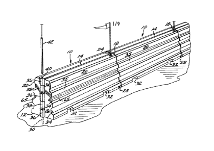
larly to FIG. 1, there is illustrated a barrier 10
according to the present invention and comprising,
generally, an elongate container having a flat base
12, a top 14, a pair of end walls 16 and 18, and a
pair of side walls 20 defining an interior chamber 22,
as best seen in the cutaway showing in FIG. 3.
The barrier container includes a fill opening
which is normally closed by a bung or cap 24, as gener-
ally indicated in FIG. 1. Ballast such as water 26 or
other fluent material can be admitted through the fill
12~1~398~;
-- 10 --
opening to partially or completely fill the interior
chamber 22, as will be seen. Suitable drain openings
closed by threaded plugs 28 or the like are located at
the bottom of the chamber 22 adjacent the base 12.
The base 12 is adapted to be placed upon any
suitable supportiny surface such as the ground or pave-
ment. It can be fixed to the ground, as will be seen,
or fixed to a struc~ure embedded in pavement, such as
to the cylindrical receptacle shown in dotted outline
at 30 in FIG. 1.
The barrier 10 is widest at its base 12, and
the side walls 20 slope upwardly and inwardly to form
a generally horizontally oriented and narrow top 14.
The barrier 10 is preferably molded of a plas-
tic material characterized by high strength, resil-
ience, and resistance to permanent deformation, such
as a cross-linked polyethylene material. A very impor-
tant characteristic of this plastic material is its
low coefficient of friction or slipperiness, as will
be seen. A suitable material for the barrier 10 is
available under the trademark MARL~X CL-100 from
Phillips Chemical Company of Bartlesville, Oklahoma.
It provides high impact resistance at cold tempera-
tures, excellent tensile strength, and resistance to
weathering because of included antioxidants and ultra-
violet stabilizers.
The material is characterized by a relatively
low coefficient of friction and good flexure. Conse-
quently, in wall thicknesses such as are preferably
12~89~35
used in the barrier 10 and its variants, a tire will
typically deform the barrier and slide along its
length, developing a bulge or traveling wave of side
wall material which tends to trap, capture and slow
the vehicle tire. This phenomenon permits more grad-
ual slowing of the Yehicle, while the slippery quality
of the barrier side wall tends to prevent the tire
from climbing out Gf its captured state. As will be
seen, various barrier side wall configurations are
hereinafter set forth to best capitalize on this
characteristic.
A barrier made of such material is relatively
light in weight, an empty or unfilled barrier 10 ap-
proximately 33 inches high, 60 inches long, and mea-
suring 24 inches at the base, weighing approximately100 pounds. Two men can easily lift such a barrier
and arrange a number of the barriers in end-to-end re-
lation to form pedestrian lanes at movies, amusement
parks, or wherever people must line up for some pur-
pose.
A barrier of the above dimensions completelyfilled with water weighs approximately 1250 pounds.
This weight, plus the truncated configuration of cer-
tain embodiments of the barrier, makes it very diffi-
cult to overturn.
The barrier is transportable by a forklift orthe like, the lift fork being receivable within re-
cesses 32 molded into the base 12, as best seen in
FIGS. 1 and 2.
12~389~35
- 12 -
The energy absorption properties of the bar-
rier 10 is adjustable varying the materials of which
it is made, or by varying its configuration or dimen-
sions, including its wall thicknesses. Such proper-
ties are also affected by the type of ~luid fillingmaterial, and the degree of fillingl that is, the pro-
portion of liquid to air. A barrier partially filled
with water includes a relatively large air space with-
in which the water may flow on impact, and the air
acts in the manner of a gas accumulator. A completely
filled barrier is relatively incompressible except
through liquid escape through the fill opening, and
deformation of the barrier structure.
The dimensions of the fill opening can be
arranged to provide a relatively rapid escape of
water, or a metering arrangement can be provided to
more gradually dissipate impact kinetic energy, as
will be apparent. The manner of empirically adjusting
these factors to provide a desired rate of energy dis-
sipation will be immediately apparent to those skilledin the art and a discussion thereof is omitted for
brevity.
The relative resilience o the FIG. 10 bar-
rier is important. It must retain its shape when fill-
ed, it must be resilient enough to resume its shapeafter it has been deformed by a moving vehicle or the
like, and it should be resilient enough to form a
deformation bulge ahead of an impacting vehicle tire
to slow its progress and prevent it from climbing the
barrier.
39l~S
- 13 -
An important feature of the side walls 20 of
the embodiment of FIG. 1 is the inclusion of integral
or molded-in traction spoiler channels 34. The longi-
tudinally extending channels 34 extend are vertically
spaced apart to reduce the area of potential contact
between the side walls 20 and the tire of the vehicle.
For example, assuming a typical 30 inch diameter ve-
hicle tire, and the 33 inch high barrier 10 above
described, a tire will hit a rib 35 defined between
the pair of uppermost channels 34. This rib 35 has a
small surface area compared to the tire tread area
presented by the sloping flat side walls of prior art
concrete barriers. In the barrier 10 the area of tire
traction is only that presented by the ribs remaining
after formation of the recessed channels 34. As a
consequence, it is much less likely that a tire will
climb up a side wall 20 and vault the vehicle over the
barrier.
The deformability and low coefficient of fric-
tion of the material of the barrier 10 are surprising-
ly effective in resisting the tendency of a vehicle
tire 66 to climb and vault the barrier 10. More speci-
fically, as seen in FIGS. 50 and 51, the lateral compo-
nent of movement of the vehicle tire 66 is shown by
the arrow 68. The lower inward periphery of the tire
66 is seen to initially engage the lowermost rib 35,
thereafter climbing upwardly from the full line posi-
tion to the phantom line position.
Upon attaini7,g the phantom line position, the
tire suffers an immediate loss of traction in the area
of the lowermost traction spoiler channel 34. This
1 39~5
- 14 -
loss of traction, and consequent resistance to further
upward climbing, is denoted in FIG~ 50 by the curved
arrow 70. As the lower edge periphery of the tire 66
engages or comes into alignment with successive chan-
S nels 34, the successive losses of traction are repre-
sented by the other arrows 70.
It has been found that the loss of traction
provided by the spoiler channels, coupled with the
slipperiness of the barrier material, substantially
prevents undesirable climbing and vaulting of the
barrier 10.
As previously mentioned, there is another
characteristic of the barrier 10 which further acts to
slow the travel of a vehicle tire 66 and prevent it
from vaulting the barrier 10. This characteristic is
present regardless of the configuration of the barrier
side wall.
More particularly, FIG. 52 schematically
shows the dynamics of a tire 66 striking the barrier
10 at a relatively shallow angle of convergence, but
with severe force so that it penetrates rather deeply
into the barrier. The material of the barrier 10 de-
forms to absorb the impact energy developed by the
tire 66, but the deformation is such that the upper
portion of the barrier 10, particularly including the
uppermost rib 35, defines an overhang which tends to
entrap or capture the tire to prevent it from climb-
ing. The low coefficient of friction of the material
of the barrier also aids in this respect, providing
scrubbing or slowing engagement with the tire to slow
its forward movement.
~28a9~35
As seen in FIG. 53, there is also a dynamical-
ly formed traveling wave or bulge 72 located in ad-
vance of the vehicle tire 66. This is caused by defor-
mation of the resilient material of the barrier 10 and
it tends to move in advance of the leading portion of
the tire 66, scrubbing against it and slowing its for-
ward progress.
The barrier resilience and low coefficient of
friction are also important in a situation where the
vehicle tire 66 is travelling at substantially a right
angle to the barrier 10. In this eventuality, as seen
in FIG. 54, the barrier side wall deforms in somewhat
the same manner as described in connection with FIG.
52, but to a much greater extent. ~onsequently, the
undeformed upper rib 35 overlies more of the tire. A-
gain, the low coefficient of friction of the material
of the barrier 10 acts to reduce the tendency of the
tire 66 to climb upwardly upon the barrier side wall
35.
Although the channel 34 and rib 35 configura-
tion of the barrier 10 of FIG. 1 is preferred because
of the tire traction losses described in connection
with the showing of FIG. 50, in certain applications
the deformation capability and low coefficient of fric-
tion of material of the barrier are sufficient for cer-
tain barrier applications. Such a modified configura-
tion is illustrated in FIG. 42. The modified barrier
74 is like the barrier 10 in all respects except that
it is characterized by, generally planar upwardly and
inwardly sloping side walls 20a. The walls 20a deform
in the manner shown in FIGS. 52 and 53.
9~
- 16 -
A lower case letter, such as the "a~ in 20a
is used throughout this specification to denote struc-
tures which are essentially the same in function but
not in construction.
The modified configuration of ~IG. 42 also in-
cludes, as shown in phantom outline at 76, a concave
molded-in configuration which tends to provide a
straight wall when the barrier is filled. Water or
other filling material tends to bulge or outwardly
deform the barrier side walls. By starting with a
molded-in concave shape, outward bulging of the sides
of the filled barrier is avoided.
Further resistance to outward bulging can be
provided by molding a cable 65 into the material of
the barrier, as seen in FIGS. 1-3. One such cable 65
is located in each barrier side wall approximately
half way between the top 14 and base 12. Although
each cable 65 is tensioned to resist outward bulging,
it can move inwardly or outwardly on deformation of
the barrier 10 by an impacting vehicle.
FIG. 13 illustrates another arrangement to
provide side wall resistance to outward bulging. In
this embodiment one or more transverse cables 78 are
connected between the side wall~ 20, each being collap-
sible on inward deformation of a side wall 20.
FIG. 38 is yet another embodiment to elimi-
nate side wall bulging. A modified barrier 80 in-
cludes an integral, molded-in, transversely disposed
wall or web 78a which extends between the opposite
1~3898S
barrier side walls. The web 78a may be made continu-
ous along the length of the barrier 80 or it can be
molded in discontinuous sections at longitudinally
spaced intervals. It is preferably flexible or resil-
ient so that it can collapse upon vehicle impactagainst the barrier.
The energy dissipation properties of the
barrier 10 can be further modified by end coupling a
plurality of barriers. Depending upon how the bar-
riers are oriented, the assembled barriers are adapted~o define a straight or curvilinear traffic lane, a
race course, a median barrier, or stacked barrier for
absorbing relatively high velocity impact forces.
Although various means may be visualized for
end coupling the barriers, one suitable arrangement
comprises the hinge pin assembly seen in FIG. 1. The
end wall 16 includes three vertically aligned, inte-
grally molded knuckles or protuberances 36 separated
by intervening recesses 38. The opposite end wall 18,
as best seen in FIGS. 2 and 4, includes two protuber-
ances 36 and three recesses 38, the two protuberances
being adapted to fit within the pair of recesses 38 of
the end wall 16 of an adjacent barrier 10.
A section of aluminum tubing or the like is
integrally molded or press fitted within a suitable
vertical opening in each of the protuberances 36 to
form pin bushings 40. The bushings 40 are vertically
aligned to receive a pipe or connecting pin 42.
If desired, each pin 42 can be made long
enough to extend down into a receptacle 30 which is
~21~
- 18 -
located in the underlying pavement or ground, or it
can be driven into the ground or other supporting
surface.
Flag poles 44 can be inserted into the upper
open ends of each pin 42, as seen in FIG. 1, to better
identify the location of a race course, for example.
Alternatively, longer pins 42a, as seen in FIGS. 11
and 12, can be employed, the portions projecting above
the barrier tops 14 providing supports for shielding
or protective fencing 82 to provide a visual barrier,
to isolate people from a restricted area, to offer pro-
tection against vehicle parts or debris flying across
the tops of the barriers 10, or to add additior.al
protection against vaulting or ramping of vehicles
over the barriers.
Instead of the fencing 82 illustrated in FIG.
11, longitudinally disposed cables 84 can be employed
to further protect against vaulting or ramping ve-
hicles, the cables 84 being strung between and connect-
ed to the upwardly projecting portions of the rods orpins 42a, as seen in FIG. 12.
FIGS. 11, 12, 14 and 15 illustrate other op-
tional features which can employed with the barriers
10. Thus, a plurality of elongated bars or straps 86
overlie respective barriers 10, the bars 86 being long
enough so that their ends overlap. In addition, the
bar ends are provided with apertures for receiving the
pins 42a to integrally fix the bars 86 in position on
top of the barrier tops 14. The bars 86 be~r a por-
tion of the impact forces developed upon the hinge
1~13898~;
-- 19 --
knuckles or protuberances ,6 by the pins 42a uponvehicle impact. By reason of this function, the bars
86 substantially prevent any structural failure of the
protuberances 36 which might otherwise occur when the
pins 42a act upon the protuberances 36. For addition-
al strength the straps 86 can be made in channel form
86a, as illustrated in FIG. 15, the channel shape pro-
viding even more resistance to longitudinal bending.
FIGS. 11 and 12 also illustrate a modified
form of filler cap 24c, as best seen in FIG. 17. The
cap 24c is characterized by an upwardly open cylindri-
cal body 88 which is threadably associated at its
upper extremity with the barrier top 14. The hollow
interior of the body 88 includes a normally open vent
plug 90 in its base. A flexible container or bag 92
is carried or housed within the body 88 and is fluid
coupled to the vent plug 90. With this arrangement,
water expulsion from the barrier 10 upon vehicle im-
pact will pass through the plug 90, fill the bag 92
and thrust it upwardly and outwardly of the barrier
top by popping off a disk 94 which normally overlies
and closes the hollow interior of the body 88. The
bag 92 is preferably made of resilient material so
that it will force the expelled fluid back into the
barrier 10 subsequent to vehicle impact.
FIG. 16 illustrates another feature of the
barrier 10 of FIGS. 11 and 12. More particularly, the
drain 28 is characterized by a threaded shank 96 pro-
vided with a blind bore 98. If after long service the
drain 28 cannot be removed, the bore 98 can be thread-
ed to receive a replacement plug.
12~189~S
- 20 -
End connected barriers 10 are preferably
relatively movable to a certain ex~ent to conform to
uneven terrain. For this purpose a predetermined,
relatively generous clearance is provided between the
adjacent horizontal surfaces of the interconnected
protuberances 36, between the protuberances 36 and the
adjacent vertical walls of the recesses 38, between
the surfaces of the adjacent end walls 16 and 18 of
the end coupled barriers 10, and also between the pin
42 and the bushings 40. Such clearances enable the
barriers to be arranyed slightly out of longitudinal
alignment to define a gradual curve of relatively
great radius, or to fit closer together at their
bottoms than at their tops for gentle terrain rises,
or to be vertically offset to also accommodate terrain
unevenness.
Where it is desired to arrange the barriers
in a more pronounced change of direction, that is, one
of short radius, the specially configured coupler 48
of FIG. 5 can be used. The coupler 48 is preferably
an empty, easily movable hollow body molded of the
same material as the barrier 10, although it could
also be made for filling, as will be apparent. Its
end faces or walls correspond to the barrier end walls
and are characterized by a complemental configuration
and arrangement of protuberances and recesses. Lower
case letters are employed in FIG. 8 to show this cor-
respondence.
The coupler 48 can be made with its end faces
or walls 16a and 18a defining any desired included
anyle. In FIG. 5 the end faces are arranged at an
12~3~9~3~
~ 21 -
angle of approximately ~0 degrees, the single coupler
48 being connected between the ends of adjacent bar-
riers 10 by a connecting pin 42. The resultant curve
has a radius of approximately 52 feet.
FIG. 6 illustrates yet another form of coup-
ler, the end faces of the pair of couplers 50 defining
an included angle of somewhat less than 90 degrees.
Each pair of couplers 50 are connected to each other
and to the ends of adjacent barriers 10 by three pins
42. ~his orients the connected barriers in a serpen-
tine, zigzag or loosely stacked arrangement such that
impacting vehicles are gradually decelerated by succes-
sive collapsing or closing movement oE the barriers
against each other. Assuming the vehicle is approach-
iny from the top, as seen by the viewer in FIG. 6, thefirst barrier 10 would absorb a portion of the kinetic
energy, swing toward the second barrier 10, that bar-
rier would further dissipate kinetic energy, and so on
as the stack collapses to a closed configuration.
FIG. 7 illustrates an arrangement of connect-
ed barriers and coupler 52 in which the coupler end
faces define an included angle of approximately 90
degrees, a pair of couplers 52 being used between the
ends of each pair of adjacent barriers. With this
arrangemeilt the barriers 10 are placed with the side
margins of their bases 12 closely ad~acent. The re-
sulting barrier stack provides a concentrated mass
able to absorb very high impact forces and prevent
even large vehicles from passing through the barrier
stack.
~213~39l3S
- 22 -
In addition to the described different bar-
riers and different orientations to alter ~he charact-
er and degree of kinetic energy absorption, further
adjustments in kinetic energy absorption are possible
by filling the successive barriers 10 with successive-
ly greater quantities of water, the nearest barrier 10
being filled with less water and the last barrier 10
being completely filled. Many variations are possi-
ble, as will be apparent.
The construction of the barrier 10 suits it
for highway use, but it also is suited for use in de-
fining a vehicle race course. As compared with bar-
riers of the prior art, the barriers 10 are relatively
inexpensive, easily transportable in their unfilled
state~ quickly connectable in a variety of arrange-
ments, as above described, and fillable with water to
various degrees. Disassembly and movement of the bar-
riers to other sites is easy, the drain fittings 28
being opened to empty the barriers prior to their
removal.
FIG. 18 illustrates yet another embodiment
100, the barrier 100 being identical in substantially
every respect to the barrier 10 of FIG. 1, except that
the end wall 16a is modified to provide improved resis-
tance to bending under vehicle impact and thereby re-
duce consequent loading of the knuckles or protuber-
ances 36 by the pin 42 (not shown in FIG. 18). Such
improved resistance to bending is provided by integral-
ly molding on opposite sides of each protuberance 36 a
rectangularly shaped recess or box section 102 whose
walls resist such bending. The number of protuberances
~2 ~
- 23 -
is increased to four in the barrier 100 to better dis-
tribute the forces imparted to the end wall 16a by the
action of the pin 42 (not shown) against the protuber-
ances 36.
FIG. 18 also illustrates use of a thin side
sheet or shield 101 of metal or tear resistant rubber
or the like to protect the barrier side wall 20 from
gouging and tearing by the action of an impacting ve-
hicle. The shield 101 is confi~ured to comple~entally
fit the configuration of the barrier side wall 20.
The side shield 101 is supported in position by any
suitable means, such as by a plurality of self-tapping
screws 104 disposed through an elongated bar 106 over-
lying the upper, inwardly formed margin of the shield
101. The screws 104 self-tap into the barrier 100.
FIG. 19 illustrate~ another form of side
shield lOla similar to the shield 101, except that the
shield lOla is an integral or one piece shield to
overlie the barrier top 14 and both side walls 20.
Referring now to FIG. 21, an end coupler 108
is illustrated which is similar in function to the
couplers 52 illustrated in FIG. 7. The coupler 108
includes at its opposite margins complemental protuber-
ances and recesses for mating with the protuberances
and recesses in the end wall 16a of side abutting bar-
riers 100. A similar end coupler 108 is located at
the opposite ends of the barriers 100 so that the end
couplers 108 connect together the adjacent barriers
100 as an integral unit to resist impact forces beyond
the capability of a single barrier 100.
lZ~3~9E35
- 24 -
FIG. 22 illustrates a schematic coupling of
three barriers 100, it being apparent that as many bar-
riers 100 can be coupled together as needed for the
particular application.
FIGS. 23 and 24 illustrate another form of
end coupler 110. A pair of such couplers 110 are
shown mounted to the ends of a pair of laterally
spaced apart barriers 100. The couplers 110 are se-
cured in position by the pins 42 which pass through
19 the protuberances 36 (not shown), the pins 42 also
passing throu~h suitable openings in the couplers
110. In addition, each coupler 110 includes three
transverse openings which receive a corresponding
plurality of transverse tubes 112. The tubes 112 of
each coupler 110 are transversely aligned, and three
compression springs 114 are disposed between the con-
fronting tubes 112 at each end of the pair of coup-
lers. Three rods (not shown) are disposed through the
tubes 112 and the springs 114 at each end. With this
arrangement, a plurality of laterally spaced apart
couplers 110 are adapted to serially absorb and pass
on the impact forces developed when the outermost
coupler 110 is struck by a vehicle, the springs 114
compressiny as this occurs.
FIG. 25 illustrates another form of fitting
or T-coupler 116 adapted to be connec~ed to three
barriers 100 by three pins 42 so that one transverse
barrier 100 can be joined at right angles to a string
of longitudinally arranged barriers 100. Such an ar-
rangement could be used to more strongly constrain the
transverse barrier 100 against movement upon vehicle
~2t~398~
impact, or it could be used to define right angular
paths for pedestrian traffic.
The barrier of the present invention is adapt-
ed to incorporate various improvements and modifica-
tions for a variety of special applications. In FIG.26, a pair of barriers 100 connected in end-to-end re-
lationship by pins 42 are provided with a hemispher-
ical end cap 118 connected by a pin 42 to the end one
of the barriers 100. The end cap is adapted to de-
flect a vehicle impacting against the end of thestring of barriers 100 and absorb a portion of the
impact forces.
FIG. 27 shows an arrangement similar to that
of FIG. 26, but two pairs of end connected barriers
100 are employed, the two strings converging and being
joined together by a protective end coupler or end cap
120 connected ~o the adjacent barriers 100 by pins 42.
The V-shape barrier assembly is disposed in advance or
ahead of an object 122, such as a highway lighting
standard, bridge abutment, or the like. A pair of ten-
sion springs :L24 are connected at their outer ends to
a pair of the pins 42 of the oppositely located
strings of barriers 100. The inner ends of the
springs 124 are fixed to rods 126 which are fixed or
otherwise anchored to the underlying highway pavement.
When a vehicle impacts against the end cap 120, the
V-shape barrier assembly will be driven toward the
object ]22, extending the springs 124. Thus, impact
energy is absorbed by the resistance of the barriers
100 to sliding movement over the pavement, as well as
by energy absorption upon elongation of the springs
124.
~L2~3~3985
- 26 -
FIGS. 28 through 30 show different end connec-
tors 48a, 48b and 48c. They are similar to the end
connectors of FIG. 5, except that the protuberances 36
are oriented so that they will dispose the barrier to
which they are connected at an angle of approximately
two and a half degrees to the supporting surface for
the barrier. The protuberances 36b are similarly ar-
ranged~ but at a greater angle, such as approximately
five degrees. Differences in terrain elevation are
thereby accommodated. The protuberances 36c of FIG.
30 are substantially the same on both sides, rather
than complemental, as was the case in FIGS. 28 and
29. With the arrangement of FIG. 30, the direction of
orientation or curvature of the assembled barriers can
lS be reversed, compared to the direction shown in FIG.
S, so as to form an "S" configuration.
FIG. 31 is illustrative of the means by which
a barrier 100 can be end connected to a typical con-
crete median barrier 128.
An attachment connector 130 having a configur-
ation approxim~ting that of the configuration of the
concrete barrier 128 i~lcludes a back wall which incor-
porates a plurality of hinge knuckles 132 adapted to
receive a pin 42, which also passes through a suitable
opening in the top of the connector 130.
The barrier 100 and the end connector 130 are
than longitudinally moved until the connector 130 over-
lies the end of the concrete barrier 128. In this
posi~ion suitable openings 134 in the connector are
aligned with lead anchors 136 located in suitable
12~ 35
- 27 -
openings provided in the concrete barrier 128. Fasten-
ers (not shown) can then be used to secure the barrier
100 in position adjacent the concrete barrier 128.
FIGS. 32 and 33 illustrate a half barrier 138
having the channels 34 and ribs 35 of the barrier 10
of FIG. 1, but only constituting a fillable outer
shell for a concrete barrier 128. The half barrier
138 includes upper and lower flanges 140 and 142 adapt-
ed to be connected to the top and base of the concrete
barrier 128 by suitable fasteners disposed into lead
anchors 136.
The half barrier 138 is closed at its oppo-
site ends so that the half barrier 138 can hold water
or the like. Since the half barriers 138 are support-
ed in position by the concrete barrier 128, their
abutting ends can be secured together by dovetail pro-
jections 144 or the like on one end of a barrier 100
which fit into dovetail recesses 146 in the end of the
adjacent half barrier 138. Preferably the end one of
20 the half barriers 138, designated by the numeral 148,
is convergent, as seen in FIG. 33, terminating in an
end 150 approximating the configuration of the adja-
cent portion of the concrete barrier 128. This ar-
rangement permits deflection and gradual absorption of
the impacting force of a vehicle striking the end 150
of the half barrier 148.
FIGS. 34 and 36 are illustrative of the use
of two half barriers 138, one located on either side
of the concrete median 128. In addition, if the size
of the half barrier 13~ is to be made greater, such as
~288~85
- 28 -
is indicated in phantom outline at 138a in FIG. 34,
the base of the half barrier 138a can conveniently be
supported by a pedestal 152 underlying the half bar-
rier 138a and resting upon the highway pavement 154.
FIGS. 35 and 37 illustrate a similar arrange-
ment, this time the two half barriers 138 of FIGS. 34
and 36 being replaced by a unitary shell barrier 156
of inverted U-shape which is fluid fillable and which
rests of its own weight upon the top and sides of a
concrete barrier 123, shown in phantom outline, with-
out any necessity for fasteners. In addition, the
shell barrier 156 is also adapted to overlie a typical
elongated guard rail 158 supported upon a series of
posts 160, as shown in phantom outline. In this appli-
cation, the pavement would be located as shown at 154ain phantom outline, and the shell barrier 156 would
rest of its own weight upon the pavement 154a. Thus,
the barrier 156 is uniquely adapted for use with
either the conventional concrete barrier 128 or the
conventional, widely used guard rail 158.
FIGS. 39 and 40 show a variation on the ar-
rangement of FIGS. 23 and 24. In the embodiment of
FIGS. 39 and 40, the end couplers llOa not only in-
clude hinge protuberances and recesses on one side, as
in the case of the end couplers 110, but include them
on both sides so that the pins 42 can be used to end
connect adjacent barriers 100. Further, as best seen
in FIG. 40, the transverse rods in the arrangement of
FIGS. 23 and 24, seen in FIGS. 39 and 40 as rods 160,
extend through the springs 114 as before, but the
tubes 112 are eliminated and circular recesses or
~88~
- 29 -
seats 162 are provided in the sides of the end coup-
lers llOa to seat the adjacent ends of the springs
114.
FIG. 41 illustrates a modified form of bar-
rier lOOa which is substantially identical to thebarrier 100 except for the inclusion in the barrier
lOOa of an integral, vertically oriented and longitu-
dinally extending central core 164. The core 164 is
upwardly open so that it can be filled with concrete
or the like, if it is desired to add more mass, or it
can be filled with earth for plantings to suit the
barrier to decorative applications.
FIG. 43 is a variation on the embodiment of
FIG. 27, and is characterized by an end cap 120 attach-
ed to the adjacent ends of strings of end connectedbarriers 100 arranged in divergent, V-shape configura-
tion, the adjacent ends of each string of barriers 100
beiny connected together by a coupler 116 like that il-
lustrated in FIG. 25. A specially sized and configur-
ed barrier 166 is pin connected to the confrontingT-shape couplers 116.
FIG. 44 is illustrative of yet anothex ar-
rangement of previously described components. In this
case the barriers 100 are end connected in two paral-
lel strings of barriers 100. A transverse string ofbarriers 100 is connected to the first pair of strings
by a pair of the T-shape couplers 116. Such an ar-
rangement could be utilized as a barrier for runaway
trucks traveling in the 3irection of the arrow 168.
The truck impacting the transverse string of barriers
~2~89t3~
- 30 -
100 not only must deform and move the transverse bar-
riers 100, but must also progressively drag the paral-
lel strings of barriers 100, whereby a very great im-
pact force can be progressively absorbed and dissipat-
ed.
FIG. 45 illustrates a protective bar 169which could be used as a sign support or in pla~e of
the protective side shield 102 of FIG. 18, the bar 169
including lateral arms which can be pin connected to
the adjacent barrier 100 by the usual pins 42 (not
shown).
FIG. 46 shows a form of dolly 170 which can
be used to underlie a barrier 100. The barrier is
supported upon the cross members 172 of the dolly for
rolling back and forth upon the dolly wheels 17~. As
seen in FIG. 47, this arrangement can be used to pro-
vide a form of movable gate, the movable barrier 100
being moved be~ween open and closed positions to open
or close off a protected area.
FIG. 49 illustrates how a plurality of exten-
sion barriers 176 can be end connected and stacked on
top of the basic barriers 100 to provide a relatively
high composite barrier especially suited to intercept
flying debris or like objects, or to block unwanted
viewers or traffic sounds or ~he like. l'he extension
barriers 176 are essentially identical in every re-
spect to the previously described barriers 100, ex-
cept for their generally vertically oriented side
configuration. They may or may not be filled with
fluid, as desired.
~2~ 85
- 31
FIG. 48 illustrates an enlarged half barrier
178 similar to the enlarged half barrier 138 of FIG.
34. It is mounted to a concrete barrier 128 by fas-
teners 1~0 and 182 passing into lead anchors 136 in
the barrier 128. The lower portion of the half bar-
rier 178 includes an integral, molded-in passage 184
to permit installation of the fastener 182. The por--
tion of the barrier 178 adjacent the outer end of the
passage 184 slopes downwardly and inwardly to form a
support portion 186 which rests against the base of
the barrier 128 to transmit the weight of the filled
half barrier 178, thus eliminating any need for the
pedestal 152 of the embodiment of FIG. 34.
The side configuration of the barrier can be
varied to suit special situations. For example, in
FIG. 55, a barrier 188 is provided which more closely
spaced channels 34a and protuberances 35a, with the
plane within which the outer faces of the ribs 35a
lies being generally inwardly and upwardly directed,
and intercepting a laterally projecting, overhanging
capture portion 190. The portion 190 overlies all of
the subjacent ribs 35a and forms an overhang which
aids in preventing vaulting or leaping of the barrier
188 by a vehicle tire. The capture port.Lon 190 is
similar to the upwardly located rib 35 illustrated in
FIG. 52 for constxaining upward movement of the ve-
hicle ~ire 66.
FIG. 57 illustrates a barrier 188 provided
with a protective strip 192 of metal, rubber or fiber-
glass to protect the plastic material of the barrier188 from tearing, gouging or simi].ar damage by an
impacting vehicle.
~28E~9~5i
- 32 -
The connecting portion 194 extending between
the mouth of the upper recess 34a and the capture por-
tion 190 of the barrier 188 is generally curvilinear.
In contrast, the barrier of FIG. 58 includes a connect-
ing portion characterized by a generally inwardly dir-
ected face 196 merging with a generally downwardly dir-
ected face 198, which merges with a generally inwardly
directed face 200, thereby forming longitudinaliy ex-
tending bends or seams 202 and 204. These form a box
section more resistant to bending, as compared with
the curvilinear connecting portion 194 of FIGS. 55 and
57.
FIG. 59 illustrates a barrier 188 like that
of FIG. 55, except that the box section is defined by
configuring the outer face of the upper portion 190 to
form an inwardly directed channel 206 which is resis-
tant to deformation or bending, and thereby is better
able to maintain its shape and constrain a vehicle
tire against upward travel.
FIG. 56 illustrates a barrier 208 having side
configurations like that of the barrier 188 of FIG.
55, except that it is adapted to rest of its own
weight on a concrete barrier 128 in a manner like the
shell barrier 156 of FIG. 35.
FIG. 60 is another embodiment of the barrier
o the present invention, in this case a barrier par-
ticularly adapted to absorb the impact of a motor ve-
hicle striking it at substantially a right angle. At
this angle a vehicle barrier is prone to tip over, es-
pecially if the vehicle climbs up or tends to vault
. ~, .... . .
~2~3~39~3S
- 33 -
upwardly and over the barrier. To prevent this the
barrier 210 is characterized by generally horizontally
directed portions defining superposed ribs 35b project-
ing to a lesser and lesser degree from top to bottom.
In addition, a bottom portion 212 of the barrier 210
extends outwardly considerably beyond the ribs 35b to
provide a very wide and stable base, the outer face of
the bottom portion 212 including a box shape or
channel 214 for improved resistance to bending.
The configuration of the barrier 210 is de-
signed such that when the barrier 210 is struck at
approximately a 90 degree angle by the usual passenger
vehicle, the bumper goes over the lowermost portion
212 and impacts and compresses the lowermost, shortest
rib 35b. The vehicle hood will go over the lowermost
rib 35b, will impact against and compress the next
highest rib 35b, and will slide under the topmost rib
35b. The topmost rib 35b thus acts like an overhang
to trap the hood and thereby prevent the vehicle from
vaulting or leaping the barrier 210.
The barrier 210 is prevented from tipping
over away from the vehicle by reason oE the "hooking"
engagement of the portion 212 with the bottom of the
vehicle bumper.
Energy absorption is provided initially by
compression of the lowermost rib 35b by the bumper,
the next higher rib 35b by the hood, and the bottom
portion 212 by the vehicle tires. As vehicle movement
proceeds, the entire barrier aids in absorbing the im-
pact energy.
~2889~35
- 34 -
FIGS. 9 and 10 diagrammatically illustrate
filling and emptying arrangements for the barrier ln
of FIG. 1.
FIG. 9 illustrates a fill cap 24a associated
with a conduit 54 extending from the bottom of the bar-
rier interior chamber to a bladder or overflow contain-
er 56 located on top of the barrier. The container 56
is similar to the previously described bag 92, except
that it is normally always externally located. On im-
pact, water forced out of the barrier fill openingflows into the container 56, from which it can run
back down by gravity into the barrier 10 after the
impacting vehicle moves away.
FI~. 10 illustrates yet another barrier
modification, in this case a form of filler cap 24b
associated with a pressure line 58 extending from the
interior chamber of the barrier 10 to a pressurized
gas bottle 60. The cap 24b is also associated with a
conduit 62 which extends to the bottom of the interior
chamber of the barrier 10, and terminates in a usual
fire hose 64. In the event an emergency supply of
water is necessary for fire fighting, for example, the
gas bottle 60 can be actuated to pressurize the bar-
rier interior and force water out of the fire hose
64. The contained material can be any fluid for the
type of fire or other emergency anticipated. More-
over, the fire hose 64 could also be used as a fogging
device to provide a protective water spray around the
driver of a crashed vehicle.
From the foregoing it will be apparent that
the present barrier 10 i5 characterized by great
12t~1898~i
- 35 -
versatility and, most importantly, constitutes a po~-
table, low cost, easily transportable and effective
barrier for dissipating the kinetic energy developed
upon impact by a moving vehicle. Its unique side wall
configuration is effective to reduce the tendency of a
vehicle tire to climb up the side wall and vault the
vehicle over the barrier. When the side walls of
these barriers are struck at a shallow angle, they
tend to resiliently yield and hold the vehicle against
the wall while speed is lost by "scrubbing n of the
tire against the wall, rather than the vehicle rico-
cheting off and into adjacent traffic or into restrict-
ed areas.
The barrier of the present invention, in all
of its embodiments, is best utilized when the prin-
ciple of progressive absorption of impact energy is
observed. If several of the barriers are arranged,
end-to-end, or stacked side-by-side, or spaced apart
in side-by-side relation, the first of the barriers
struck by the impacting vehicle should be made capable
of deforming or yieldably sliding relatively easily.
As previously explained, this can be done by only
partially filling it with liquid or other fluent
material, or it could be done by not projecting the
pins 42 into the pavement or other supporting surface.
The barrier or barriers next encountered by
the vehicle preferably are filled with liquid to a
greater extent, and perhaps the pins 42 projected into
the pavement or into receptacle~ in the pavement. The
pins could be made of a cross-sectional thickness and
of a material adapted to shear relatively easily. The
128l~985
- 36 -
next barrier or barriers along the vehicle path would
be even more completely filled, and perhaps employ
pins 42 having an even greater resistance to shearing.
In this way the passengers in vehicles striking the
barrier arrangement would not be subjected to high
deceleration forces. The gradual deceleration pro-
vided by the barrier arrays brings such forces into a
manageable range so that vehicle occupants can survive
impacts at relatively high vehicle speeds.
An important element in such progressive ve-
hicle decelerations is the yieldability of the barrier
structure, and the progressive scrubbing and slowing
of the vehicle tire or tires as they push against
upper overhanging portions and forwardly located por-
tions dynamically formed in the flexible barrier sidewalls by the impacting vehicle as it moves along the
barrier. The deforsned portions present an obstacle
constrainis~g the vehicle against vaulting the barrier,
and the low coefficient of friction of the barrier
material, as well as the presence of traction spoiler
channels, reduces the ability of the vehicle tire to
develop traction and climb the barrier.
Various modifications and changes may be made
with regard to the foregoing detailed description
without departing from the spirit of the invention.