Note: Descriptions are shown in the official language in which they were submitted.
-- ~2~3911S
--1--
TEC~NICAL FIELD
This invention relates to jigs employed in mineral
separation, in which minerals of clifferent specific gravity
are separated by stratification in a mass which is
repetitively dil~ted and compressed.
BACKGROUND ART
Conventional jigs operate by means of gravity, and may
comprise a sieve which is vibrated within a body of water,
or a fixed sieve immersed in water which is pulsated.
Separation of particles takes place in the jig bed
according to specific gravity, the bed consisting of a
layer of coarse heavy particles or ragging. Particles with
high specific gravity penetrate the ragging while particles
of low specific gravity are carried away from the ragging
by cross flow of water.
In Cross U.S. patent 4,056,464 there is described a
iig in which slurry is introduced on to a rotor on which is
held captive, ragging supported on a woven mesh screen, the
rotor and screen being of frusto-conical shape. The rotor
and screen rotate within a stationary container of water
which is pulsed to provide a jigging action supplemented by
centrifugal force.
Campbell U.S. patent 4,279,741 is likewise directed to
a centrifugal jig, C~mpbell employing a cylindrical screen
and, in one embodiment, a rotating chamber.
DISCLOSURE OF INVENTION
The present invention also provides a jig in which
39~
27183-17
centrifugal action is employed in the concentration of the
particles in the jigging cycle.
Specifically, the present invention resides in a
centrifugal jig comprising a container mounted for rotation about
its lonyitudinal axis, the container comprising an axial region
and a peripheral region, a screen for radially constraining
ragging for separating said regions, means for rotating said
container, means for introducing feed material to the axial
region, means for supplying fluid to said peripheral region, and
means for pulsating said fluid in said peripheral region while the
container rotates, said pulsating means comprising interface means
communicating with said peripheral region, characterisecl in that
said interface means is located substantially wholly outside the
volume defined by the free surface of the feed material and the
projection of that surface.
The machine of the present invention embodies other
advances over the machines of Cross and Campbell, as will be found
in the following description of several embodiments of the
invention.
BRIEF DESCRIPTION OF THE DRAWINGS
Fig. 1 is a sectional elevation of a first embodiment of
~he present invention;
Fig. 2 is a sectional elevation of part of the apparatus
of Fig. 1;
Eig. 3 is an incomplete plan view of the body member of
~2E39~S
,
271~,3-17
the apparatus of Fig. 1;
Fig. 4 is a lateral cross-section of the body member;
Flg. 5 is an in~omplete bottom plan view of the
2~
: ... ~ .
,:~
,
~28~
--3--
body member;
Fig. 6 is a plan view of a cam of said apparatus;
Fig. 7 is a section taken on the line 7-7 of Fig.
6;
Fig. 8 is a side elevat:ion of the cam;
Fig. 9 shows in sectional side elevation a second
embodiment of the invention; and
Fig. 10 is a fragmentary view showing the cam
driving components of the embodiment of Fig.
9,
Fig. 11 is a partly sectioned side elevation of a
jig according to a further embodiment of the
invention, in which the diaphragm is
eliminated and replaced by an air/water
interface, and,
Fig. 12 shows the jig of Fig. 11 in fragmentary
cross-section.
The apparatus illustrated in Fig. 1 comprises a base
20 ~hich houses driving arrangements which will be
described below, and which supports a bearing housing 21.
Mounted within the bearing housing 21 by means of tapered
roller bearings 22 is an outer drive shaft 23 which carries
on its upper end a circular mounting flange 24.
A support housing 25 is mounted on the flange 24 by
means of pillars 26. Mounted within the outer drive shaft
23 by means of bearings 26 and 27, and with its upper end
~289~
--4--
located in a bearing 28 in the support housing 25, is a cam
drive shaft 29.
The outer drive shaft 23 is clriven by chains (not
shown) between a sprocket 30 on the outer drive shaft and a
sprocket 31 on an idler shaft 32, the sprocket 31 being in
turn driven by a chain drive between the sprocket 32 and a
sprocket 33 associated with a drive motor 34. The cam
driving shaft 29 is driven by a chain drive between a
sprocket 35 at the lower end of the cam drive shaft and
sprocket 36 driven by a second drive motor 37.
~ lso mounted on the flange 24 is a support and cover
38 on which is mounted a ring 39 which in turn supports a
body member 40 shown in more detail in Figs. 3, 4, and 5.
The body 40 supports a top cover 41 which provides a
peripheral flange 42 and a dam portion 43, the function of
whicb will be described below. .,
Mounted within a central boss 44 by engagement with a
threaded portion 45 is a water supply pipe 46. As the pipe
46 will rotate with the body member 40, a rotating seal
assembly 47 is employed at the connection between the
supply pipe 46 and a water inlet pipe 48.
Surrounding the water supply pipe 46 and communicating
with a slurxy inlet pipe 49 is a slurry supply jacket 50
which is open at its lower end to communicate with the
region 51 between the axis of the apparatus and a mesh
screen 52. This screen may comprise a wedge wire screen of
conventional construction, of a gauge to suit the
~L2~3~115
`
27183-17
application for which the equipment is intended, typically in the
region of passing 300 micron. The screen is located at :i~s upper
end by the top cover 41 and at its lower end is mounted within a
groove provided in the body member 40 at 53. The charac~eristics
oE the screen 52 are further descrihed below. The parabolic shape
of this screen is shown only in Fiyure 2. In the other figures,
the screan 52 is depicted schematically.
The water supply pipe 46 communicates with the region 54
between the screen 52 and frusto-co~ical side wall of the body
member 40, via a central well 55 and radial slots 56 provided in
the central portion 44 of the body member 40.
The region 54 is closed from below by an annular
diaphragm 57 of rubber, the outer edge of which is fixed to the
inner edge of the ring 39, the inner edge of the diaphragm 57
being supported on the outer edge of the support housing 25.
Fixed to the central portion of the diaphragm 57 is the
upper end of a frusto-conical pulsator body 58, which surrounds
the cam driving shaft 29. The lower end of the pulsator body 58
is mounted by clamping between a pair of cams 59 shown in more
detail in Figures 6, 7 and 8. The cams 59 are mounted on a
centred bronze bush 60 on the shaft 29, and their contoured cam
surfaces 61 ride against roller bearings 62 :Eixed to the shaft 29
by means of bolts 63. The contours of the cam surfaces 61 are
such that as the shaft 29 rotates and consequently the roller
bearings 62 rotate agalnst the cams 59, the cams will reciprocate
in the axial direction of the shaft 29, and it will be
. 1
~2~3~115
--6~
observed that this reciprocation will be transferred to the
diaphragm 57.
As will be seen particularly in Fig. 5~ the base of
the body member 40 is provided with 3 lobe-shaped cavities
64 leading to outlet nozzles 65 at the periphery of the
body member 40. The side walls of the cavities 64 leading
to the outlet nozzles 65 are so contoured as to present at
any point, a constant angle to a radius from the axis of
rotation of the apparatus, in the case of the illustrated
embodiment, 30 degr~es. The purpose of this contour will
be described below.
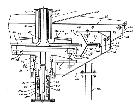
~ s shown in Fig. 1, the upper part of the apparatus is
surrounded by a launder assembly comprising a top cover 66,
outer wall 67 and a base wall 68 defining an outlet region
69, and peripheral and lower walls 70, 71 and 72 defining a
second outlet chamber 73. It will be observed that the
chamber 69 communicates with the region above the flange
42, while the chamber 73 is positioned to receive material
from the nozzles 65. The launder assembly is of course
mounted on the base 20, by means not shown in the drawings.
The operation of the illustrated apparatus is as
follows:
With the outer drive shaft and the components carried
by it including the support and cover 38, the body member
40, the top cover 41 and the flange 42 rotating at a speed
determined by the drive motor 34, water is supplied from
the feed pipe 48 through the supply pipe 46 and via the
':
128~
well 55 and slots 5~, to the region 54. Simultaneously,
the jig feed in the form of slurry of prepared feed
material is fed to the jig via the slurry supply pipe 49
and the jacket 50. Slurry entering the region 51 from the
lower end of the jacket 50 will o:E course be thrown
outwardly by the rotation of the body member 40, assisted
by the ribs 67 of the body member boss 44. Meanwhile
supply water will have filled the region 54.
Prior to the introduction of the slurry and feed
water, ragging of a size and density chosen to suit the
feed material and the fractions to be separated, is
introduced into the region 51. Suitable materials for
ragging include run-of-mill garnet, balls of
aluminium/bronze alloy, and lead glass balls.
Rotation of the machine will place the ragging against
the screen 52, and as the feed material enters the region
51 and is thrown outwardly, it will move upwardly against
the ragging material and the screen. The ragging will tend
to be compacted against the screen 52 by centrifugal
action, analogously with the compaction of the ragging of a
conventional pulsed water gravity jig. As the diaphragm 57
moves upwardly due to the action of the cams 59 with
rotation of the cam drive shaft 29, the water in the
chamber 54 will be pressurised, and this pulsion will
produce dilation of the ragging, again in the manner of a
conventional gravity jig, freeing the heavier particles of
the feed for outward movement relative to the lighter
~2l391~5
--8--
particles, due to the rotation of the machine. On the
return or downward stroke of the diaphragm 57, the pressure
in the chamber 54 will be reduced and the ragging material
will again become closely compacted, in readiness for the
next dilating pulse.
In this way, as in a gravity jig but with an action
which is magnified by the substitution of centripetal
acceleration for that of gravity, the more dense particles
in the feed will penetrate the ragging and the screen 52 to
enter the region 54. These particles will of course
quickly move to the outer wall of the body 40, and thence
downwardly due to the conical shape of this wall, to enter
the cavities 64. The separated material will then migrate
along the side walls of the cavities 64 to the nozzles 65,
and will exit with a proportion of the supply or "hutch"
water, to the heavies outlet chamber 73, while slurry
containing the less dense fraction will fail to penetrate
the ragging and will flow from the region 51 at its open
upper end over the dam ring 43 and thence across the flange
42 to the chamber 69.
~ .s was mentioned above, the side walls of the chambers
64 are contoured so as to present at any point along their
length to the nozzle, a constant angle to a radius from the
axis of rotation of the machine. The choice of this angle
will be influenced by the surface finish and the frictional
properties of the materials involved, but an angle of 30
has been found suitable. The angle is chosen such that no
~289~L5
~9--
accumulation of material will occur along these side walls,
but rather the cavities 64 will continually be scavenged by
rotation of the apparatus at its normal operating speeds.
In the ideal case of a body of fluid of density p
rotating at angular velocity ~ about a vertical z axis
with radial restraint (for example, within a rotating
cylinder), with gravity acting in the direction of the
negative z axis, it can be shown that in steady state
conditions the pressure at a point (r, z) wi~hin the fluid
is given by the expression
P = P + p [ (H ) ~L2 2 2~
where p is the pressure (for example, atmospheric~ at the
free surface of the fluid passing through the point (R,
H). Since at the free surface of the fluid, p = p , then
the free surface is defined by the equation
z = H ~ 2- (R2 - r2)
The point (R, H) in the illustrated jig will ~e set by
the height and internal diameter of the dam ring 43.
In the ideal operation of the illustrated jig the
fluid pressure at the interface of the ragging and the
slurry will be constant throughout the height of the
slurry, and it will be apparent from equation (1) above
that this interface will lie on a paraboloid~of revolution,
as will the free slurry surface defined by equation (1).
In accordance with the invention, the screen 52 is
shaped so that the slurry/ragging interface will lie on the
necessary curve for the particular speed of rotation at
~2~9~5
--10--
which the jig is to operate, using the relationships
outlined above.
In the ideal case, the shaping of the screen provides
a constant thickness of ragging over the height of the
screen. The curvature of the screen is therefore set as
the curvature of the theoretical ragging/slurry interface,
the ragging thickness being set by the quantity of ragging
introduced into the machine.
Thus the theoretically correct curve for the
ragging/slurry interface may be calculated, and this curve
displaced radially outwardly by an amount ~r equal to the
ragging thickness, to define the curve for the screen
contour. Approximations to this curve can of course be
arrived at by other means based on the general
considerations outlined abo~e. In fact, however, the
correct curve for the screen will be a parabola which has
somewhat greater curvature than that which would be derived
from the above approach. This arises from the fact that
incoming slurry will be the subject of hysteresis, leading
to the bottom of the free slurry surface being located
radially inwardly of that which would otherwise be
expected. The most recently introduced particles at the
bottom of the screen will therefore be subjected to less
acceleration than that occuring at the screen itself. As
the particles move upwardly they will move outwardly and
their acceleration will increase.
It will be apparent that as the speed of jig rotation
,
1~:89115
increases, the optimum screen shape will decrease in
curvature, and in the limiting case of infinitely great
acceleration, the optimum screen shape would be a
cylinder. In practice, however, this effect will be
counteracted by the hysteresis efEect described, and with
decreasing acceleration, as the curvature of the
theoretical screen parabola increases, the hysteresis
effect decreases in relative significance, so it will be
found in the practice of the invention that these effects
tend to cancel each other out so that the optimum parabola
will be applicable over a range of jig speeds.
The depth of slurry over the jig bed is determined by
the radius of the dam ring 43, and in this first embodiment
the machine may be equipped with interchangeable top covers
41 having dam rings of differing diameters, to enable
adjustment of the slurry depth to maximise the recovery for
a given feed material.
It should be appreciated that at the very high
accelerations at which a machine of this kind may be
operated, the absolute extent by which the screen 52 will
depart from a simple frusto-conical shape tas taught by
Cross) or indeed a cylinder (as taught by Campbell~ will
appear to be quite small. For example, at 80 G in the
machine illustrated, where the height of the screen is 63
mm the bottom of the screen will lie only 3 mm radially
inwardly of the top. But in this context it must be borne
in mind that the ragging thickness is of the order of 19 mm
. . .
1~9~
-12-
and the slurry thickness typically 5 mm. Furthermore, the
concentrate particle size may be less than 100~ m, and the
ragging diameter in the region of 600-lOOO~m. The screen
shape is therefore of great importance if the efficiency of
operation of such a jig is to be rnaximised.
It will have been observed that the diaphragm 57 is
annular, and operates only in the region radially beyond
the screen 52. This ensures that the diaphragm does not:
operate inwardly of the notionally extended free slurry
surface, that is to say within the region where, were the
chambers 51 and 54 extended downwardly instead of
terminating at the diaphragm and the support housing 25, no
slurry would be present due to the free slurry surface
being radially outwardly spaced from this region.
In this way, by the use of an annular diaphragm
immediately below the level of the bottom of the screen 52,
the diaphragm is located in great proximity to the body of
hutch water in the region 54, thereby minimising the mass
of water to be moved and maximixing the coupling between
the hutch water and the diaphragm. The diaphragm can be of
an area approaching that of the bottom of the volume of
hutch water, minimizing the length of diaphragm stroke
required for a given pulsion effect.
The efficiency of pulsion achieved in the present
invention compared, for example, with that of Cross, is
further enhanced by the fact that the diaphragm is coupled
with fluid substantially all of which is at the high
~2~gl~
-13-
pressure which exists in the region 54 due to the
centrifugal action. This pressure not only assists the
descent of the diaphragm to its lowermost position under
the control of the cam 59, but in fact maintains a net
downwardly directed force on the cam. Thus the compaction
of the ragging on the return stroke is both rapid and
extensive, and there is little net flow of hutch water to
the region 51. In fact, the addition of water to the
tailings should not exceed about 5~.
The effect of this hydraulic behaviour is to produce
both positive and negative pulses in the ragging, an effect
which cannot be achieved by Cross, who does not rotate the
entire body of feed, ragging and hutch water. Neither can
this effect be achieved by Campbell, due to the manner of
pulsion which he employs.
A machine of the type described and illustrated has
been demonstrated to provide extremely efficient separation
of particles according to their specific gravity, and is
particularly efficient in the separation of fine particles
which cannot be handled by conventional separating
equipment, for example particles below 100 ~ m. Equipment
constructed in accordance with the preferred embodiment has
achieved useful separation of particles in a size range of
50% passing 20 ~ and 8% passing 5 ~ , achieving
concentration of greater than 30 times, and useful results
can be expected with gold having particle sizes down to
~ m, and has recovery rates of 90% or better.
.~ '
.
~2~
The speed of rotation of the outer driving shaft 23,
which of course determines the acceleration applied to the
particles, and the speed of rotation of the cam driving
shaft 29 which determines the pulse rate of the jig, will
be determined by experiment for particular materials. It
will be found that operation of the apparatus at speeds
which achieve accelerations in the region of 100 g at the
ragging, will produce satisfactory results. The length of
the stroke of the diaphragm 57 is of course controlled by
the parameters of the cam surfaces 61, and the cams 59 may
be replaced to vary this stroke length in order to optimise
the operation of the machine for a particular feed
material.
Many alternative embodiments of the present invention
are possible, and it will be understood that the embodiment
described and illustrated here is given by way of example
only. The diaphragm 57 may be replaced by diaphragms
located, for example, on the side walls of the machine, and
alternative methods of actuating the diaphragm are
possible, including, for example, electric or
electromagnetic devices. Similarly, the disposition and
arrangement of the feed and or the ragging may take forms
different from those described above.
One such alternative embodiment is illustrated in
Figs. 9 and 10, which show an alternative and more compact
mechanism for oscillating the diaphragm 57.
In this embodiment the cover 38 and pulsator body 58
are replaced by a single support member 74 mounted on the
.. . . ~; ~
- ~2~9~
-15-
flange 24 The mernber 74 is provided with an inner
cylindrical flange 75 which supports the support housing 25
and the inner edge of the diaphragm 57, and an outer
cylindrical flange 76 which supports the outer edge of the
diaphragm 57, and the body member 40.
Mounted on the upper end of the cam drive shaft 29 is
a bevel gear 77, supported on bearings in a housing 78
which is in turn supported on the flange 24.
Also mounted in the housing 78 at equally
circumferentially disposed positions are radially
orientated pinions 79, driving radial shafts 80.
The shafts 80 pass through apertures in the inner
cylindrical flange 75, and the outer end of each shaft is
located in a bearing 81 mounted on the member 74 between
the flanges 75 and 76. Attached to the outer end of each
of the shafts 80 and supported in turn by an outer bearing
8~ is a crank portion 83. The crank 83 in each case drives
a diaphragm engaging member 84.
In the illustrated embodiment, six such eccentric
diaphragm driving assemblies are disposed around the
circumferential extent of the diaphragm 57, and it will be
appreciated that the members 84 will produce vertical
oscillation of the diaphragm in unison, as the cam drive
shaft 29 rotates to ~e drive, in turn, the radial shafts
80.
The individual crank members 83 are readily accessible
through apertures in the outer flange 76, and may be
changed when it is desired to alter the stroke of the
, ' '
- ~L2~91~L5
-16-
diaphragm 57.
A further and different approach to the pulsion of the
hutch water in a centrifugal jig of the kind to which the
present invention applies is illustrated in Figs. 11 and
12, where as before, corresponding reference numerals are
used for those components which correspond to components of
the previously described embodiments.
In the embodiment illustrated in Fig. ll the diaphragm
57 as such is eliminated, allowing great simplification of
the jig from a mechanical point of view. Instead of a
diaphragm, an air/water interface is created in the region
below the hutch region 54, and the pressure of this air is
pulsed to produce the necessary pulsion of the hutch water.
As shown in Fig. 11, the jig of this embodiment
comprises a frame 85 suporting the base 20, with a lower
shaft housing 86 mounted below the bearing housing 21. As
a separate drive i5 no longer required for the diaphragm,
the hydraulic motor 34 is mounted directly beneath the end
of the housing 86.
In Fig. 11, the heavies launder outlet is located at
87, and the light material leaves the machine at 88.
As shown in Fig. 12, the upper housing ~9 which
defines the hutch space is mounted on a lower housing 90
which in this embodiment is shaped substantially as a
mirror image of the housing 89, forming a cavity 91 below
the hutch region 54.
The cavity 91 communicates by means of passages 92
with a central chamber 93 formed between the central boss
, .. . ~
. . ,
llS
44 and the flange 24, and this chamber in turn communicates
with an axial passage 94 in the upper portion 23a of the
jig drive shaft.
Splined to the bottom of the upper drive shaft portion
23a is the lower drive shaft portion 23b, and this is in
turn coupled with the hydraulic motor 34 ~Fig. 11). An
axial passage 95, closed at its lower end and open to the
passage 94 is provided in the shaft portion 23B, and this
passage is provided with one or more radial ports 96
communicating intermittently, as the shaft 23b rotates,
with an air inlet passage 97 in the lower shaft housing
86. A peripheral seal member 98 is located around the
shaft portion 23b within the housing 86.
At the foot of the passage 95 an outlet port or ports
99 communicate intermittently with an outlet 100 in the
housing 86.
The air inlet 97 is connected to a source of
compressed air, so that as the jig rotates, successive
pulses of air pressure are introduced into the chamber
93. The background air pressure is adjusted such that for
the speed of rotation employed the air/water interface at
101 lies somewhat radially beyond the free surface of the
water in the cavity 91, and the pulses of increased
pressure will move this interface outwardly, creating the
required pulsing effect in the ragging at the screen 52.
The depth oE the cavity 91 is preferably such that the
height of the aix/water interface 101 is substantially that
Oe the screen 52, and qui e ~-all exce~s air p-essurA is
~L2~ S
-18-
required to obtain the desired pulsion of the hutch
water. Again in this embodiment, the location of the
pulsing interface provides efficient coupling with the
hutch water, and achieves rapid dilation and compaction of
the ragging.
In the embodiment shown in Figs 11 and 12, slurry is
introduced to the screen area by radial passges 102 in a
distributing member 103 mounted on the boss 44, these
passages, the supply jacket 50 and the boss 44 being
provided with abrasive resistant polyurethane coatings
104. In the heavies outlet chamber 73 a rubber damping
wall 105 is suspended opposite the nozzles 65, to reduce
abrasion within this chamber.
By appropriate relative shaping and location of the
air inlet ~7 and the outlet 100 and the ports 96 and 99,
the magnitude, frequency and shape of the air pressure
pulses acting on the air/water interface may be controlled
and set by experiment to those which are suited to the
speed o rotation of the jig and the nàture of the feed
material.
The outlet 100 not only provides for the momentary
escape of air during pulsion, but also enables water from
the cavity 91 to drain from the jig when the jig becomes
stationary.
Although air is preferred as the gaseous fluid
employed in this form of the invention, where a source of
other gaseous fluid under pressure is conveniently
available, this may of course be employed.
': ~
1~8~ LS
--19--
In a practical jig according to the embodiment of
Figs. 11 and 12, suitable pulse rates have been found to
lie in the range of 1400 pulses per minute to 2500 per
minute or more. As the acceleration at the air/water
interface 101 increases rapidly as air pushes water
outwardly from the parabola of revolution representing the
steady state free water surface, with a corresponding
increase in the return pressure of the water, it is found
that the correct air pressure for a given angular velocity
will be established by gradually increasing the pressure as ~;
the jig is run, until pulsion of the hutch water and
ragging occurs.
Apart from the control which can be obtained by
adjustment of the air inlet and outlet port lining and
shape, the radial contour of the chamber 91 may also be
modified to alter the relationship between the pressured,
as the air/water interface and its radial position, thereby
modifying the pulsion waveform.