Note: Descriptions are shown in the official language in which they were submitted.
~9;~
FIELD OF TH~ INVENTIO~
I~he pcesent invention celates to a process for
dewatering peat and moee particlllarly relates to a continuous
thermo-mechanical process fo~ treating raw peat to remove
thereform significant amounts of water so that the peat may be
mo~e readily transported and utili2ed.
B~CKGROUND OF THE INVENTION
Peat is a carbonaceous resource which occurs very
extensively in Canada and other circumpolar countries. It is
also found in many tropical countries where aperopriate
conditions of high water content and absence of oxygen allow
the accumulation of decaying biomass. ~s a result peat in situ
is often extremely wet and may contain less than 5% by weight
of solid material. In order to transport and utilize peat, it
is necessary to remove the majority of the water as close to
the mining site as eossible. Generally a solids content of
greater than 50% is desired. To put this problem in its most
dramatic pecspective, 18 tonnes of water would have to be
removed from 20 tonnes of such peat as mined in order to
produce 2 tonnes of 50% moisture content peat. The energy
contained in the final eroduct is much less than that required
to remove 18 tonnes of water and as a result it is not
practical to use direct thermal means involving evaporation of
the water to prepare the dry peat.
- 2 -
~;~l39361
Peat as found in nature has undeLgone va~ying stages
of biological decomposition. Peat is formed by microorganisms
f~om plants of lignocellulosic natu~e. Acco~ding to the extent
of the decom~osition it is possible to recognize the natuce of
the lignocellulosics originally eresent. It is thus normal to
find remnants of hemicelluloses, some sugars, cellulose,
lignin, peptides and newly created materials obtained via the
microorganisms~ action. Metals are normally complexed to these
macromolecula~ structures indicating a possible role during the
decomposition.
The structure (three-dimensional) of peat is not yet
known with certainty although the following picture should
aperoximate the actual arrangement:
- a central core of humic materials, highly
hydroaromatic, derived most likely from lignin
and cellulose degradation;
- the core consists of phenolic-like monomers
bridged via O bonds and adopting, for entropy
reasons, a coiled position;
- a very large number of OH gcoups impart their
hyd~oaromatic nature to this core;
- attached to this central core via hydrogen-bonds
are:
carbohydrates, mainly of cellulosic nature
although in some cases the hemicelluloses
might have contributions
1;~8~3~fi~
peptides, contcibuting a significant
percentage to the total N eresent in peat
inorqanic _atter eithe~ entraeped or
ion-exchanged (metals)
re ~ s and waxes derived fLom the plant
liptinitic material and probably absorbed
via some H bonds to the central core
The hydrophilic nature of peat should thus be
attributed to the extraordinary capacity of the material
towards H-bonding.
In well decomposed mateLials the fibrous character of
the cellulose remnants is almost non-existent. The overall
peat structure becomes highly colloidal in an environment
somewhat acidic whose pH varies between 3 and 6, although
noemally it is between 4 and 6.
Peat that has only lightly decomposed still contains
recognizable plant debcis and is often sold as horticultural
peat. The von Post scale is used to describe the extent of
decomeosition and has limits of l and lO. Peats for energy
purposes are generally of von Post values of 5 or greater.
Such peats are very decomposed and have a colloidal structure
which makes it very difficult to simply press the water
mechanically from the peat and water matrix.
-In countries with appropriate climates - long frost
free periods, adequate and predictable periods of
dry/sunny/windy weather - a solar drying method based on
-- 4 --
. .
,
1;~89~
milling or ex~ruding the peat on the prepared surface of the
bog is possible. This is practiced on a large scale in the
USS~. Finland, Sweden and Ireland. The Canadian peat moss
industry uses similar methods but the short seasons can only be
justified for a premium product such as horticultural peat moss.
Whece climates are more severe and there is an
application for peat such as energy which requires almost year
` round operation, thermal treatments have been proposed which
exploit the thermal/mechanical rearrangement of the peat/water
matrix in order to have the bulk of the water drain from the
matrix by, for example, filtration followed by thermal drying.
Processes of thermal rearrangement and mechanical
treatment of peat are known. A semi-commercial plant using
such a process for example was in operation around the end of
World War I in Dumfries, Scotland.
More recent processes include derived fuel processes
(PDF) and the Koppelman process.
The PDF process is a wet carbonization treatment of
peat at 200C, 2.5 MPa and residence times of 30 minutes.
Specially designed heat exchangers and multiple-effect
condensor-evaporators are used for efficient hea~ recovery to
pcovide a thermal efficiency estimated between 72% and 80~.
The wet carbonized peat slurry is dewatered to 50 weight
percent moisture in semi-continuous and fully automatic
pressure filters. The fil~er cake is then pulverized and
further dried to about 10 weight percent mois~ure in a flash
dryer. The dried peat is then pelleted and briquetted.
~89~6~
The Koppelman peocess, described and illustrated in
U.S. Patent No. ~,477,527 issued October 16, l9B4. is a
two-stage, high temeerature, high pressure beneficiation
erocess giving a K-fuel product with a heating value about 50%
greater than that of the raw peat. The first stage is a wet
carbonization under conditions similar to the PDF process
followed by filtration to 70 weight eercent moisture. The
dewatered peat is conveyed by a twin-screw feeder to the second
stage operating at 400C and 10.4 MPa for a residence time of
10 minutes. The eeat is extruded and cooled giving a K-fuel
product with less than 10 weight eercent moisture.
A useful criterion for assessing the utility and
e~acticality of such erocesses is a measurement of the
"severity" of the process. The parameter that reflects
severity of such a process is a "P" factor which is calculated
as follows:
P = duration of treatment x exp (TreaCtion
( 14.75)
Where T reaction is the ceaction temperature of the peat.
The severity of a typical PDF process and a tyeical
Koepelman erocess is set out in Table I hereafter.
TABLE I
ProcessTeme/C Time Mass Heating "P Factor"
Min. Yield % Ratio* min
PDF210 30 60 1.21 52000
Koepelman 320 15 40 1.22 4S0000
-- 6
1~9~61
* ~he heating Latio i8 the ratio of the highe~ heats
o~ combustion of the product ove~ those of the input
peat.
It can be seen from the above Table that the existing
P~F and Koppelman processes use long duration treatments and
obtain a dewaterable product in reduced yield due to theic high
severity. This causes solubilization of a laLge amount of the
peat and this in turn is costly with respect to the water
treatment. The long duLation treatment results in low
throughput per unit of investment.
Othec plocesses of dewatering peat, eithe~ being wet
carbonaceous processes or erocesses using heat and high-
pressuLe in combination, are described and illustrated in U.S.
Patent No. 2,573,134 of Gebau~er issued Octobe~ 30, 1951, U.S.
Patent No. 2,668,099 of Cederquist issued February 2, 1954,
U.S. Patent No. 4,153,420 of Myreen issued May 8, 1979
(co~responding to Canadian Patent No. 1,119,407 issued Ma~ch 9,
1982) and Canadian Patents Nos. 188,789 of ten Bosch issued
F~ebruary 18, 1919 and 208,415 of ten Bosch issued February 8,
1921. ~gain, such processes use long duration treatments and
- have high sevecity.
Finally, a recently developed Russian hydrolyze~
pcocess has been used in the e~oduction of sugars (apparently
fecmented to single cell p~otein). This process is not
intended for dewatering of peat. This plocess, developed at
the Institute of Wood Chemistry in Riga, is intended to process
~;~8936~
peat (slightly decomposed i.e. von Post l-Z humification) &O
that a fermentable juice for the production of a single cell
protein is obtained. That process involves:
- milling peat.
- drying eeat in an oven.
- mixing d~ied material with concenteated sulphueic
acid in a proportion eanging from 1.5 to 3 g
H2SO4/100 g of dry peat.
- the mixed material is then extruded thcough a
screw-ty~e ceactor where intensive shear forces
break down the polymeric structures causing
substantial hydrolysis.
- the mass then enters a reactor where it is
diluted with H20 and steam is added to heat the
slurry thus formed. The slurry must thus be
heated to about 140C - lgOC where
solubilization of the sheared polymers and its
final hydeolysis to monomees is conducted.
A disadvantage of the Russian technology is that it
cequiees drying the initial peat which makes it unsuitable as a
dewateeing peocess.
Modification of the Russian technology to process wet
highly decomposed mateeial seems improbable since, once
maceeated, the wet material acts as a fluid not peemitting any
extrusion.
~9~6~
F~om the Russian experience, however, it i8 realized
that extensive hydrolysis is possible and relatively easy to
ca L Ly out.
OBJECTS OF THE INVENTION
It is an object of the present invention to provide a
novel peat dewatering process having low severity for use in
conjunction with the wet mixing of peat. It is a further
object of the present invention to provide such a erocess which
will eroduce, from even ext~emely wet raw peat, a eeat product
that can be easily dewatered in a filter press of values to 50~
to 60% water content using relatively low thermai energy and
with relatively minimal solubilization of solids.
SUMMARY OF THE INVENTION
In accordance with the present invention there is
erovided a process for dewatering peat comprising the stees of:
(a) flowing a slurry of macerated peat through a
reactor directly heated by the addition of live
steam,
(b) subjecting the heated mass in the reactor to
intense mechanical shear and
(c) quenching the product from the reactor.
3936~
In a prefec~ed embodiment of the invention, the slurry
in the reacto~ is heated to a temperature in the ~ange of ahout
160C to 200C and is subjected to mechanical shear and post
hydrolysis for a time of between about l to ~ minutes. The
mechanical shear is pLeferably achieved by passing the peat
slurry thcough na~ow orifices in a nozzle means in the
reactor, the size of the o~ifices being such that flow profiles
will be developed in the slurry to break apart the stretched
polymers of the peat and thereby facilitate the hydrolytic
pcocess.
It has been found that the process according to the
present invention produces conditions of low severi~y as
defined by the "P Factor~ of values less than l,000. ~s well,
the product produced according to the process of the present
invention can be easily dewatered in a filter press to values
of 50% to 60% water content.
BRIEF DESCRIPTION OF THE DRAWINGS
These and other objects and advantages of the
invention will become apparent upon reading the following
detailed description and upon referring to the drawings in
which:
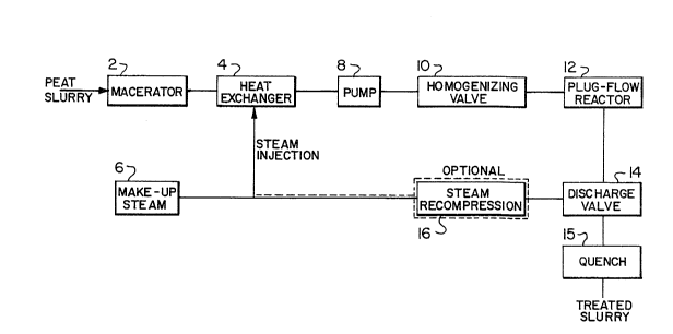
FIGURE l is a schematic flow chart of the process
according to the present invention;
- 10
.
1~39.~fi~
FIGU~E 2 is a moLe detailed schematic flow chaLt,
illustLating typical ope~ating conditions, of the process of
FIGURE 1: and
FIGU~E 3 is a schematic diagram illustrating in
5greater detail the components of the reactor of the present
invention.
While the invention will be described in conjunction
with example embodiments, it will be understood that it is not
intended to limit the invention to such embodiments. On the
10contrary, it is intended to cover all alternatives,
modifications and equivalents as may be included within the
spirit and scope of the invention as defined by the appended
claims.
DET~ILED D SCRIPTION OF THE IWVENTION
15In the following description, similar features in the
drawings have been given similar reference numerals.
Turning to FIGURE 1 there is illustrated a schematic
flow sheet of the low severity peat dewatering process in
accordance with the invention. In the pLocess, raw eeat, which
20peat may for example contain less than 5~ solids (but which is
more nocmally concentrated to about 10% - 15~ solids using
classical mixer/settle~ technology), is macerated and made into
a slurcy at macerator 2. The slurry is passed through a heat
exchanger 4 where steam from a source 6 is injected to
-- 11 --
... .
~;~89~6~
app~opriately heat the slurry, e.g. to 160C to 240C, and
preferably 160C to Z00~. The heated slu~Ly is then pumped by
means of pump ~ through an homogenizing valve 10 wheLe it is
subjected to intense mixing mechanical shear and then passed
along a plug flow ~eacto~ 12. The peat product f~om the
eeactor lZ is then passed through discharge valve 14 into a
quench bath 15 and recovered f OL subsequent treatment, such as
centrifuging and eressing to produce pea~ of a desired moisture
content (e.g. 50% to 60%). The time for the slurry in passing
through homogenizing valve 10 until it is quenched, may be from
about 1 to 3 minutes. Steam flashed during the quench process
may optionally be recovered and compressed at 16, and used as
steam for injection to heat exchanger 4.
An example installation for carrying out the process
of the present invention is depicted schematically in FIGURE
2. Raw eeat, to be macerated, is passed from reservoir 20
through a Seepex (trade mark) macerator 24 into reservoir 26.
As required, macerated peat slurry held in reservoir 26 is
passed by means of pump 28 to reservoir 30 and then, by means
of high pressure Seepex (trade mark) pump 36, to the
homogenizing valves 42 and 46. ~ linear flow rate of peat
suseension through the system of 0.1 to 0.4 cm~s has been found
to be suitable.
During maceration~ proper screening of stones and hard
granular material is re~uired. In this regard macerated peat
suspensions may be screened, for example through a 2 mm screen
- 12 -
~, .
~ ~39~63L
opening E)rior ~o entering the pumps. Prior to maceration, the
peat may be screened to remove stone and debris which could
damage the macerator itself.
The continuous processing of the peat suspension is
conducted as follows:
- the peat from macerator 24 is passed to reservoir
30:
- high-eLessure Seepex (trade mark) pump 36 feeds
recirculating pump 38 (e.g. 10 litres eer minute)
which also aspires some of the material
accumulated in reservoir 40;
- while the recirculation takes place around pump
38, a first "cold" homogenizing treatment (e.g.
less than 100C) takes ~lace with valve 42
(typically eressure differentials of 4.1 to 5.5
MPa aLe used for this stage);
- a fraction of the peat suseension (1 litre~min
aeproximately) is sent to pump 44 via a
mixer~heat exchanger 43 where steam is injected
to raise the temperature of the peat suspension
to the desired level;
- a second homogenizing treatment can take place
through valve 46 at the pre-established
temeerature level (e.g. at a temperature in the
range of about 160C to 240C). A eressure
differential of about 24.8 MPa is maintained
through valve 46 when in use;
- 13 -
36~
- a tubular reactor 4B of varying length completes
the treatment at the pre-established temperature
level before quenching. The length i6 chosen to
give the appropriate level of severity as defined
by the P factor, e.g. at 190C and an 88 sec.
residence time in reactor 48, the P factor is 655;
- flashing and discharge takes place at quench
receivet 50, where the peat suspension is then
passed, bringing its temperature down to about
100C or less; and
- steam condensation, if wanted, is conducted at
vessel 51.
The solids concentration of the peat suspensions processed
using such a system varied between 12.3% and 13.7% by wt
For homogenizing valve 46 to be used in accordance
with the present invention to create high shear on the peat,
any standard type homogenizing valve for example as used in the
dairy industry may be used. Such valves for instance are made
by A.P.V. Gaulin.
In addition, in FIGURE 2, water pump 52 is used to
bring the system to the desired temperature, and acid injection
~ump 54 and base injection pump 56 are included for use, if
needed (although it has been found in experiments conducted
using apparatus in accordance with FIGURE 2 that no acid or
base addition to the peat was required).
- 14 -
1~8~6~
Steam is p~oduced at boile~ 58 for heat exchangec 43
and watec is pumped by pump 60 to boiler 58 as requiced.
rrhe peat product fcom quench ceceiver 50 may then be
subsequently pcocessed. for example by centcifuging and/or
pressing.
Tucning to FIGURE 3 thece is illustrated a flow sheet
illustcating typical operating conditions foc an example
embodiment of the peat dewatecing pcocess of the ~cesent
invention. Pcessuce and temperature conditions at the vacious
stages of the pcocess ace illustrated. In the embodimen~
illustcated in FICURE 3, the tceatment consists of steam
injection followed by oxygen injection into mixecs 64 and 65
prior to passage through an homogenizing valve 46 and followed
by quenching at 50. ~n alternative approach would be to use
steam only and a temperatuce of around 190C to 210C.
The quenching step in the pcesent invention is
extremely impoctant because. by bringing the temperature
capidly from the 160C to 240C range to 100C or lower, this
quickly terminates the hydrolytic and other reactions which
have been taking place in the peat suspension from the time it
has passed through the homogenizing valve. This pe~mits better
control of these reactions, to maximize solids content
recoverable after quenching.
It should be noted that the low sevecity of the
process in accocdance with the present invention is derived
from the relatively shoct ceaction time between passage of the
-- 15 --
1~893~
eeat slurry through the homogenizing valve 10 (FIGURE 1~ until
it is quenched. This time may be as little as 2 minutes and
the quench time itsel~ may be less than 1 second. Preferably
the peat slurry is quenched after th slurry has accumulated a
total P factor, P of between 500 and 1500 minutes.
Until the quenching steL~, it is important in carrying
out the process of the present invention to ensure that the
~ressure a~ any point of the process is greater than that for
saturated steam at the temperature of that point.
EXAMPLE
Peat from the FaLnham Bog (Quebec, Canada) was made
into a peat slurry by mixing the peat as received with water in
order to obtain an 13.5% solid concentration. The process
configuration was that of FIGURE 2. The mixing was ensured by
macerating with a Seepex (trade mark) macerator 24 (of FIGURE
2) in the loop described by macerator 24, reservoir 26, Seepex
pump 28 and back to vessel 20. The pre-macerated slurry was
then utilized by pumping it at a rate of about lkg/min. of
slurry to the reactor loop 36, 40, 30 for a cold homogenization
prior to introduction to the mixer/heat exchanger 43.
The final quenched material was filtered in a small
scale press to solids concentration of 44% - 48%. ~liquots of
the treateA slurry were also subjected to assessment in the
labocatory as described below.
- 16 -
The the~mally treated slurry was filtered in a Buchner
filter kit using a Whatman (trade mark) ~40 filter paper. One
20 gr-aliquot of the wet pressal,e was used to determine the
extent of dewa~ering reached.
This 20 gr-aliquot was introduced in a press
consisting of a 50 mm-diameter pis~on. After having applied a
500 esig load ~3.45 MPa) on the piston, the residual pressure
was recorded after 1 minute and immediately readjusted at the
500 psig load. This procedure was repeatedly done until no
further changes in pressure were detected.
Ultimate analyses of the air-dried residues were made
to determine the extent of the severity of the treatment.
These analyses were performed used an elemental analyzer
(Perkin Elmer, model 240C). Table II sets out results obtained
using this system at varying temperatures of peat slurry in the
primaLy receiver.
TABLE II
Process Temp/C Time Mass Heating "P Factor" Solids
Min. Yield % Ratio~ min Content
%
UdS/NRC 175 1.47 81 1.07 237 42.7
190 1.47 72 1.10656 46.4
210 1.47 72 1.10Z541 48.Z
- 17 -
~9~fi~
The heating ratio is as defined above in Table I but
in this instant is estimated from the change in
elemental composition.
The pcoduct peat from these experiments was pressed to
a moisture content 50% - 6U%, a level very suitable
for thermal dcying.
In repeated processing of peat slurry according to the
above method at different temperatures, a recovery of more than
85% of the initial solids was achieved at temperatures below
180C. For temperatures between 18~C and 235C, the
cecoveries dLopped to c.a. 60%. Beyond 235C, it was merely
50%.
Fco~ the above-noted tests, it has been determined
that the reduction of water content in peat is Leadily achieved
down to about 5~% by simple macecation followed by passage
through the homogenizing valve, quenching and eressing. The
impoctant effect of that treatment is to shorten pressing time.
Thus it is apparent that thece has been provided in
accordance ~ith the invention a process for dewatering peat
that fully satisfies the objects, aims and advantages set forth
above. While the invention has been desceibed in conjunction
with specific embodiments theceof, it is evident that many
alternatives, modifications and variations will be apparent to
those skilled in the art in light of the foregoing
descrietion. ~ccordingly, it is intended to embrace all such
alternatives, modifications and variations as fall within the
sei~it and broad scope of the invention.
- lB -
'
,
,