Note: Descriptions are shown in the official language in which they were submitted.
- ~28~
Title:
Means for securing objects
Technical field:
S The present invention relates to a means for securing
objects comprising a locking arm pivotally mounted ;n a frame
which is so arranged, with the means in a securing position, as
to be forced against a surface of the frame with the object lying
in between and as to be swung from the securing position into a
released position.
Background:
For the Durpose of securing objects, for example pieces of
material, in such a way that the object can be released
easily, a number of different solutions is available
depending on the desired function and the type of the
object. PreviousLy discLosed for the purpose of securing pieces
of materiaL, for example, is a means in the form of a
spring-loaded arm which secures an object by friction against a
holder positioned in front of it. By moving the arm out of the
way in an upward sense the piece of materiaL can be removed
from its secured position. Having to swing the arm
upwards constitutes a movement in an unfavourable sense, because
it takes pLace in the opposite direction to the desired movement
required to release the object, whereas to overcome the friction
by puLling in a downward sense can cause damage to delicate
pieces of material in certain circumstances.
Technical problem
The object of the present invention is to eliminate the
aforementioned disadvantages by means of a securing means which
operates in a highly favourable manner for the object.
.~
~897~3
, . ..
The solution:
The aforementione~ object is achieved by the medns in
accordance with the invention, which is characterized in ~hat
said surface forms a limit stop for the !ocking arm so arranged
as to restrict the pivotaL motion of the locking arm in one
direction of pivoting, and in that the means incorporates devices
for rearranging the ~ocking arm in such a way that it is abLe to
swing past the limit stop ir,to a released position.
Brief description of drawings:
The invention is described below in more detail in relation
to a number of typical embodiments with reference to the
accompanying drawings, of which Fig. 1 shows a longitudiraL
section through the means in accordance with the inventicn in a
first embodiment~ Fig. 2 shows part of the means in accordance
with Fig. 1 in a different position, Fig. 3 shows a partly
sectioned view from the front of the means in accordance with
Fig~ 1, Fig. 4 shows on a larger scale a part of the means in
accordance with the invention, Fig. 5 shows a longitudinal
section through the means in a second embodiment in a first
position, ~hilst Fig. 6 shows the means in a second position,
Figs. 7, 8 and 9 show parts represented entirely schematically in
three different positions, and Figs. 10, 11 and 12 show the means
in a third embodiment.
Best mode of carrying out the invention
The means in accordance with the examples shown has been
produced especiaLly in order to permit the efficient handling of
p;eces of text;le material in the clothing industry. The
suspension means in the example shown is intended to constitute
or form part of a transport unit in an overhead conveyor system
for the transport of pieces of textile material between different
work stations, in which case it is important to be able to
release the pieces of cloth effectively from the suspension means
without the risk of damage to the textile material.
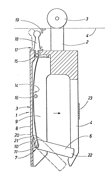
As may be seen from Fig. 1, a section is shown through a
- ~''8~ 3
suspension means in accordance with the inYention in the form of
a first embodiment suspended by means of a bracket 2 from a
conveyor roller 3, by means of which the suspension mPans moYes
along a conveyor 4 represented schematically. The movem~nt ma~ be
achieved, for example, by giving the conveyor a certain fall 80
that the zuspension means will move of it~ own accord The
suspension means consists of a frame 2 with a rsar frame leg 3
and two front frame legs 4, 5, one of which is cut away in Fig.
1. The construction of the front two frame legs is apparent from
Fig. 3, however. A central part of the suspension mean is formed
by a locking arm 6 which is pivotally mounted in a supporting
means 7 in the rear frame leg 3, whilst the securing and locking
of the object which is to be secured takes place against the
front two frame legs 4, 5 which in this case form a holder
against the locking arm. The rear frame leg in the example shown
exhibits a U-shaped section with a back piece 8 and two side
pieces 9, of which one is cut away in the Figures. Between the
two side pieces 9 there is formed a space into which the locking
arm extends by its rear end 10, in which case the arm exhibits a
shaft 11 passing through or two coaxial pins projecting in
opposed directions. The pivot projects into a slot 12 special1y
provided for that purpose in each of the side pieces 9. The shape
of the slot is best appreciated from Fig. 4. The special shape of
~5 the slot provides two stable supporting points for the locking
arm 6, namely a front supporting point in which the arm is shown
to be located in accordance with the solid line in Figs. 1 and 2,
and a rear supporting point in which the arm is shown to be
located in accordance with the dot-and-dash line in Figs. 1 and
2. The slot is shown to be of rather different shape in Fig. 2,
although i~ provides the same function as the slot in accordance
with Figs. 1 and 4.
The means also exhibits in the typical embodiment shown a
spring mechanism 14 in the form of a wire spring, which at the
bottom is hooked around the shaft 11 and is held between an upper
pin 15 and a fixed, interjacent pin 16 which projects from one of
the side pieces 3, whereby the spring mechanism 14 endeavours to
~89~ 3
retain the locking arm 6 with the shaft 11 ;n ~osi~ion at bo~h
its pi~oting or support points. The spring mechanism 14 also
forms part of a release mechanism 17 which also irlc~rporates a
control lever 18, upon actuation of which the spring mechanism is
caused to rise by the fact that the pin 15 i5 attac~,ed to the
lower end of the lever. By moving the lever to the position
indicated by a dot-and-dash line in Fig~ 1, the mechanism is
caused to rise w;th the result that the locking arm 6 w;th its
shaft 11 is lifted from its front pivot;ng point in an upward
sense and is caused to move backwards to the rear pivoting point
under the effect of the rearward-acting spring bias from the
spring mechanism. The control lever 18 can either be operated
manually or automatically, for example by means of a
downward-projecting and preferably flexible activating element 19
situated at a work station, for example, with the result that the
p;ece of material can be released automatically to fall at the
desired point.
The locking arm 6 also exhibits at its rear end 10 a cam 20
so arranged as to interact with a control surface 21 on the back
20 piece 8 causing the locking arm 6 to move forwards from the rear
p;voting point to the front pivoting po;nt when the locking arm 6
is moved in a direction from the bottom upwards with its front
end 22, for instance between the positions illustrated in Fig. 1.
As ~;ll be apprec;ated from the Figures, the front end of
25 the locking arm 6 projects for a certain distance between the
front two frame legs 4, 5 ~h;ch are made from an elastic
mater;al. The flexibility of the frame legs 4,5 can thus be
regulated by means of a bridg;ng element 23 ~hich is capable of
be;ng displaced up or down the two frame legs. In its upper
position the frame legs are permitted to flex to a great extent,
enabling the front end of the (ocking arm to be pushed bet~een
the thickened free ends 24, 25 of the two frame legs and beyond
them, this being represented schematically by means of
dot-and-dash lines 26 in Fig. 3. In a lower position with the
eLement 23 pushed down to~ards the free ends 24, 25 the two frame
legs 4, 5 are rigid to all ;ntents and purposes and are even
~ 897~
capable of entirely bLocking the passage of the locking arm 6
between the two legs. The length of the locking arm 6 is sucn,
however, that said bLocking will not occur with the lockir,g arm
in its rear position, that is to sar with the shaft 11 positioned
at the rear pivoting point.
The use of the means in accc,rdance with the invention in its
f;rst embodiment is explained with reference to Figs. 1-4. It is
assumed for this purpose that the movable eLement 23 adopts a
position, for instance the position shown in Figs. 1 and 3, which
affords flexibility to the front legs 4,5~ The initiaL position
can be either with the locking arm 6 at its front pivoting point
or with the locking arm at its rear pivoting pc,int. We have
assumed here that the Locking arm is at its position indicated by
dot-and-dash lines in accordance with Fig. 1, and with the shaf.
11 at its rear pivoting point. The securing means is then in its
released position. A piece of textile material is inserted y
holding the piece of material by its upper edge with one hand and
by moving the piece of material upwards in the gap between the
rear and front frame legs 3, 4, S, and then with the same hand
ZO moving the locking arm 6 upwards by causing it to pivot in an
upward sense. The locking arm w;ll then be in a rear position in
which the locking arm is essentially free to move past the two
front frame legs 4, 5 without being obstructed by them, in which
case the piece of material will be situated between the free end
2Z of the arm 6 and the legs. As the arm is swung upwards, the
cam 2 on the arm will engage with the control surface 21, causing
the shaft 11 to move forwards in the slot 12~ and as a certain
angle of pivoting is passed by the arm 6, for instance the angle
shown in Fig. 2, the shaft 11 will be moved downwards and into
3û its front supporting point resting against the supporting
surface 13. Once the front supporting point has been adopted,
the locking arm will have reached the pivoting position shown by
solid l;nes in Fig. 2. If the locking arm 6 is now permitted to
swing back into essent;ally the position indicated by solid lines
in Fig. 1, the arm will be blocked against the front frame legs
4, 5 with the piece of material in between. The fact that the arm
~89~
projects slightly between the frame legs will cause the piece of
material to be ~olded slightly into the shaoe of a 'U', causing
;t to be held securely. ~he means ;n this case will be in the
securing position, enabling the piece of material to be carried
along the con~eyor for the purpose of moving it to another work
station. When it is wished to remove the piece of material, this
can be done in two different ways. The simplest way of achieving
this is to pull the piece of material in a downward sense, when
the locking arm will be allowed to move past the two frame arms
4, 5 which will flex out of the way to a certain extent so that
the locking arm can swir,g down into the position shown in Fig. 1
by means of dot-and-dash lines. The locking arm 6 is thus so
arranged as to be released by being swung c!o~n at the same time
as a force acting upon the arm is overccme, said force being
condsiderably greater than the force required to swing the arm
upwards. When a new piece of materiaL is to be inserted, the
locking arm can be returned by the application of light pressure
to the outer end 22 of the locking arm, causing the locking arm
to move to its rear position at the rear pivoting point.
Alternatively, it is possible for the piece of material, as
described abo~e, to be released automatically or manually by
activating the lever 18, causing the locking arm 6 to move to its
rear pivoting point so that the piece of material is released.
The embodiment in accordance with Figs. 5 and 6 in principle
exhibits the same function with regard to the action of the
locking arm. In this second embodiment, the components which are
~he same as those in the first embodiment have been allocated
corresponding reference designations, but with the addition of
100. In th;s case the mechanism for holding the locking arm 106
about its front pivoting point ;s executed differently. In this
embodiment the slot 112 is executed as a straight slot, to which
has been added a long activating rod128 ~hich e~tends into the
rear frame leg between the upper attachment 115 of the spring
mechanism 114 and the rear end of the locking arm 106. The
activating rod 128 is capable of being moved between an upper
position as shown in Fig. 5 and a lower position as sho~n in Fig.
, ,~, . , ,, .. , . ~, , .
6 in a fashion described in greater detail below. The preD3red
section shown in F;gs. 5 and 6 ;s considered to extend centrally,
from which it will be apparent that the activating rod 728 is
divided at the bottom into two shanks 129 extending along the
inside of the two side pieces 109, said shanks being intended to
;nteract uith the pins 111 of the locking arm 106 in such a way
that, with the activating rod 128 in its lower position ;n
accordance with Fig. 6, the locking arm 106 is held in its front
pivoting position by interaction between the ~ront edges 13D and
said shanks and the pins. The locking arm 106 is also executed at
its rear end with a normal upward-facing finger 131 which can be
introduced into the space between the two shanks 129, in this ~ay
not interfering with them and yet assuring the position of the
locking arm for the purpose of its movement from its rear
pivoting point to its front pivoting point through interaction
with the wall 132 of the back piece 108 as it is swung from the
downuard, released position and in an upward sense. A normal,
backward~facing finger 133 serves the function of moving the
activating rod 128 from its lower position to its upper position
whilst the locking arm 196 is being swung downwards. This may be
appreciated from the schematic views in Figs. 7, 8 and 9, which
show a section made alongside the central section shown in Figs.
5 and 6, and more precisely through one of the shanks 129, in
connection with which the upward-fasing finger 131 does not lie
in the section and is not illustrated in the interests of
clarity.
With further reference to Figs. 5 and 6 it is evident that
the locking arm 106 is also in two parts and is articulated at an
articulation point 134, ~hereby in certain circumstances it is
possible for the arm to be swung upwards ~ithout being moved from
the front pivoting point to the rear pivoting point. In this case
the locking arm 196 is best made from a high-grade elastic
material such that the inherent el2st;city of the material can be
utilized to provicde said articulated function.
The use of the means ;n accordance with the second
embod;ment is explained with reference to Figs. 5~9. The initial
.. , . . _ , . , , . .. . ~, . .
~897;33
.
position ;s such that a piece of material 135, shown in sec~ion
in fig. 6, is held securely between the free outer end 122 of the
locking arm 106 and the two front legs 104.
The activating rod is thus in its
lower position, when its shanks 129 prevent the pins 111 fro~
being displaced from their front pivoting point under the effect
of the spring mechanism 114, thereby causing the piece of
material to be held securely in the manner described above. The
interaction between the activating rod 1Z8 and the pins may also
be appreciated from Fig. 9. By pulling the piece of material 135
in a do~nward sense, the locking arm 1Z6 will be caused to
accompany it because of the friction between the free end 1Z2 of
the ~ock;ng arm and the piece of material, in which case the
back~ard-facing finger 133 will be caused by being forced against
the underside 136 of the activating rod 128 to lift the lat~er in
such a way that the lower edges of the shanks adopt a position
above the pins 111, in which case the locking arm will be caused
to move under the effect of the spring mechanism 114 to its rear
pivoting position in accordance with Figs. 5 and 7 by the
movement of the pins 111 along the straight slot 112.
When another piece of mater;al is to be inserted, the
locking arm is moved in an upward sense with the result that, as
shown by Fig. 5, the upward-facing finger 136 will, through its
contact with the wall 132, cause the pins of the locking arm to
move forwards until the activating rod 128 drops down through ~he
effect of the spring mechanism 114, which is pre-tensioned
against a support point 136 in such a way that a downuard-acting
force is applied to the activating rod.
By analogy with the alternative possibility in the first
3û embodiment, manual or automatic release can be provided by means
of the control lever 118, the actuation of which will cause the
activating rod 128 to be raised and the corresponding events to
occur, as described above.
ln Figs. 10, 11 and 12 there is shown a third embodiment
~hirh differs in certain respects from the preceding embodiment.
The corresponding parts have been allocated the same reference
~f~ 3.3
designations, but ~ith the addition of 200. In accordance witr,
this example, too, the central part of the securing means
consists of a locking arm 206 which bridges a gap between a rear
frame leg Z03 and, in th;s case, only a ~ingle front ~rame leg
5 204. The locking arm 206 in this case is best made from an
eLastic material and is div;ded into two parts uhich are
articulated relat;ve to one another about an art;culation point
234. In place of t~o frame legs which are sprung relative to one
another, the front frame leg 204 in this case exhibits a stop 237
which normally forms a limit stop against which the piece of
material 235 is held. The articulation of the locking arm 206 is
such that articulat;on is provided until a certain angle is
reached between the two arti~ulated parts without great
resistance, although further articuLation can only Gccur if an
increased force effect is overcome.
The piece of material 235 is thus held under the eff2ct of
friction bet~een the locking arm and the piece of material, in
~hich case it is possible to reLease the piece of mate-rial by
pulling the piece of material in a downward sense, causing the
locking arm to be allo~ed to pass the limit stop 237 because of
elastic deformation, in conjunction with ~hich the bridged gap
~ill open, when the position indicated in Fig. 12 by dot-and-dash
Lines ~ill be adopted. Alternatively, the release may be
facilitated by manually pressing against the articulation point
234 from below, uhen the locking arm 206 ~ill adopt the position
indicated in Fig. 12 by a solid line.
The return of the locking arm 206 to a position above the
limit stop 237 takes PLace uith minimal resistance due to the
f~ct that the locking arm, as i~ makes sontact ~ith the limit
stop, is able very easily to bend around the articulation point
234 SD that the locking arm ~iLl move past the limit stop ~;thout
problem, ~hen a piese of mater;al can be inserted and held
betueen the lock;ng arm and the frame leg 204.
The invention i~ not restricted to the typical
embodiments described above and illustrated in the dra~ings9 but
may be modified ~ithin the scope of the ~ollowing claims.
397;~;~
For example, the means in actordance with F;gs. 5 and 6 need not
be provided with the articulated function which divides the
locking arm into two parts articuLated relative to each other.
Furthermore, neither the first nor the second embodiment need
necessariLy exhibit the separate release mechanism with the lever
18. Nor need the stop be in the form of two frame legs, as in
the first and second embodiments, bu~ may consist of a ricdge as
shown in the third embodiment, which can thus also be combined
with the return movement of the locking arm by the adoption of
two different pivoting points.
Z5
, . , ._ , ,