Note: Descriptions are shown in the official language in which they were submitted.
SAFE EQUIPPED WITH A PE~UTATION LOCK WHOSE LOCKI~JG
FUNCTION IS RELEASED BY THE INSERTION OF A COIN OR COINS
The invention relates to the design of a safe
having a door which can be locked by means of a per-
mutation lock.
Safes are known whose door bolts are op~rated
by means of a key-activated lock. Such safes are dis-
advantageous when they are used by a number of different
persons (e.g. in hotels, swimming pools, sport facilities~
because in each case it is necessary to pass on the key
to the next user. Handing on the ~ey always involves the
risk that the previous user may have made himself a copy
of the key.
On the other hand, it is advantageous when a
safe which is to be used by a number of diffexent
people is equipped with a permutation lock because,
compared with key-activated locks, it is not necessary
to hand on the key to the next user. It is however
disadvantageous that anybody can use the safe free of
charge because he does not require to pick up a key for
which he must pay a rental fee.
It is a known feature of permutation locXs
that their key code can be adjusted from inside (e.g.
the combination on a permutation lock fitted to a
brief case can be reset from inside the brief case).
This is disadvantageous in the case of safes which are
constantly being used by different people because onse
the safe has been closed the newly set key code is no
longer accessible for the user to note it down, for
example, before the combination is manually scrambled
it would make very little sense to use such locks for
example on hotel safes because guests would be frequently
reporting to the recep~ion desk asking for assistance
~8~7~i
in opening the safes because they had for~otten the
key code which. they had set~
It is therefore the object of the inYention
to create a safe of the type mentioned at the beginning
which. is suitable for use by a constantly changin~ series
of users, yet which at the same time canno-t be opened by un-
authorized persons, and which also permits a rental fee
- to be collected.
In the s~fe accordiny to the invention this
problem is solved by using a permutation lock equipped
with a device for resetting the combination from outside
and also equipped with a coin-operated xelease mechanism~
Combining the perm~ation lock wit.h a coin-operated
release mechanism means that the safe can only ~e used
by the person who, at the start of the rental period,
activated the permutation lock in such a way by inserting
a coin or coins that the lock can be operated to lock
the door. Thus, by eliminating the weak point of key
operated locks, namely the need to hand on a key, as is
the case for example with lockers, the invention shows
one way of providing a safe storage receptacle which can
be used by a series of different persons, while at the
same time necessitating the payment of the user fee. In
addition, the externally operatable combination res~tting
device used on the permutation lock also permits the
selected combination to be read once the sa~e door has
been closed; the combination itself is scrambled once
it has been remembered or noted down. Thus it is a
simple matter to read the combination even after the
safe door has been closed, thus eliminating what fre-
quently happens in real life situations namely that the
user does not realize until after he has closed the door
that he should have noted the combination, as happ~ns
with the known combination resetting devices accessible
1~8~
from inside (e.g. as in brief cases). Such, a de~Jice
could not be used in a sa.e according to th,e invention
because once the permutation lock. is activated the coin
inserted into the key-activated release mechanis~ falls
i.nto the collection container and opening th.e safe again
to determine the combination would inyolve relocking it,
which in turn would require payment of a further rental
fee. The inv~ntion thus demonstrates a novel way in
which - in contrast to the current state of the art -
an externally operatable combination resetting deviceon a permutation lock is coupled with a coin operated
release mechanism.
In a further refinement of the invention the
permutation lock is desiyned to store its combination
once the bolt is activated to close the doorO Th.is is
a fundamentally different feature from that found on
known permutation locks which store their combinations
by the user activating a separate button. In the
object which is the subject of this patent application
the combination is stored by the action of s~tting the
permutation lock in the locked position. Thus, the
combination set when closing the lock corresponds to the
combination which has to be redialed in order to open
the safe~
In a further refinement of the invention,
- the safe can be designed in such a way that the stored
combination can be read off once a securely attached
panel which is accessible from the outside h.as been re-
moved. If the user of the safe forgets the combination,
removal of this panel, which can only be done by
authorized personnel, permits the combination to be read.
In this way, the safe can be opened by calling on the
assistance of an authorized person (e.g~ hotel detective).
This guarantees uninterrupted availability of the safes
7~
~ 4 --
to the various us~rs.
The panel is preferentially secured by at
least one fastening element which is closable from out-
side. The fastening element must be rel~ased before the
panel can be removed. This can only be done by means of
a key-ope~ated locking device. However, the keys which
operate this locking device are not accessible to the
users but only to an authorized person. In this way the
security of the safe is not effected. Preferentially
the fastening element takes the form of a threaded bolt
which is prevented by a lock from being turned; this
bolt is arranged on t~e panel and screws into a threaded
borehole in the safe door.
In a further refinement of the invention, re-
moval of the panel reveals a further covering panel se-
cured by at least one seal. Because of its seal, thisadditional panel provides an immediate indication whether
unauthorized persons have attempted to tamper with the
permutation lock in order to discover its combinatisn.
The permutation lock can be designed in such
a way that it possesses several ~oding knobs for setting
- the combination, as well as a bolt which can move between
two end settings; the bolt slide bears locking pins which
engage in rotatable locking disks controlled by the coding
knob; a common resetting slide decouples the coding
button and the locking disks; on the side~_ facing the
bolt pla~e each of the locking disks possesses a radial
slot which matches up with one of the locking pins mounted
on the bolt slide; on the side facing away from the bolt
slide, each locking disk has a diametrical groove carrying
a locking slide, which runs in the resetting slide and
engages in a toothed disk linked with the coding knob,
each locking slide possesses a marking which is only
visible through openings in the housing wall of the
~,8~37~;~
permutation lock when the locking slide and toothed
disk are engaged at the setting of the stored combina-
tion. The locking slide and toothed disk enga~e only
when the bolt is in its closed end position. The engage-
ment is brought about by teeth, which are formed on thelocking slide, engaging in the teeth on the toothed disk
when the locking slide is displaced. If the parts are
disengaged, the locking slide is retracted and its
marking no longer lines ~up with the corresponding opening
in the housing wall. The marking is then not visible.
If, however, the parts are brought into engagement, the
locking slide and thus its marking are displaced in such
a way that they come to rest in the corresponding opening
in the housing wall and can thus be read from outside.
In this way it is possible, after removal of the panels,
which exposes the housing of the permutation lock,to find
out the combination by turning the coding knobs until
all the markings are visible in the correponding openings
; of the housing wall. The setting found in this way
corresponds to the stored combination so that the permu-
tation locks can be opened. Preferentially, each toothed
disk should be combined with a spring loaded tumbler
which at least partly covers the corresponding locking
slide; these tumblers are released only in the bolt end
positions and they possess recesses which permit the
markings to be seen. ~he tumblers prevent the coding
knobs from being operated when the bolt is in a inter-
mediate position between its end positions. These
tumblers thus enhance the security provided by the locks.
3Q In a further refinement of the invention, the
coin-operated release mechanism takes the form of an
auxiliary lock whose locking function is released by in-
serting a coin; once the coin has been inserted, the
locking slide of this auxiliary lock is free to move and
it engages with the bolt slide of the permutation lock.
~8~6~
-- 6 --
Through this design, the bolt slide of the permutation
lock can only be moved to the locked position af~er ~he
auxiliary -lock has been activated ~y inserting a coin.
Only once the auxiliary lock has been activated in this
way can its locking slide engage with and be driyen by
the bolt slide of the permutation lock. If no coin is
inserted into the auxiliary lock, the locking slide is
not released and this blocks the movement of the bolt
slide of the permutation lock. The face according to
the invention cannot then be locked. Thus, the permu-
tation lock cannot be used to lock the safe door until
the locking slide of the auxillary lock has been released.
The safe is preferentially designed in ~uch a
way that the coin-operated release mechanism possesses
a coin chute opening into a coin collection chamber
which is located behind a closable cover forming part of
the outer surface of ~he safe door. This arrangement has
the advantage that the coin chamber can be emptied by an
authorized person without having to open the safe doorO
Thus the authorized person can open the cover and empty
out the coins at any time without the user of the safe
being present. The person emptying the coins does not
have access to the contents of the safe because there is
no connection between the coin collecting chamber and the
interior of the safe. The coin collecting process is
thus simple, advantageous and safe. In a further refine-
ment of the invention the closing mechanism of the
coin chamber lid can be designed in a manner similar to
that described a~ove for the removable panel~
It is advantageous if the permutation lock
and the coin-operated release mechanism are arranged back
to back. This is particularly the case when the safe
door is of double wall construction with an inner and outer
wall. In such a case the coin-operated release mechanism
1~8g7~
-- 7 --
is mounted on the outer surface of the inner wall and
the permutation lock is mounted on the inner surfac~ of
the inner wall and the coupling connection passes
through an opening in the inner wall.
In addition, the`safe can be designed in such
a way that the panel and lid fit flush with the outer
wall. This eliminates any projecting edges which
would present a security risk because they would permit
the application of burglary tools.
A simple design is achieyed by using part of
the space between the inner and outer walls of the safe
door to form a coin collecting chamber. A ~urther
feature of the design is that a coin slide passes through
the inner wall and links the vertical coin chute with
the coin collecting chamber. Furthermore, the door
frame of the safe is fitted with a striking plate. When
the lock is operated this striking plate is engaged ~y
the head of a locking bolt formed by an extension of the
bolt slide of the permutation lock, said slide being
movable by means of an operating knob.
In the design according to the invention,
the permutation lock is combined with a coin-operated
release mechanism to prevent a safe, situated for
example in a hotel room, from being used free of charge.
The permutation lock can be operated only if one or more
coins are inserted in payment of the rental fee into the
coin-operated release mechanism. A coin or coins must
be inserted each time before the safe can be locked,
therefore the user must have an adequate supply of
appropriate coins with hi~. It is burdensome for a hotel
guest, especially during a stay of several days, to keep
a supply of such coins so th~t he can open or close his
rented safe several times a day, as i5 usually the case,
in order to place jewellry or cash in or remove it from
1~8~
-- 8 --
the safe. The operating comfort of the safe is reduced
by the need to keep a stock of coins and also by the
need to insert a coin in the coin-operated releasQ
mechanism each time the safe is locked~
Therefore, in order to ensure user friendliness,
in the design according to the invention the permutation
lock operated in conjunction with a locking element ~/lhich
is unlocked by inserting a coin into the coin-release
mechanism and the latter mechanism possesses an auxiliary
lock which can unlock the locking element without in-
serting a coin. This measure permits the permutation lockto be operated without inserting a coin as long as the
auxiliary lock is activatedu This can be achieYed, for
example, by the hotel gues~ obtaining a key for the
auxiliary lock from the reception desk, against payment of
a -Eee for use of the safe. With the key he can activate
the auxiliary lock and move the locking element to its
unlocked position. The advantages of a permutation lock
as described further above are fully retained. According
to this version of the invention the hotel guest no longer
needs to keep a stock of coins to use the safe because the
activation of the auxiliary lock replaces the insertion
of a coin or coins. ~he insertion of coin or the activation
of the auxiliary lock are alternative measures so that if
the auxiliary lock cannot be operated the locking element
can be unlocked by inserting a coin or coins into the
coin-operated release mechanism
As already mentioned, in a further refinement
3Q of the invention, the auxiliary lock may possess a key-
operated locking mechanism. In order to counteract mis-
use through copying of the keys for the auxiliary locks,
it is also possible to select a permutation lock as the
auxiliary lock. If a key-operated lock is chosen, it
should preferably be of the cylinder type.
~L2~
The sare can also be designed in such a ~,Jay
that the auxiliary lock possesses an effecti~e mechanism
which prevents the ke~ from being withdxawn once it is
moved to the closed position in which the locking element
is released. The withdrawal-prevention mechanism pre~7ents
the key from being removed from the lock once the latter
is operated and it thus also effectiyely preYents the
loss of the key.
In a further refinement of the invention, the
coin-operated release mechanism takes the form of a lock
whose locking function can be released by inserting a
coin/coins or by operating an auxiliary lock. In this
case, the locking slide which forms the locking element
is released by inserting a coin/coins or operating the
auxiliary lock and it is then coupled with and moved by
the bolt slide of the permutation lock. To close the
safe it is necessary to slide the bolt slide of the
permutation lock into the locked position. ~hen this is
done the locking slide of the coin-operated release
mechanism is also moved because this locking slide and
the bolt slide of the permutation lock move together in
coupled motion. However, the locking slide can only be
moved if it is first released. If no coin is inserted
into the coin-operated release mechanism or if the
auxiliary lock is not operated, the locking slide remains
locked and the bolt slide of the permutation lock can
also not be moved because both slides are coupled with
each other. This ensures that the permutation lock can
only be activated and the safe can only be used if a coin
is inserted or the auxiliary lock is operated.
~ he coupling connection is preferentially
formed by an extension o~ the bolt slide coming into
contact with a projection o~ the locking slide.
The safe can be designed in such a way that
the coin-operated release mechanism possesses a pawl
~397~6
-- 10 --
for the locking slide and this pawl is pivoted out of
engagement by the edge of an inserted coin or by the
we~ of the key when turned ;n the auxiliary lock. Once
the locking pawl is disengaged, the locking slide is
released so that the bolt slide of the pe~nutation lock
can also be moved to the closed position.
The drawings illustrate one embodiment of the
invention. They are as follows:
Fig. 1: a perspective ~iew of a safe;
Fig. 2: a top view of the aafe door;
Fig. 39 a cross-section of the safe door along
line III-III in Fig. 2, but with the keys left in the
locks;
Fig. 4: a top view of a permutation lock
with the bolt in the opened position;
Fig. 5: a top view o~ the permutation lock as
per Fig. 4, but in the closed positon;
Fig. 6: a rear view of an auxiliary lock in
the form of a coin-operated release mechanism;
Fig. 7: a rear view of the auxiliary lock
as per Fig. 6 in the opened position; the insertion of
a coin is denoted by the dot-outline;
Fig. 8: a rear view of the lock as per Fig.7,
but with the locking slide in the intermediate position;
Fig. 9: a rear view of the lock as per Fig.7,
but in the locked position;
Fig. 10: a lateral cross-sectional view through
the auxiliary lock as per Fig. 6;
Fig. 11: a front view o~ the locking slide of
the auxiliary lock with inserted coins;
Fig. 12: a cross-sectional vie~ of an area of
the safe door in which the back~to-back arrangement o~
the permutation lock and the auxiliary lock is apparent;
Fig. 13: a top view of the removed permutation
lock with covering panel ;
~2~7~i
-- 11 --
Fig 14: a top view of the removed permu~ation
lock without the coyering panel;
Fig. 15: a front view of a lock in the form o~
a coin-operated release mechanism, and exhibitiny an
auxiliary lock, which acts in conjunction with the p~r-
mutation lock;
Fig. 16 a rear view of the coin-operated
release mechanism in the opened position in which the
dot-outllne of an inserted coin can be seen; the auxiliary
lock which can be used to release the locking slides is
shown in the disengaged position;
Fig. 17: a rear view of the coin-operated
release mechanism as per Fig. 16, but without an inserted
coin, and with the auxiliary lock in the engaged, closed
position;
Fig. 18: a rear view of the coin-operated
release mechanism as per Fig. 16 with the locking slide
displaced;
Figl 19: a rear view of the coin-operated
release mechanism as per Fig. 18 with the locking slide
displaced to the end position;
Fig. 20: a lateral cross-section through the
coin-operated released mechanism equipped with an
auxiliary lock;
Fig. 21: a front view of the locking slide of
the coin-operated release mechanism, equipped with
auxiliary lock, with an inserted coin, and
Fig. 22: a cross-sectional view through an area
of the safe door showing the back-to-back arrangement of
the permutation lock and the coin-operated release
mechanism with auxiliary lock.
As shown in Fig. 1, the sa~e 1 possesses an
armoured housing 2 and a safe door 3 which securely
seals of the space inside the safe. The safe door 3
which is attached to the safe by means of a right hand
~897~
- 12 -
~ounted hinge 4, as shown in Fig. 1, is fitted ~1ith a
permutation lock having an operating knob 6 and three
coding knobs 7. The permutation lock 5 is coYered b~
a panel 8 arranged in the upper area of a windo~ 9 in
the outer wall 10 of the safe door 3.
Below the panel 8 is located a cover 11 filling
the lower portion of the ~indow 9. The panel 8 and
the lid 11 are mounted flush with the outer wall 10 of
the safe door 3.
As shown in Figs. 2 and 3, the safe door 3 is
for the most part of double wall construction ha~Jing an
inner wall 12 and an outer ~all 13, whereby a chamber 14
is formed to receive the permutation lock, and beneath
that a coin collecting chamber 15 ls created (see in
particular Fig. 3). The permutation lock 5 is arranged
in the permutation lock housing chamber 14 where it is
attached to the in~er side 16 of outer wall 13 and the
inner slde 17 of inner wall 12. A coin-operated release
mechanism 19, forming an auxiliary lock 20, is attached
to the outer side 18 of inner wall 12 (Fig. 2, Fig.12).
The outer wall 10 of the safe door 3 bears a
- recess 21 opened towards window 9 through which passes
a shaft 22 of permutation lock 5, which is connected with
operating knob 6. According to Fig. 2 the inner wall 12
of safe door 3 has an opening through which passes a
coin slide 23 which at one end discharges into the coin
collecting chamber 15 and at the other end extends as
far as auxiliary lock 20 where it is connected with the
3~ vertical coin chute 24 of auxiliary lock 20~
According to Fig. 3 the outer edge 25 of door 3
is flanged to project inwards. Also according to Fig. 3,
lid 11 possesses an upper and lower flanged edge 26 and
angular supporting brackets 27 at both sides~ In addition,
a tab 28 is attached to the inner side of the lower edge
~l~8~37~6
- 13 -
of lid 11. Lid 11 is fitted with a fas~ening element
29 which is lockable from out.side; this fastening
element takes the form of a threaded bolt 31 which is
pre~ented by a lock 30 from being turned. A key 32 ca~
be inserted into lock 30 thus releasing threaded bolt
31 and allowing it to be turned. Thus, by turning
key 32, the threaded bolt 31 can be kurned with it. When
lid 11 is fitted into position in window 9 (Fig. 31
the threaded bolt 31 lines up with a bushing 33 possessing
an axial threaded borehole 34 which is fitted on the
inner side 17 of inner wall 12. Threaded bolt 31 can
be screwed into this threaded borehole 34. In th.is way
the lid 11 is attached to safe door 3 so th~t when the
key 32 is withdra~n it is no longer possible to remove
the lid. In order to achieve a firm fit between lid 11
and safe door 3 a slit 35 is formed between. outer wall
13 and inner wall 12 and into this slit a tongue 28 of
lid 11 is inserted when lid 11 is fitted in place. In
addition, lid 11 is supported at both sides against the
inner side 17 of inner wall 12 by means of support
brackets 27.
. As shown in Fig. 1, the panel 8 possesses
- three openings 36 which line up with the coding knobs
7 of permutation lock 5; these openings are shaped like
key holes and in their upper section they expose markings
37 which indicate the settings of the coding knobs 7.
According to Fig. 2 the lid 8 is fitted on the right side
with a fastening element 38 which has the same structure
as fastening element 29 and consequently possesses a lock
3Q 39, a threaded bolt 40 and a withdrawable key 41. A
-~ bushing 42 possessing a th.readed borehole 43 is attached
in alignment with. threaded bolt 40 on th.e inner side 17
of inner wall 12. In the manner described above panel 8
can be attached to safe door 3 by means of fastening
element 38; according to Fig. 2 a left hand bracket 44
of panel 8 then engages in a recess 45 formed on the
inner side of outer wall 13 and on the other side panel
8 possesses a supporting bracket 46 which, ~7hen panel 8
is fitted in place, braces the panel against the inner
side 17 of inner wall 12. Thus, here too, only an
authorized person having a key to operate fastening
element 38 can remove panel 8.
~ s shown in Fig. 4 the permutation lock 5
possesses a lock case 47 in which pairs of guide bolts
48, 49 and 50 are arranged. The permutation lock 5 is
essentially the same type of lock as that known from
European Patent application number 0 139 026. Reference
is made to this latter application in connection with
disclosure of the present application. The pairs of
guide bolts 48 to 50 are provided with threaded holes
permitting a lock case lid 18 to be fastened in place
in lock case 47. In addition, stud bolts, which are not
visible in Fig. 4, are provided to act as guide pins
for the shaft 22 of operating knob 6 and coding knobs
The said stud bolts and also the pairs of guide bolts
48 to 50 form a guide for a bolt slide 51 which is
slidingly mounted in lock case 47; the edges of the said
bolt slide are in contact with the guide bolts 48 to
50 and it possesses longitudinal holes through which the
stud bolts project. The bolt slide 51 is movable in the
directions indicated by the double arrow 52. At its
end the bolt slide possesses a head section 53 which
engages in a striking plate (not shown) ritted in the
door frame of the safe 1 in order to lock the safe door
Three cublid locking pins are provided on the
upper side 5~ of locking bolt 51 and they engage in
radial slots in rotatable locking disks 55, 56 and 57.
Three further locking pins 58, 59 and 60 engage in
- 15 -
associated tumblers 61, 62 and 63. Shaft 22, ~7hich is
linked with the operating knob, possesses an arm 64
bearing a pin 65 at its end, and said pin engages in
hole 66 in the angled bolt slide 51~ ~y rotating th2
operating knob 6 the bolt slide 51 can be moved via arm
64 and the engagement between pin and hole. On its
lower side each locking disk 55, 56 and 57 is pro~Jided
with the radial slot described above in which the locking
pins engage whenever the bolt slide 51 is in the open
position. This engagement is brought about only if the
locking disks are in the correct angular position to
bring the radial slots into alignment with the locking
pins. This position corresponds to the pre-selectable
cornbination of the permutation lock. When ~ust one
locking disk i5 rotated out of the above mentioned position,
the associated loeking pin cannot engage in the appropriate
lock, so that the bolt slide 51 cannot be released and
moved to the unlocked position~
On their upper s~des the locking disks
posses diametrically arranged grooves 67 to 69 which re-
ceive the locking slides 70 to 72. At one end the locking
slides;70 to 72 carry locking teeth 73 to 75.
In addition, the permutation lock is fitted
with a common change-ove~ slide 76 possessing circular
openings 77 to 79. The diameter of these openings 77
to 79 corresponds to that of locking disks 55 to 57.
The change-over slide, which is also slidingly mounted
so as to be longitudinally movable in the lock ease 47,
is however arranged in such a way over the locking disks
55 to 57 that it merel~ takes locking slides 70 to 72
with it when it is moved. The displacement of the
change-over slide 76 is effected by means of a eontrol
link 80 which engages around arm 64 and ean pivot
around a pin 81 in the loek case 47. A eontrol pin 82
is formed on the upper side of the ehange-over slide 76
8g~
- 16 -
and this pin engages in an elongated hole 83 in the
control link 80. If the operating knob 6 is now turned
and arm 64 is pivoted, control link 80 i8 also caused
to pivot and then the change-over slide 76 is moved Yia
the control pin 82 and the elongated hole 83.
The tumblers 61 to 63 possess pairs of
elongated holes 84 to 86 by means of which.they can be
displaced transversely to the longitudinal orientation
of bolt slide 51 on the pairs of guide bolts 48 to 50.
Each tumbler 61 to 63 possesses an oval opening 87 to
89. Shafts 90 to 92, which are hollow at one end and
carry the coding knobs 7 at the other end, are mounted
on the stud bolts (which are not shown). The shaft~ 90
to 92 are fixedly connected to toothed disks 93 to 95
with which. they rotate; the heights of the various parts
are matched in such a way that the teeth of the toothed
disks 93 to 95 can engage not only in the locking teeth
73 to 75 but also in locking teeth 96 to 98 of tumblers
61 to 63. The tumblers 60 to 63 are held in engagement
with the toothed disks 93 to 95 by means of coil springs
99 to 101.
- Markings 102 to 104 are provided on the locking
slides 70 to 72 alongside the locking teeth.73 to 75;
when the locking slides are out of engage~ent with the
toothed disks 93 to 95 these markings are partially
released by recesses 105 to 107 the open ends of which
connect up with the openings 87 to 89. The lid of the
: lock case 178 possesses openings through.which pass the
shafts 90 to 92 and shaft 22 and it also has other
openings 180 located in the area where locking teeth 73
to 75 engage with the teeth of locking disks 93 to 95.
When the locking slides 7Q to 72 are in the retracted
position shown in Fig. 4 the markings lQ2 to 104 are not
visible through openings 180. ~hen, however, the locking
~8g~
slides 70 to 72 are displaced so that the locking teeth
73 to 75 engage in the teeth of the locking disks 93 to
95, recesses 105 to 107 fully release the markings 192
to 104 which are then visible through the openings 180
in the lock case lid 178. The locking slides are sho~m
in this position in Fig. 5.
It should be mentioned that the chan~e-oYer
slide 76 is pre-tensioned in the direction of the arrow
108 by means of a spring which is not sho~n. In
accordance with Fig. 12 the bottom wall 109 of lock case
47 possesses an opening 110 in which is located an
extension 111 of the bolt slide 51. The extension 111
is thus ~oved together with and in the longitudinal
direction of the bolt slide 51 when the latter is dis-
placed.
The permutation lock 5 operated as follows:
The intended starting position of bolt slide
51 is shown in FigO 4, i.e. the bolt slide is in the
open position. The three coding knobs 7 which are
connected to and rotate with the corresponding toothed
disks 93 to 95 are positioned at any setting which the
user wishes to select; this setting would be called the
combination code and it may for example consist of the
following sequence of digits: 1, 2 and 3, i.e. at one
of the coding knobs the digit 1, at another coding
knob the disit 2 and at the last coding knob the digit
3 has ~een set. The respective setting of the coding
knobs is fixed by engagement of the locking teeth 96
- to 98 in the teeth of the toothed disks 93 to 95. ~he
change-o~er slide ~6 is located in its retracted position,
i.e. it is displaced in the direction of the ar~ow 108.
As a result, the locking slides 70 to 72 are displaced
i~ such a way via the recesses 77 to 79 in the change-
over slide 56 that the locking teeth 73 to 75 are out
~ X~97~i
of engage~ent with the corresponding teeth in th~ toothea
disks 93 ~o 95. The locking disks 55 to 57 arranged
between the toothed disks 93 to 95 are aligned in such a
way that the locking pins of the locking slide 51 engage
in their radial slots (not illustrated). I~ shaft 22 is
now rotated counterclockwise by means of the operating
knob 6, arm 64 is pivoted and ~ia pin 65, which engages
in hole 66, moves the bolt slide 51 in the opposite
direction of arrow 108. Once the knob has ~een turned
to its fullest extent the bolt slide 51 is located in its
locked position as shown in Fig. 5 where the head section
of the bolt 53 projects out of lock case 47. In this
position the safe door is locked. By swiveling arm 64
the latter leaves the open-ended recess 112 in ~ontrol
link ~0 and comes to rest against contact surface 113
of control link 80 causing this control link to pivot
around pin 81. This movement displaces the change-over
slide 76 via control pin 82 and elongated hole 83 in the
opposite direction of arrow 108. In the process the
recesses 87 to 89 in the change-over slide 76 engage with
and move the locking slides 70 to 72 so that their locking
teeth 73 to 75 come into engagement with the corresponding
teeth in the toothed disks 93 to 95. By moving the bolt
slide 51 into its locked position (see Fig.5) the locking
bolts are caused to move out of the corresponding slots
in locking disks 55 to 57. These locking disks can then
be rotated by operating the coding knobs 7 because the
locking slides 70 to 72 are positively connected via
grooves 67 to 69 with the locking disks 55 to 57 and,
because of the engage~ent of the locking teeth 73 to 75
in the teeth of the toothed disks 93 to 95, a positive
connection exists between the locking slides 70 to 72
and the toothed disks 93 to 95. It is necessary to
operate the coding knobs 7 so that after the safe 1 has
been locked it is no longer possible to read out the
7Ç~Ç~
-- 19 --
combination code of the permutation losk which ~7as stored
when the bolt slide 51 was moved to the closed position.
The combination code is stored by engagement of the
locking teeth 73 to 75 in the teeth of the toothed disks
93 to 95. If, once the permutation lock 5 is locked,
the toothed disks 93 to 95 are rotated by the control
knobs 7, the locking disks 55 to 57 retain their position
relative to the toothed disks 93 to 95 because of the
positive connections which exist as described above. The
bolt slide 51 cannot be re-turned to the open position
by rotating the shaft 22 in a clockwise direction until
the radial slots in the locking disks 55 to 57 are in
alignment with the locking pin of bolt slide 51. This
position, however, corresponds to the stored combination
code, i.e. the locking disks 55 to 57 and thus the toothed
disks 93 to 95, must assume the same position that they
were in when the bolt slide 51 was moved to the locked
position. However, this setting can be discovered by
using the markings 102 to 104 on the locking slides 70
to 72 and by rotating the coding knobs 7 until the markings
102 to 104 are visible through the openings 108 des-
cribed above in the lock case lid 178. But, in the safe
which is the subject of the invention, this method of
finding out ~he combination code can only be carried
out if the user has forgotten his combination code so that
he must call on the assistance of an authorized person;
the latter removes the panel 8 on safe doo 3 and also
removes a further covering panel 179 bearing markings
37 and arranged beneath panel 8 and secured by a seal 183;
then, by appropriately rotating the coding knobs 7, the
markings 102, which may take the form of red dots, can
be brought into alignment with the corresponding openings
180 in the lock case lid 178. This settin~ of the
coding knobs corresponds once more to the previously set
combination code 1, 2 and 3. When the bolt slide 51
1~89~;6
- 20 -
is retracted to the open position, the posi~ive csnn~c-
tion between the locking slides 70 to 72 and toothed aiskD
93 to 95 is cancelled so that a new combination code can
be set. This new combination code is again stored once
the bolt slide 51 is closed~ Moving the bolt slide 51
back from the open to the closed position also displaces
the extension 111 tFig. 12) which then interacts with
the auxiliary lock 20 which is described in detail below.
The auxiliary lock 20 which is described in
particular in Figs. 6 to 10, takes the fall of a coin-
operated release mechanism 19 and possesses a boxlike
lock case 114 having a front wall 115 and right angled
side walls 116 to 119. The lock mechanism is covered by
a rear wall 120 which is held in place by means of a
screw 122 engaging in a square stud 121 in the lock
case 114. A locking slide 123 is slidingly located in
the lock case 114 in such a manner that it moves in the
direction of the double arrow 134. The locking slide
123 is guided by a tail section 125 having a slot 126
which engages around the square stud 121.
A pawl 128 is located above the locking slide
123; this pawl is pivotably mounted on a stud 127 fitted
in the corner of the lock case between side walls 116 and
119 of the lock case. A leaf spring 129 applies force in
a clockwise direction to the pawl 128 causing the pawl
128 to rest with a locking tooth 130 engaged in a toothed
recess 131 of the locking slide 123.
The other side wall 116 of the lock case
continues into a projecting section 132 which, on itsinclined flank 133 facing side wall 119 of the lock case,
forms a shaft 134 of a coin insertion plate 135. This
plate is fitted with two calibrated coin insertion slots.
The coin insertion plate 135 is positioned in such a way
that one of the coin insertion slots is exposed. As a
1~9~
- 21 -
result, a coin can be inserted into the au~iliary locX 2~.
By removing the coin insertion plate 135 and rotating
through 180 it can ~e positioned so that the other coin
slot can be used.
In the rear area of locking slide 123, a
lever 136 extends between the rear wall 120 of the loc~
case and the locking slide 123. This lever is pi~Joted
around a stud 137 mounted on the upper side o~ locking
slide 123. In its central section the le~er 136 is
fitted with a borehole 138 to receiYe a rotating cam 139.
The borehole 138 forms two diametrically opposed re-
cesses 140 into which diametrically opposed projections
141 on the rotating ca~ 139 extends. The cam 139 possesses
a slot 142 for a change-over tool (not illustrated~.
The end 143 of the cam 139 opposite slot 142 projects
beyond the back of lever 136 and is provided with a
flattened section 144 so that an eccentric is formed. The
end 143 projects as far as the front wall 115 of the
lock and provides the first point of contact for an in-
serted coin 145, see also Fig. 11. The coin 145 is
shown in several positions in Fig. 7.
The contact point (end 1~3) is opposed on the
bolt side by a contact point 146 and the distance be-
tween the two points is smaller than the diameter of
the coin 145. In the area of the cam 139 a collar 147
projects ~rom lever 136 and passes through an opening
148 in the locking slide 123 (see Fig. 11 in particular).
~t end 149 corresponding to the direction of
fall of the coin, lever 136 is fitted with a second contact
point 150 which is spacea at a certain distance from a
second bolt contact point 151 when the lever 136 is in its
resting position (see FigO 7~. The side of t~e lever 136
facing the back wall 120 of the lock is provided with a
steering cam 152 which engages in an enlongated opening
.
~39~6~
- 22 -
153 located in the rear wall 120 of the lock, in the
direction of movement of the slide. The locking slide
123 is fitted with a stop 154 for a spring 155 actin~ on
the locking slide 123; one free end of this spring rests
against stop 154, a spiral mid-section 156 of the spring
fits around a pin 157 in the lock case 114, and the other
free end rests against a wall 158 of the lock case 114.
By this means the locking slide 123 is spring loaded in
the direction of the arrow 159.
Two coin exit openings 160 and 161 are formed
below the locking slide 123. The coin exit opening 161
is formed into a coin return compartment by a removable
bottom wall 162. Fig. 7 shows that the coin return
path is located above an angled separating wall 163 be-
tween the two coin exit openings 160 and 161.
In order to permit coins to be returned, thefront wall 115 of the lock carries a spring loaded coin
return button 165 mounted at a thickening in the material
of the wall 164 (see Fig. lO)o The end of the button
facing the lever 136 is conical in shape and it acts
together with an inclined surface 166 on lever 136 (see
Fig. 11). If the coin return button 165 is pushed in the
direction of the arrow as sho~n in Fig. 10, the end of
the button comes into contact with the inclined surface
166 of lever 136 causing the latter to pivot in such a
way that the distance between the eccentric end 143 of
cam 139 and the bolt contact point 146 is greater than
the diameter of the coin 1~5. The coin then falls through
and is guided to the angled separating wall 163 from
where it proceeds to coin exit opening 161~ To ensure
that the le~er 136 always occupies its resting posi~ion
and returns to this position again after pivoting, the
lever is spring loadad in a clockwise direction ~y a leaf
spring 167. Its resting position is determined by the
fact that a collar 168 around contact point 150 comes into
~8~7~
- 23 -
contac~ with the corresponding narrow eage 169 of the
locking slide 123 (see in particula~ Fig. 7~.
When the auxiliary lock 20 is adjusted fo~
single coin operation the cam 139 is so loc~ted that the
flat surface 144 of end 153 faces away from the first
bolt contact point 146. When the necessar~ coin 145 is
inserted, it runs through, the various positions illustrated
by dot-outlines in Fig. 7 and comes to a resting position
defîned by the contact point at end 143 and the bolt
contact point 14~. In Fig. 7 the locking slide 123 is
shown in the open position. If the locking slide 123
is now to be activated it is moved in the opposite
direction to the arrow 159 shown in Fig. 7. As the locking
slide is being moved into the closed position, the edge
of coin 145 makes contact with the locking tooth 130 of
pawl 128. As a result, the pawl 128 is raised so that it
moves out of the way of a locking shoulder 170 in recess
171. This is the position illustrated in Fig~ 8. From
this position the locking slide 123 is fully free to move
to its closed position. In the final phase of the dis-
placement of the locking slide the steering cam 152 of
lever 136 contacts the edge 171 of opening 153 (see Fig.
6 in particular~. As the locking sllde 123 continues to
move to the closed position the distance between the con-
tact point at end 143 of cam 139 and the bolt contact
point 146 becomes larger than the diameter of the coin
145 so that the latter falls down and through the coin
exit opening 160.
If it is desired to convert the auxiliary lock
- 20 to multi-coin operation this can be done by rotating
cam 139 through 180 using a change-over tool (not
illustrated) which engages in slot 142. In this setting
the flat surface 144 of end 143 is facin~ towards the
bolt contact su~face 146.
~2~39~
- 24 -
The distance between these two points i~
greater than the diameter of the coin 145. Thi~ distan~e
is also greater than the distance between the first con-
tact point 150 of le~er 136 and the second bolt contact
point 151. The first coin 145 inserted consequently
comes to rest against the second bolt contact point 151
and the second contact point 150. The next coin 145 ~hat
is inserted comes to rest against the uppe~ edge of the
irst coin 145. Therefore, although its aiameter is
smaller than the distance between the points at the end
143 of cam 139 and contact point 146, it cannot fall
through. As the locking slide is being moYed to the closed
position the pawl 128 is xaised in the manner descri~ed
above by the last coin 145 w~ich was inserted. When
locking slide 123 is in the fully closed position lever
136 is also moved out of its resting position so that the
coins 145 are released and can drop down. The collection
(coin exit opening 160~ or the return (coin exit opening
161) of the coins 145 then takes place in th~ same way
as described abo~e.
It should be pointed out that Fig. 9 shows the
locking slide in the locked position with a lever 136
deflected to release coin 145.
Near edge 172 of the locking slide 123 there is
a projection 173 running perpendicular to the plane of the
front wall 115 of the lock. The l~ngth of the projection
173 is particularly apparent in Fig. 10~ The end 174
of this projection 173 projects through an open sided
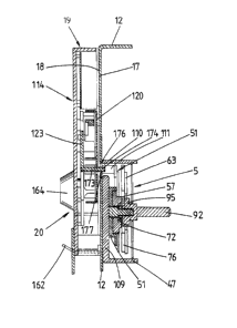
3Q recess 175 in the back wall 120 of the lock.
~ t is clear fro~ Fig. 12 how the permutation
lock 5 is arranged relative to the auxiliary lock 20 of
the safe door 3. Bsth locks 5 and 20 are arranged back-
to-back. The inner wall 12 of sa~e door 3 runs between
the two locks 5 and 20. The per~utation lock 5 ~s
~L~139~
- 25 -
attached to the inner side of the inner wall 12 ~1h~1e the
auxiliary lock 20 is located on the outer side 18 of
inner wall 12. As shown in Fiys. 2 and 12 the inner wall
12 is penetrated by an opening 176 and the au~iliary lock
20 is a~tached in such a way on inner ~?all 12 that the
free end 174 of projection 173 of the locking slide 123
passes through this opening 176. The permutation lock
5 is positioned in such a way that the extension 111 of
bolt slide 51 comes to rest above opening 176. Thé
lQ extension 111 of the bolt slide 51 is in contact with the
projection 173 of locking slide 123 thus forming a
coupled connection 177.
The operation of the safe according to the
invention is thus as follows:
If a person wishes to use the safe, for example
to store valuables safely, he must first open the safe
door, which has been left unlocked by the previous user.
Once the valuables have been placed in the safe he inserts
a coin 145 into the coin insertion plate 135 on auxiliary
lock 20. If the auxiliary lock is set up for two-coin
operation, then it is necessary to insert the requisite
two coins 145. The change over from sin~le-coin operation
to two-coin operation can be effected as already described.
Once the coins have been inserted, the user closes the
safe door 3 and then by operating the coding kno~s 7
selects his personal secret code (e.g. a number combination
1, 2, 3 or also a combination of letters such as A, B, C,
if the coding knobs are marked with letters). Then he
3Q locks the safe door 3. This is done by rotatin~ the
operating knob 6 of permutation lock 5. By actuating the
operating knob 6 the bolt slide 51 of the permutation
lock 5 is moved to the locked position and the-head section
53 of the bolt ~ngages in the striking plate system
installed in the door frame of the safe. As already
described, the displacement of the bolt slide 51 on the
1~897~Çi
- 26 -
one hand causes the combination to be stored and on the
other hand drags with it the projection 173 of the locking
slide 123 in the auxiliary lock 20. Since the user h~s
inserted a coin 145 into the auxiliar~ lock 20~ the
bolt slide 51 can simultaneou~l~ moYe the locking slide
123 to its fulle6t extent because, as already described,
the edge of the coin li~ts the locking pawl 128 so that
no resistance is offered to the displacement of the locking
slide 123. If however the user does not insert any coin
into the auxiliary lock 20, the locking slide 123 cannot
be fully displaced because the locking tooth. 130 of the
pawl 128 comes against. the locking shoulder 170 of recess
131; consequently, despite the coupled connection 177
with the bolt slide 51, the locking slide 123 cannot be
moved to its closed position. Thus, the permutation lock
cannot be closed. The locking procedure can only be
accomplished if a coin is inserted. As already described,
in the lock end position the lever 136 in the auxiliary
lock 20 is displaced so that the coin 145 falls out of
the coin exit opening 160 and reaches the coin collecting
. chamber 15 via the vertical coin chute 24 and the inclined
; coin chute (slide) 23 in safe door 3. The user now notes
his combination (if he has not already done so) and
scrambles the codin~ knobs 7.
If the user later wishes to open the safe door
3 he first selects his secret combination by rotating
the coding knobs 7 and th.is releases the permutation lock,
as already described. By operating the oper~ting knob
6 it is then possible to retract the ~olt slide 51 of the
permutation lock. ~he door of the safe can be opened.
Because of the coupled connection 177 unlocking the
permutation lock also returns the auxiliary lock 20 to its
ori~inal open position. ~he user, or another user, can
then make use of the safe again in the manner described.
: From the foregoing it is clear that the object
~8~7~i~
- 27 -
of the invention thus makes it necessary to insert a
coin each time in order to close the permutation loc~,
and each time the secret combination is stored. If the
user forgets his combination, an authorized person, e.g.
the hotel detective~ should be called who has a key to
unlock the fastening element 38 of panel 8. When he
opens the fastening element 38 he can remove panel 8.
After also removing panel 179 the selected combination
can be discovered, in the manner already described, by
setting the markings in the corresponding openings 180
in the lid 178 of the case of the permutation lock. The
safe door can then be opened~ Once this is done, the
additional panel is ~itted with a new seal and the
panel 8 is locked by operating the fastening element 38.
The coin collecting chamber 15 can be emptied
without the user of the sa~e having to be present because
it is not necessary to open the safe door 3 to get at the
money. Instead, an authorized person can use a key to
unlock the fastening element 29, then remove lid 11,
thus giving access to the coin collecting chamber 15.
The authorized person thus does not have access to the in-
terior of the safe because the coin collecting chamber 15
is screened off from the safe by the inner wall 1~.
Fig. 13 shows a top view of the permutation
lock 5 after it has been removed from the safe door 3.
The permutation lock 5 is in the closed position so that
the head section 53 of the bolt projects from the lock
case 47. The operating knob 6 is in a position corresponding
to the closed position of the vault. In addition, Fi~. 13
shows that the in~ide of th~ lock case 47 is covered by
the lock case lid 178. The latter possesses openings
through which pass the shaft 22 of the operating knob
6 and the shafts of the coding knobs 7. A covering panel
179 is arranged on the lock case lid 178 and this panel
cannot be removed until at least seal 83 has been broken;
~397~i
- 2~ -
removal of the panel exposes the openings 118 in the
lock case lid 178 (see Fig. 14); these openings are
arranged in each case to the right of the corresponding
shafts 90 to 92 of the coding knobs 7. The sealing of
the panel can be effected for example by pro~ing a hole
181 on the covering panel 79 and an eye 182 on the lock
case lid 178, and *hrough this hole and eye a safety ~lire
is then passed whose ends are joined together by a seal
183. Markings allocated to the coding knobs 7 can be
arranged on the covering panel 79.
In accordance with Fig. 14 the openings 180
in the lock case lid 178 are exposed when the covering
panel 179 is moved. The markings 102 to 104 can be seen
in the holes when the permutation lock 5 is locked. These
markings 102 to 104 can for example take the form of red
dots. If the permutation lock 5 is in the open position
the markings 102 to 104 move out of the openings 180
in the direction of the arrow 184 so that they are no
longer visible. Similarly, the markings 102 to 104 are
not visible when the permutation lock is locked and the
combination code has not been set at the code knobs 7
because the markings are then moved out of the openings
180 by the pivoting of the locking slides 70 to 72.
Figs. 15-22 show a further embodiment of
the invention which differs from the previously described
embodiment in that a supplementary lock 61 is used. In
all respects the description of the previous e~bodiment
applies in this case as well.
It is in particular clear from ~ig. 1~ to 20
that the coin-operated release mechanism 19 has a
supplementary lock 61 on its front side ~0. This
supplementar~ lock 61 is fitted with a locking cylinder
62 possessing a key channel 63. Fig. 16 shot~s a rear
view of the supplementary lock 61. It is apparent from
1~8~7~;6
- 29 -
this Fig. that the lock is attached by means Of tT~70
screws 64 which pass through the front side 6q of the
coin-operated release mechanism 19. The locking cylinder
62 possesses a web 65 which is cylindrical in shape with
a flattened section 66. To this web 65 is attached a
radial stop pin 67 which can interact with the heads of
the screws 64. In this way, the angle of rotation of
the web 65 and thus of the key for the supplementary lock
is restricted, and the ends of the range of angular rota-
tion are defined by the contact made between the stoppin 67 against the heads of the screws 64. The supplemen-
tary lock is thus arranged in such a way on the coin-
operated release mechanism that its web 65 is located
below the pawl 128. This permits the following method
of operation:
Fig. 16 shows the supplementary lock 61 in
the open position in which the key 68 (see Fig. 20) of
the supplementary lock 61 can be freely inserted into or
removed from this lock. The flattened section 66 of the
web 65 is located at a distance from the pawl 128 of the
lock 20 which takes the form of a coin-operated release
mechanism 19. In this position the stop pin 47 is in
contact with the head of the lower screw 64. If the key
68 is now introduced into the key channel 63 and rotated,
the web 65 is also rotated and with it the stop pin 67
which comes to rest against the head of the upper screw 64,
and at the same time the position of the flattened section
56 of web 65 is changedO In this position the cylindrical
surface Ç8 of web 65 acts against the underside of pawl
128 which is then lifted and caused to rotate about stud
127. Locking tooth 130 of pawl 128 then occupies a posi-
tion in which is can no longe~ engage against shoulder
170 of recess 131 in locking slide 123 when the latter is
displaced in the opposite direction of arrow 159. When
the supplementary lock 61 is in this closed position the
lX8~37Çi~
- 30 -
locking slide 123, which for~s a lockin~ ele~ent 123',
of the coin-operated release mech~nis~ 1~ ls, released.
The supplementary lock 61 is e~uipped with
means which prevent the key 68 from being withdra,~n
when the lock is activated. Withdrawal of the ke~ 68
is possible only when the lock is in the open position.,
As already described, in addition to activating
the coin-operated release mechanism 19 by inserting a
coin 145, the locking slide 123 can also be displaced
in the opposite direction to the arrow 159 when the
supplementary lock 61 is activated so th,at its web, 65
lifts up the pawl 128. Consequently, the locking slide
can be displaced either by inserting a coin in the coin-
operated mechanism or by operating supplementary lock
61. The locking slide can also be moved if both such
actions are taken, although this is unlikely to happen
in practice.
It is clear from the foregoing that the
safe which is the object of the invention requires the
insertion of a coin, or the possession of a key to
operate the supplementary lock, each time the permutation
lock is activated. When the permutation lock is activated
the combination code is stored. All the new features
mentioned in the description and illustrated in the
drawings are essential to the invention even if they are
not explicitly claimed in the Claims section.