Note: Descriptions are shown in the official language in which they were submitted.
1289~56
.
-- 1 --
A CHEMICAL REACTION APPARATUS
Back round of the Invention
- g
1. Field of the Invention
This invention relates to a chemical reaction
apparatus which is not only applicable to certain fields
within the chemical industry such as biotechnology,
biochemistry and the like, but is also suitable for carrying
out research in biological chemistry, inclusive of
microbiology, or various kinds of chemical reaction tests
such as a clinical diagnosis. The invention relates more
particularly to a chemical reaction apparatus which is
adapted to allow chemical reaction in a capillary tube so
that a reaction test may be made in a simple and efficient
manner
2. DescriPtion of the Related Art
-- .
In general, methods and apparatus for performing
a chemical reaction by the use of many samples each in a
small quantity have recently shown rapid progress in the
development of techniques in the domain of clinical
diagnosis for use with immunochemical reactions. One of
these methods has proposed the fixing of an immunoreactive
substance on a tiny bead-of plasticO
Other methods have been disclosed in such printed
25 publications as European Patent Publication No 0182221-A2,
the inventor of which is also that of the instant
application. A reaction container for use with the
apparatus in which the aforementioned method is carried
out employs test tubes which are tilted and rotated such
as to significantly reduce the reaction time This will
fulfil the object of automatically treating many objects
to be tested at a higher speed.
Arts and apparatus using capillary tubes have
been suggested for performing an immunoreaction, one of
which is disclosed in, for example, International
Publication (PCT) No. W083/01119. The apparatus according
to this PCT invention is fabricated in such a manner that
~za~s~
a plurality of capillary tubes are vertically mounted on
the periphery of a rotary bed to allow an immunoreaction
to be performed in the capillary tubes. The advantages
derived from this apparatus lie in the fact that it is
simple and compact since a rapid reaction in the capillary
tubes eliminates the need for a stirring means.
When the blood of a patient is used as a sample
as in an immunoreaction, tests on a given volume of blood
have to be made for many items so that the volume of blood
to be used for one item is gradually reduced. However,
the aforementioned apparatus for performing a reaction in
capillary tubes has an advantage in that a small volume
sample is adequate to be useful as compared with the
conventional apparatus.
The method for use with a tiny plastic bead is
suitable for mass production wherein immunoreactive
substances are themselves coated to be the surface thereof.
The use of a bead for performing many immunoreactions
requires a complicated series of operations such as casting
the bead in the test tube, taking out the bead to wash from
the test tube, recasting the bead and adding a reagent
thereto and so on. For accommodating this, various
approaches have heretofore been made. For instancer various
automatic mechanisms have been proposed but they have
required a complicated mechanism and much time for the
reaction. They are not suitable for treatment of many
specimens at a high rate.
The European Patent Publication No. 0182221-A2
discloses an apparatus which employs instead of the bead
mentioned above a test tube on the inner surface of which
the immunoreactive substance is coated, the test tube being
tilted and rotated to significantly reduce the reaction
time required. An apparatus of this class is most suitable
for the purpose of automatically treating many specimens
at a high rate as compared with the method for use with
a bead.
.
.:
.
,
.
,
1289~356
~ 3 --
However, this will render the operation of fixing
the immunoreactive substance on the inside of the test tube
very complicated and production costs will become high as
compared with use of the surface of the bead. More
specifically, this operation requires injection of a
solution of the immunoreactive substance in a given quantity
into the test tube such as to leave it as it is for a given
time, and then removal of the solution from the inside,
washing and drying the test tube, and so on. In contrast,
according to the bead method, the object is effectively
attained by casting many beads in the solution of the
immunoreactive substance, and the subsequent washing and
drying are readily facilitated to be made this method
suitable for mass production. For clinical examination,
however the bead method is inconvenient to the user but
ready for production whereas the tube method is convenient
to the user but complicated in manufacture.
An operation for coating the immunoreactive
substance on the inner surface of a capillary tube is very
simple and easy as compared with the test tube operation.
More specifically, it is similar in manner to the bead
method in that a bundle of capillary tubes is vertically
immexsed in a solution of the immunoreactive substance so
that the capillary tubes are readily filled with the
solution from their lower ends to the center thereof. The
capillary tubes are left as they are for a given time and
at a certain temperature, and are then taken out for the
washing and drying steps. Although the immunoreactive
substance is coated to the exterior of the capillary tubes,
the reaction may be performed without any difficulty when
they are used with only the insides thereof involved in
the reaction. And the capillary tube has a smaller diameter
than that of the test tube so that the volume ratio of the
coated immunoreactive substance to a liquid specimen is
increased, resulting in a very quick reaction, and thereby
eliminating the need for rotation of the test tube in order
to facilitate the reaction as is necessary in the test tube
' ' ~ . ' , . : '
~ ~ :
9~56
4 --
method. For this reason, if an apparatus is devised which
uses the capillary tubes such as to positively and simply
handle a many specimens in an automatic manner, the
capillary tube itself is tiny and the machine can thus be
made compact so that quick mass treatment may be
accomplished at a high treatment rate.
International Publication (PCT) No. WO83/0119
discloses an apparatus for use with capillary tubes which
employs a combination of coating the immunoreactive
substance on the inner surface of the capillary tube and
an automatic machine for successively performing the
immunoreaction such as to improve on the well known method
for coating various chemical substances to the inner surface
of the capillary tube.
The apparatus disclosed in the aforementioned
publication is constructed such that each of the capillary
tubes is always held vertically for various operations.
With this arrangement, when the reagent liquid to be charged
in the capillary tube is increased the surface tension in
the capillary tube cannot sustain the weight of the liquid
even if the amount of the liquid is very small.
Consequently a portion of the liquid flows out of the tube,
thus preventing the apparatus from the performing an
accurate chemical reaction.
When each of the capillary tubes is made of
hydrophilic material such as glass and the lower end of
each of the tubes is ln contact with the surface of water,
water is sucked into the tube by a capillary phenomenon
and rises therein. The water rises to a level inversely
proportional to the inner diameter of the tube. This will
be shown in the following table prepared by the inventors
of the subject application on the basis of their
experiments.
~,:
: ~ .
:.
Table
,
inner diameter
(mm) of glass raised level
capillary tube (mm) of water
.
1.7 9.5
1.3 10.5
0.95 18.0
The length of the vertically held capillary tube
which is capable of sustaining liquid with which it is
completely filled is limited to what is shown in the table.
The capillary tube to be used in the apparatus disclosed
in the aforementioned publication thus must be quite short.
Sample and reagent liquids may be injected into
each of the capillary tubes vertically held in this
apparatus in such a manner that the liquid contained in
a cup mounted on the top of the tube contacts the tube
through perforation formed in the bottom of the cup.
In this connection, a longer capillary tube holds
the liquid onLy in the lower portion thereof. Even if the
capillary tube is short, the liquid drops fall from the
lower end of the tube or are suspended therefrom when the
volume of the liquid contained in the cap is more than the
capacity of the tube. Thus~ the volume of liquid which
drains into a measuring system is inaccurate in quantity.
In order to attain accuracy, an accurate micropump needs
to be provided. It is, therefore, difficult to secure
simplicity of structure with use of a capillary tube instead
of a micropump as proposed in the aforementioned
publication. Since an extremely short capillary tube has
to be used, the mechanism for handling such capillary tube
is necessarily complicated. Further, in the aforementioned
apparatus, the capillary tube is held vertically and mounted
on the periphery of the rotary base as a conveyor device.
A specific device is required for mounting the tube and
troubles are then involved in mounting and demounting the
.; '- ,' - ' , ' ' ,
.
1~89~5~
-- 6 --
tube.
SUMMARY OF THE INVENTION
It is a feature of one embodiment of the invention to
provide a chemical reaction apparatus which is simple in
structure and capable of allowing a chemical reaction with a
reagent and the like to take place in such a manner that an
accurate chemical reaction is performed, the structure being
such that it is easy to mount and demount the capillary tube
without requiring any stirring device and metering device
for a reagent.
According to the present invention there is provided a
chemical reaction apparatus comprising: a plurality of
capillary tubes, conveying means for holding the capillary
tubes substantially horizontally and for conveying the tubes
along a conveyance path; and feeding means mounted along the
conveyance path for feeding a liquid for use in a chemical
reaction to the interior of the capillary tubes, the feeding
means including at least one vertically disposed liquid
specimen cylinder for containing a liquid specimen so that
drops of the liquid specimen are suspended from a lower end
thereof, the liquid specimen cylinder being mounted so that
an end of each capillary tube is sequentially disposed
immediately adjacent the lower end as the capillary tubes
are conveyed along the conveyance path so that the end of
the capillary tube is brought into contact with a drop of
liquid specimen suspended from the liquid cylinder, whereby
each capillary tube is filled with liquid specimen by
capillary phenomena immediately upon contact of the drop
with the end of each tube.
In accordance with the chemical reaction apparatus of
the present invention, the capillary tubes are always
conveyed while being held in a horiæontal position by the
conveying device whereas the reagent and the like are fed to
the interior of the tubes from the feeding device. If the
reagent and the like contacts the ends of the capillary
398S6
- 6a -
tubes, it is instantaneously charged into the tubes. At
this moment, the capillary tubes are held substantially
horizontal so that the force of gravity which tends to cause
the liquid in the tube to drop from the tubes is smaller
than the force of the surface tension by virtue of which the
liquid is retained in the tubes. As a result, the reagent
and the like remains in a stable condition while these
discharged into the entire length of each of the tubes. The
capillary tubes are each time supplied with a constant
volume (equal to the internal volume of the tube) of the
reagent and the like.
,,.'~
,. . . .
'' ~ .
.
.
. .
1'2~9~
For this reason, the reagent and the like used
in the chemical reaction are always maintained at a constant
volume r thereby allowing accurate chemical reactions to
be performed.
Further~ since the capillary tubes are held and
conveyed by the conveying device while in a horizontal
position, the conveying procedure may be accomplished simply
by laying the tubes on the conveying device. The device
used for holding the tubes on the conveying device or
demounting the tubes may thus be very simple.
BRIEF DESCRIPTION OF THE DRAWINGS
Fig. 1 is a perspective view of an apparatus
embodying the present invention,
Fig 2 is a fragmentary sectional view of the
neighborhood of a hopper of the apparatus,
Fig 3 is a sectional view of a station for
washing a specimen to be examined,
Fig 4 is a schematic view of one form of a light
emission station,
Figs. 5 and 6 are partial perspective views
showing different forms of a belt conveyor,
Fig 7 is a perspective view showing a plurality
of capillary tubes fixed to a sheet,
Fig. 8 is a partial perspective view showing
another embodiment of a conveying device,
Fig. 9 is a plan view of a different embodiment
of the conveying device,
Fig 10 is a plan view of the same,
Figs. 11a and 11b are schematic front and side
views of another form of the light emission state in section
as used in a measuring device,
Fig. 12 is a back plan view of the sheet with
the capillary tubes shown in Fig. 7,
Fig. 13 is a perspective view showing another
embodiment of the sheet with the capillary tubes, and
:
-
. :
-
~2~9856
-- 8
Fig, 14 is a plan view showing a still another
embodiment of the sheet fixed with the tubes.
DESCRIPTION OF THE PREFERRED EMBODIMENT
An embodiment in which the invention is applied
to an immunoreactive apparatus will first be explained with
reference to Figs, 1~ 2 and 3.
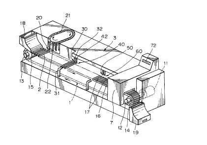
Fig. 1 is a perspective view of an apparatus
according to an embodiment of the invention, wherein numeral
1 is a belt conveyor adapted for use as a device forconveying a plurality of capillary tubes 2 and comprises
a drive shaft 12 driven by a motor 11 with a reduction gear,
a driven shaft ~3 rotatably supported on a body of the
apparatus, the two shafts 12, 13 being mounted on the
apparatus at opposite ends thereof, and an endless conveyor
belt 16 of material such as polyurethane resin trained in
parallel fashion over pulleys 14 and 15 mounted on the
respective shafts 12, 13.
The motor 11 with the reduction gear is adapted
to rotate the drive shaft 12 such as to put the upper run
of the conveyor belt 16 in a stretchecl state, In Fig, 1,
the drive shaft 12 is rotated in the clockwise direction.
The motor 11 with the reduction gear may be rotated at a
constant speed or intermittently rotated by means of
microprocessor control. A detector device such as an
optical sensor may be provided for detecting the position
of the conveyor belt 16 such as to control rotation of the
motor.
The conveyor belt 16 is mounted such as that its
upper run is substantially horizontal, Grooves 17 are
formed at a constant distance and perpendicular to the
direction of the belt running on the periphery of the
conveyor belt 16 whereby the capillary tubes 2 may be held
in the grooves. Although the number of grooves 17 may be
selected depending upon the object of a particular
application, 30 - 200 may be regarded as preferable. In
this connection, it is noted that a timing belt with
.
-
- ' '
. : :
356
g
corrugations formed on the inside thereof is used as the
conveyor belt 16 such as to mesh with pulleys which are
also corrugated. This will avoid slippage between the belt
and the pulleys. The grooves 17 may take any configuration
so long as the capillary tubes 2 may be stably held therein.
For instance, a plurality of comb teet:h may be provided
to serve as these grooves.
A hopper 18 is disposed upwardly and in the
neighborhood of one end of the driven shaft 13 of the belt
conveyor 1 for feeding the capillary tubes 2 to the conveyor
belt 16. Fig. 2 is a schematic section of the neighborhood
of the hopper 18. Each of the tubes 2 is formed of glass,
polyethylene or other plastics and is so dimensioned as
to have an inner diameter of 1 - 1.5 mm and an overall
length of 5 - 8 cm, the opposite ends of each of the tubes
being open. Before entering the hopper 18, the insides
of the capillary tubes are coated with the immunoreactive
substance, such as an antibody or the like, by way of
immersion or other means. The capillary tubes drop from
the hopper 18 by the force of gravity and are indexed one
by one to be fed to each of the grooves 17 on the top
surface of the belt where they are held in place. Then,
the tubes are carried on and conveyed by the conveyor belt
16.
Consequently, no specific provision or operation
or the like is required for mounting the capillary tubes
2 on the belt conveyor 1 which serves as the conveying
device.
A casing 19 is provided downwardly of the
neighborhood of one end of the drive shaft 12 for the belt
conveyor 1 for receiving the processed capillary tubes.
The fully processed capillary tubes drop from the right
end of the conveyor belt 16 and are successively received
in the casing 19. No specific provision or operation or
the like is required for demounting the tubes 2 from the
belt conveyor 1.
.
35~
- 10 -
Numeral 3 designates a feeding device for reagent
and the like which is disposed along the belt conveyor 1
and which feeds a liquid specimen to be examined and an
immunoassay reagent solution and the like to the interior
of the tubes 2. In this instance, the reagent feeding
device comprises a supplying station 20 for supplying the
successively different liquid specimens to be examined,
a liquid specimen washing station 30 for washing the
interior of each tube 2 after a predet:ermined time and for
discharging the reacted liquid specimen, an enzyme labelled
antibody solution supplying station 40 for feeding an
immunoassay reagent solution such as an enzyme labelled
antibody solution into each tube 2, a reagent washing
station 50 for discharging any enzyme labelled antibody
solution which has not bonded upon washing the interior
of each tube 2 after a predetermined time, and an enzyme
substrate solution supplying station 60 for feeding an
enzyme substrate solution into each tube 2. These stations
are successively arranged along the conveyor belt 16.
The liquid specimen supplying station 2 comprises
a feeder device 21 operable in association with the belt
conveyor 1 and a plurality of liquid specimen cylinders
22 for containing blood, spittle or urine and the like,
the cylinders 22 bein~ mounted on the feeder device. The
specimen liquid forms drops at the lower end of the cylinder
22, the drops being suspended therefrom. Each of the
capillary tubes 2 is filled with the liquid specimen by
a capillary phenomenon which occurs immediately upon contact
with the end of each tube.
According to the present invention, the capillary
tubes 2 are held substantially horizontal so that the force
of gravity by which the liquid in the tubes 2 would tend
to flow from the interior of the tubes is smaller than the
force of the surface tension by which the liquid is retained
in the tubes. The liquid specimen is stable in a charged
condition along the full length of the tubes 2. When the
liquid specimen suspended from the lower ends of the
- . , ~ . .
' . ~
'
-
12~ 5~;
- 11 -
cylinders 22 is increased by a greater volume than the
internal volume of the tubes, a constant volume (equivalent
to the internal volume of the tubes) is always supplied
to and charged in the tubes 2.
Referring to Fig. 3 which shows the liquid
specimen washing station 30 in section, this washing station
will now be described in greater detail. Suction pipes
31 connected to a suction device (not shown) are disposed
on one side of the conveyor belt 16 and in the proximity
thereof such as not to contact the tube 2. With this
non-contact arrangement, no impurities are attached to the
tubes, thereby ensuring that an accurate reaction is
performed. A cylinder 32 for containing washing liquid
is provided on the other side of the conveyor belt 16 and
forms drops at the lower end of the cylinder 32. The
capillary tubes 2 are filled with washing liquid by a
capillary phenomenon when the ends of the tubes contact
the drops.
The suction device is controlled by, for instance,
a micro-processor or the like, and is actuated in
association with the movement of the belt conveyor 1. After
the tubes 2 have been filled with the liquid specimen via
the liquid specimen cylinder 22, the suction device is
caused to suck and discharge the liquid with a lapse of
a predetermined time (for instance, 10 min.), and further
to continuously for intermittently suck the washing liquid
from the tubes 2 for a fixed time, thereby washing the
interior of the tubes 2.
The enzyme labelled antibody solution supplying
station 40 is provided with a cylinder 42 similar to the
washing liquid cylinder 32 on one side of the conveyor belt
16. The capillary tubes 2 as washed are filled with the
enzyme labelled antibody solution by a capillary phenomenon.
The enzyme labelled antibody solution is in a stable
condition while the tubes 2 are filled with the antibody
solution over the entire length thereof, thereby always
supplying and charging a constant volume (equivalent to
~89~6
- 12 -
the internal volume of the tubes) into the tubes 2.
The reagent washing station 50 is similar to the
liquid specimen washing station 30 in structure. The
capillary tubes 2 are filled with the enzyme labelled
antibody solution by the antibody solution cylinder 42.
The solution in the tubes is sucked and discharged with
a lapse of a predetermined time, thereby washing the
interior of the tubes.
The enzyme substrate solutic,n supplying station
60 is of the same structure as that of the enzyme labelled
antibody solution supplying station 40 and is adapted to
charge an enzyme substrate solution into the capillary tubes
2. In this instance, the tubes 2 are always filled and
supplied with a constant volume (equivalent to the internal
volume of the tubes) of the enzyme substrate solution.
Numeral 7 is a measuring device which is disposed
such as to cover the conveyor belt 16 in the proximity of
the right end thereof for measuring the optical density
of the reactive solution in each tube 2. In this
connection, it is noted that a spectrophotometer, a
fluorophotometer or the like may be used as the measuring
device~ The antigen concentration in the liquid specimen
is calculated by a microcomputer on the basis of the optical
density of the reactive solution. Numeral 72 is an
indicator for digitally displaying the result of the
measurement.
For measurlng the optical density of the reactive
solution as shown in Fig 4, an optical fiber 71 having
a tapered emitting end is inserted into the end of each
tube 2 to emit light The light which passes through the
entire length of each tube 2 may thus be detected. In this
manner, the fiber emitting end is inserted into the end
of each tube 2 so that any light emitted is reflected by
the inner periphery wall and passes therethrough. This
will prevent any excess light which may otherwise pass
through the blank for each tube from being incident, thereby
ensuring an accurate measurement. As shown in Fig. 11,
,
. ~ . ' ~ :
..
': - '
, ~ ' .
1;~8~
- 13 -
the light as detected may pass vertically through each tube
2 which is held horizontal on the conveyor belt 16.
~ ow, operation of the aforementioned embodiment
will be explained by quoting an example in which an enzyme
immunoassay is carried out on a carcinoembryonic antigen
(hereinafter referred to as "CEA"), wherein the CEA
concentration in the liquid specimen is to be measured.
Coated to the capillary tubes are an anti-CEA
antibody as an immunoreactive substance, an enzyme labelled
anti-CEA antibody as an enzyme labelled antibody, hydrogen
peroxide as a substrate, orthophenylenediamine as a color
producing reagent, and peroxidase as a labelled enzyme.
The capillary tubes 2 are adapted to allow the
anti-CEA antibody to be coated to their interior surfaces
and are put in the hopper 18. The liquid specimen is
contained in each liquid specimen cylinder 22 and is mounted
on the feeder device 21 of the liquid specimen supplying
station 20.
Upon movement of the belt conveyor 1, the
2C capillary tubes 2 are successively indexed to fall out of
the hopper 18 as the conveyor belt 16 moves. The tubes
2 are held horizontal, one by one, in the respective grooves
17 formed in the belt, and are then conveyed by the conveyor
belt 16.
The capillary tubes 2 at the liquid specimen
supplying stati.on 20 are fllled with the liquid specimen
so that the CEA contained in the specimen are bonded to
the anti-CEA antibody coated to the inner surface of each
tube 2, thereby performing the immunoreaction.
The conveyor belt 16 is gradually and slowly moved
while the tubes 2 proceed with the immunoreaction taking
place therein. With the lapse of a predetermined time (for
instance, 10 min.) after the tubes have been filled with
the liquid specimen, the tubes 2 at the liquid specimen
washing station 30 are washed so as to discharge the liquid
contained therein other than the CEA bonded to the anti-CEA
antibody.
:
~39~3~6
- 14 -
At the enzyme labelled antibody solution supplying
station ~0, the capillary tubes 2 are filled with the enzyrne
labelled anti-CEA antibody, and the enzyme labelled CEA
antibody is coated to the inner surface of the tubes in
a sandwich fashion by virtue of the CEA coated to the inner
surface of the tubes. The tubes 2 are washed at the enzyme
labelled antibody washing station 50 after the lapse of
a predetermined time (for instance, 10 min.) and all the
enzyme labelled antibody solution which has not been bound
in the tubes is washed away.
Subsequently, at the enzyme substrate solution
supplying station 60, a mixture solution of hydrogen
peroxide and orthophenylenediamine is charged into each
tube 2 so that oxygen which is formed from hydrogen peroxide
by the enzyme (peroxidase) of the enzyme labelled antibody
coated in each tube 2 reacts with the orthophenylenediamine
whereby the reactive solution produces a color.
In the aforementioned reaction processes, the
capillary tubes 2 are always held substantially horizontal
and in a stable manner in the grooves 17 formed in the
conveyor belt 1. When the capillary tubes are filled with
various reagents, these reagents are retained in the tubes
by a capillary phenomenon over the entire length of the
tubes without voids. Accordingly, the volume of the
reagents to be used for reaction is equivalent to the
internal volume of the tubes~ thereby ensuring an accurate
reaction without requiring any measuring device.
The colored capillary tubes 2 are moved to the
measuring device 7 after a predetermined time (for instance,
10 min.) has elapsed, and then the result of the reaction
is read from the tubes by a chromometer. The value of what
is read is computed by a microcomputer and the like and
is digitally displayed by, for instance, an indicator 72
The capillary tubes 2 which have been subjected
to all the processes drop from the right end of the conveyor
belt 16 and are successively received in the casing 19.
~39~;~
- 15 -
The aforementioned embodiment will now be
described by exemplifying a case in which an AFP
(~-fetoprotein) concentration in the liquid specimen is
measured by the immunoassay of AFP.
Coated to the capillary tubes are an anti-AFP
antibody as the immunoreactive substance, an enzyme labelled
anti-AFP antibody as the enzyme labelled antibody, hydrogen
peroxide as the enzyme substrate, orthophenylenediamine
as the color producing reagent, and peroxidase as the
labelled enzyme.
The anti-AFP antibody is coated to the inner
surface of each tube 2 and then the inner surface of each
tube is further coated with the enzyme labelled antibody.
The capillary tubes are frozen, dried, and accommodated
in the hopper 18. The liquid specimen is contained in each
of the liquid specimen cylinders 22 and is mounted on the
feeding device 21 of the liquid specimen supplying
station 20.
When the belt conveyor 1 is actuated, the
20 capillary tubes 2 drop out of the hopper 18 as the conveyor -
belt 16 is moved and are then held one by one substantially
horizontal and in parallel with each other in the grooves
17 formed in the belt The tubes 2 are then conveyed by
the conveyor belt 16.
At the liquid specimen supplying station 20, each
tube 2 is filled with the liquid specimen to allow the
immunoreaction to be performed
The conveyor belt is slowly moved while within
each tube 2 the anti-AFP antibody coated to the inner
surface thereof promotes a reaction with the AFT present
in the liquid specimen and the immunoreaction of the AFP,
which has reacted on the anti-AFP antibody coated to the
inner surface of each tube, with the enzyme labelled
anti-AFP antibody proceeds. After a predetermined time
(for instance, 15 min.) has elapsed following replenishment
of the liquid specimen, each tube 2 i9 washed at the reagent
washing station in order to discharge any liquid which is
- . ' .:
121~
- 16 -
not involved in the reactions of the AFP bonded to the
anti-AFP antibody bonded to the inner surface of each tube
and of the enzyme labelled anti-AFP antibody bonded by
the AFP.
Since the reactions are performed all at once
up to this stage, the liquid specimen washiAg station 30
and the enzyme labelled antibody solution supplying station
40 are kept out of operation.
Subsequently, at the enzyme substrate solution
supplying station 60, a mixture solution of hydrogen
peroxide and orthophenylenediamine is charged into each
tube 2 so that oxygen which is formed from hydrogen peroxide
by the enzyme (peroxidase) of the enzyme labelled antibody
coated in each tube 2 reacts on orthophenylenediamine to
cause the liquid to produce a color.
The colored capillary tubes 2 are moved to the
measuring device 7 after the lapse of a predetermined time
(for instance, 10 min.) and then the result of the reaction
is read from the tubes by a chromometer. The value of what
is read is computed by a microcomputer and the like and
is digitally displayed by, for instance, an indicator 72.
The capillary tubes 2 which have been subjected
to all the processes drop from the right end of the conveyor
belt 16 and are successively received in the casing.
Figs. 5 and 6 show a modified form of a belt
conveyor used as the conveyor device,
For the purpose of measuring the optical density
of the reaction solution by means of the measuring device
7 in order to emit a measuring beam perpendicular
(Y-direction) to the instant apparatus, perforations 118
are formed on the bottoms of grooves 117 in a conveyor belt
116 to allow the beam to pass through the perforations as
shown in Fig. 5. Alternatively a pair of conveyor belts
216 with the tubes 2 carried thereon are spaced away from
each other in parallel therewith to allow the measuring
beam to pass through clearances defined by the belts and
tubes as shown in Fig. 6.
.
..
lZ89~56
- 17 - -
Although the embodiments ha~e been described with
reference to capillary tubes which are successively supplied
one by one, as shown in Fig. 7, a plurality of the tubes
2 may be arranged in parallel with each other on a sheet
S 4 and the like made of paper or plastic and may be bonded,
mounted or joined by an adhesive or any other suitable
means. This will enable one to enter various legends,
displays and records in the sheet for convenience of
practical use. Numeral 5 is an aperture through which the
measuring beam passes.
Although the belt conveyor is used in this
embodiment as a conveyor device, the invention is not
limited thereto. As shown in Fig. 8, for example, a disc
301 in the doughnut form for rotating the conveyor device,
may be provided on its surface with radial grooves 317 to
carry the tubes 2 thereon. 318 is a rotating shaft. In
this instance, it is also convenient for various controls
to hold the capillary tubes by the conveyor device at
regular intervals (equal angles). As is similar to the
arrangement shown in Fig. 7, a pLurality of the capillary
tubes may be radially mounted on the sheet in advance.
The chemical reaction apparatus of the present invention,
as shown in Figs. 9 and 10 may use another form of a
conveyor apparatus in which a circular rotary member 401
is rotatable upon the horizontal axis and is provided on
its periphery with grooves 417 to receive therein the
capillary tubes 2 to be conveyed.
Although the embodiments have been described with
respect to the immunoreaction apparatus embodying the
present invention, the invention may include those
applicable to various types of the chemical reaction
apparatus.
According to the chemical reaction apparatus of
the invention, the capillary tubes are horizontally held
to perform the chemical reaction so that the volume of
reagent and the like which are supplied to and filled in
the tubes for use in reaction are always constant thereby
. : , , - ,
.
.
1~8~13S6
- 18 -
performing a very accurate chemical reaction without
requiring any metering device. Accordingly, the apparatus
may be simplified to not only reduce production costs but
also enable anyone to readily use it thereby facilitating
maintenance of the apparatus. Advantages derived from the
instant apparatus are in that either the device for holding
the tubes in the conveyor device or another device for
demounting the tubes is very simple in structure and
operation for convenience to its use. Thus, the chemical
reaction apparatus may be obtained which is suitable for
automatic chemical reaction and is ready for use.
In Fig. 12, there is shown a back side of the
sheet fixedly mounted with the capillary tubes. There,
to a surface side of the sheet 4 made from paper or plastic
materials, there are fitted a plurality of (for example,
ten, as illustrated in the drawing) capillary tubes so that
they are aligned to each other with equal distances
therebetween and so that their both ends extend outwardly
a little from the sheet 4. The capil]ary tubes are same
in their shapes and sizes, and are coated at their inner
front surfaces with an immunoreactive substance. While
the tubes 2 are fixed onto the sheet 4 in this invention
most commonly by an adhesive, they may be fixed by any other
conventional means such as heat welding, or they may be
made integral with the sheet 4 by means of an integral
plastic molding method.
On the back side of the sheet 4, there are formed
columns 6 in which necessary data for each tubes can be
written. The columns 6 are consisted of printed frames
of a predetermined shape within which the data can be
recorded by pencil, ball-point pen, and the like. Said
columns 6 could of course be eliminated totally or partially
or could be provided only on the front side of the sheet
4, or would be provided on the both sides. It is feasible
that data are printed onto the columns automatically with
the operation of a chemical reaction treating apparatus.
Numeral 5 indicates windows through which light is
.
.~ .
1~89~5~
- 19 -
transmitted.
Said light-transmission windows could be made
continuous as shown in Fig, 13, to form a continuous slit
opening 5a or any other desired shape. Or, the sheet 4a
could be made by itself as light-transmissible.
In Fig. 14, there are shown the plurality of
capillary tubes 2 which are aligned to each other with an
equal angular distance on a fan-like shaped sheet 4b. This
kind of arrangement of capiLlary tubes can advantageously
be employed in connection with the conveying device shown
in Fig. 8.
The employment of a plurality of capillary tubes
which are aligned under a predetermined pattern as a unit
as described above, enables it for an operator to deal with
them readily in order and in alignment by unit by unit so
that the capillary tubes can always be distinguished to
each other. Chemical reactions thereby can be made very
accurately since the capillary tubes can hardly make a
contact to each other, and can never be mixed to each other.
In addition to these effects, there are several other
advantageous points including that data on each capillary
tubes can readily and easily be recorded on a very sheet
on which the tubes are mounted.
It will be appreciated that the invention is not
limited to use of the particular construction illustrated,
but includes variants and alternatives within the spirit
and scope of the claims.
. :
,