Note: Descriptions are shown in the official language in which they were submitted.
~Z9~0~8
` ~ ,...
AUTOMATIC HEADLAMP DIMMING SYSTEM
The present invention is directed to the field
of automotive headlamp systems and more specifically to
the area of automatic control for such systems in order
to down-switch the beam patterns and prevent interfering
glare to oncoming drivers.
In U.S. Patent Nos. 3,373,311 and 3,894,227
inventions are disclosed which provide "tri-beam"
headlighting systems of low, mid and high beam patterns
controlled by various manually actuated swit~hes to
obtain the appropriate selection.
Low-beam headlamps are designed to provide
adequate illumination for a vehicle operator without -
producing unacceptable glare for operators of opposing
or oncoming vehicles. The low-beams are directed so
that the high intensity projection areas of its baam
patterns are directed sightly down and to the right for
countries of the world which utilize right hand traffic
patterns. In left hand traffic patterns, the low-beams
are aimed down and slightly to the left~ (For the
remainder of this discussion right hand traffic
patterns will be assumed.) With the use of low-beams,
the left lane, the mid foreground and the right lane,
beyond approximately 150 feet, are not intensely
lighted. On the other hand, high-beam patterns are
generally directed 50 as to cov~r much wider horizontal
and vertical anqles that will cause glare in the eyes of
drivers o~ oncoming vehicles even on straight roads.
~, ;,, .
\
-- 2 --
The mid-beam concept, although first disclosed
several ye~rs ago, provides more usable light directed to
the right edge of the driving lane without causing
increased glare to opposing drivers, while on straight
roads. However, the mid-beam concept has not been
adopted by the industry. It is believed this reluctance
to adopt such an improvement in headlighting sy~tems is
based upon the fact that when a mid-beam system is
utilized, there are still those instances when the
mid-beams have to be down-switched to the low-beams in
order to prevent glare from interfering with the vision
of the oncoming driver. For instance, when the road
geometry varies (curves and hills) or the lamps are
misaimed so that they could cause the high intensity
projection areas of the mid-beam pattern to-be directly
aimed at opposing dri~ers, down-switching of the lights
is required. Taking into consideration the
aforementioned patents it is believed that such systems
of manually down-switching from mid to low-beams by a
vehicle operator would require the operator to have z
sophisticated understanding of the system concepts in
order to appreciate the necessity of when to manually
down-switch the beams. It is clearly evident that a
manually controlled mid-beam system is not practical,
since it has not been adopted by the industry.
Applicants have appreciated that it would be desirable to
have an automatic headlamp control system, but such
control systems presently available for high-beam
down-switching will not function for a "tri-beam"
headlighting system. U.~. ~atents 3,177,397; 4,599,544;
and 4,645,975 are t~pical of such high-beam control
systems.
Applicants have invented a unique system which
automatically determines the appropriateness of
down-switching from either the high to mid, high to low,
or mid to low beams without the need for manual
intercession by the vehicle operator. By providing a
conventional high-beam sensor, a mid-beam sensor which
is uniquely configured to sense the presence of oncoming
vehicles in the mid-beam pattern projection area and a
unique control circuit, the automatic down-switchiny is
achieved.
Accordingly, in one aspect of the present
invention there is provided a method o* controlling the
lo down-switching o~ a multibeam pattern headlamp system in
a vehicle when opposing vehicles approach within the
corresponding beam pattern, comprising the steps of;
providing headlamps on the vehicle for projecting a
plurality of predetermined high intensity patterns
directed outwardly from the vehicle in overlapping
areas; providing a source of electrical energy for
energizing the headlamps; providing a switching means
that is controllable to connect the source of electrical
energy to selected headlampsi providing a first sensor
for sensing the presence of headlamp xadiation from
oncoming vehicle headlamps over a wide range including
the overlapping areas of the beam patterns and
indicating the presence when the oncoming radiation is
sensed as being above a predetermined threshold;
providing a second sensor for sensing the presence of
headlamp radiation from on~oming vehicle h~adlamps
within a limited area of the overlapping beam patterns
corresponding to one of the beam patterns and
indicating the presence when the intensity of the
oncoming radiation is sensed as being above a
predetermined threshold, and- controlling the switching
means in response to the indications from the first and
second sensors in order to down-switch the headlamp beam
patterns by disconnecting the source oi electrical
energy from appropriate headlamps and restoring the
connections when the first and second sensors cease to
~2~
3a
provide the indications.
In another aspect of the present invention,
there is provided an apparatus for controlling the
down-switching of a multibeam pattern headlamp system in
a vehicle when opposing vehicles approach within the
corresponding beam patterns, comprising; headlamps on
the vehicle for projecting a plurality of predetermined
high intensity patterns outwardly from and forward of
the vehicle in overlappiny areas; means for providing a
lo source of electrical energy for energizing the
headlamps; switching means controllable to connect the
source of electrical energy to selected headlamps; first
sensor means ~or sensing the presence of headlamp
radiation from oncoming vehicle headlamps over a wide
range including the overlapping areas of the beam
patterns and indicating the presence when the oncoming
radiation is sensed as being above a predetermined
threshold; second sensor means for sensing the presence
of headlamp radiation from oncoming vehicle headlamps
within a limited area of the overlapping beam patterns
corresponding to one of the beam patterns and indicating
the presence when the intensity of the oncoming
radiation is sensed as being above a predetermined
threshold; and means for automatically controlling the
switching means in response to the indications from the
first and second sensor means in order to down-switch
the headlamp beam patterns by disconnacting the source
of electrical energy from appropriate headlamps and
restoring the connections when the first and second
sensors cease to provide th~ indications.
The invention is described further, by way of
illustration, with reference to the accompanying
drawings, in which:
Figure 1 is an isocandella diagram showing
candle power contours of th~ high intensity portion of a
mid-beam pattern;
3b
Figure 2 illustrates a preferred geometric
relationship between a headlamp that generates a
mid-beam pattern and an associated mid-beam sensor;
Figure 3 is a schematic representation of a
mid-beam sensor such as is shown in Figure 2;
Figure 3A is a plan viPw of a mask employed in
the sensor shown in Figure 3;
Figure 4 is a schematic representation of a
second embodiment of a sensor such as is shown in Figure
2;
Figure 4A is a plan view of a detector array
employed in the sensor shown in Figure 4; and
Figure 5 is a schematic of a control circuit
employed to provide the automatic down-switching of the
present invention.
Referring to the drawings, the isocandella
diagram shown in Figure 1 is a gross plot of the high
intensity pattern as projected by a mid-beam headlamp
system. The diagram illustrates the high intensity beam
pattern over a projection area above
,~
v~
-- 4 --
and below a horizontal reference line, as well as l~ft
and right of a vertical center line coincident with th~
center line of the vehicle. The designated angled lines
on the diagram represent the perspective view of the
right edge of the right lane, the road center line, the
left edge of the left lane and the path of the eyes of an
opposing driver, as it would appear when viewed from the
vantage point of the left, outboard headlamp. It can
seen from the diagram in Figure 1 that one highest
intensity (5,000-20,000 cp) illumination area for the
mid-beam light projection is below the horizontal
reference when referenced to the left of the vehicle
center line and well below the path of opposing driver's
eyes. Also, the mid-beam pattern provides another
highest intensity illumination area both above and below
the horizontal reference to illuminate the right edge of
the right lane, when referenced to the right of the
vehicle center line.
By concentrating on the center of the diagram as
depicting the distant horizon on a flat straight road, it
can be seen that the normal areas of projection by the
mid-beam pattern would not cause irritating glare to be
present in the eyes of an opposing driver. However if
one imagines that the road curves off to the right, or
that the center portion is a hill crest below the
horizontal reference, the high intensity illumination
pattern will intersect the line designated as the path of
an opposing driver's eyes. In those instances, it is
necessary to down-switch the beam to the low-beam
pattern.
In the present invention, it is intended that,
in normal use, the mid-beam headlamp will be on and that
a mid-beam light sensor be provided which senses the
presence of headlamps from only those oncoming vehicles
that enter into the projection areas of the mid-beam
9~
pattern. When the mid-beam light sensor detects the
presence of opposing headlamps in the projection areas of
the mid-beam pattern, the mid-beam is automatically
turned off. When this sensor.no longer detects opposing
headlamps, the mid-beam is turned back on.
Since the mid-beam pattern provides such a
highly tuned radiation beam pattern, it is essential that
the mid-beam headlamps be properly aligned in the vehicle
so as not to cause excessive glare in the eyes of the
opposing drivers. It is therefore preferable that the
sensor be positioned on the vehicle so that its optical
axis is parallel and closely aligned to the axis of the
mid-beam headlamp. That configuration is shown in Figure
2 where the sensor 10 and the headlamp 20 are shown as
respective having optical axes S and M parallelly
configured. If the sensor 10 and the headlamp 20 are
provided with a fixed and rigid interconnection mounting,
the system will still function even if there is an
occurrence of misaiming of the mid-beam headlamp. In the
event of misaiming, the system will continue to function
to protect the eyes of oncoming drivers by down-switching
the beam patterns when the oncoming headlamps of those
vehicles are sensed within the mid-beam pattern
projection area.
Figure 3 illustrates a first embodiment of a
mid-beam headlamp sensor 10 in which a forward field lens
14 is aligned along the optical axis S extending through
the sensor 10. A mask 12 (detailed in Figure 3A) is
shown as being in the focal plane of an object lens 14
and contains an aperture 11 at the focal plane which
outlines the inverted mid-beam pattern as shown in Figure
1. A focusing lens 17 is positioned behind the mask 12
so as to focus any light passing through the aperture 11
onto a photodetector 15. Photodetector 15 is shown as
being at the focal po;nt of the lens 17 and mounted on a
- 6 -
substrate 16. When this sensor 10 is mounted so that its
optical a~is S is aligned with the optical axis M of the
mid-beam headlamp 20, light from the headlamps of
oncoming vehicles will pass through the mask only ,Jhen
the location of the oncoming headlamps coincides with the
mid-beam pattern projection area.
Figure 4 illustrates a second embodiment of
mid-beam headlamp sensor 10'. In sensor 10',-an object
lenS 14' has an optical a~is S' and a detector 15'. In
this case, the detector 15' is a photocell array 11'
(detailed in Figure 4A) disposed on the focal plane of
lens 14'; and the array 11' is configured as the inverted
image of the mid-beam pattern shown in Figure 1. The
detector 15' located at the focal plane of the lens 14';
functions in a manner similar to the photodetector 15
shown in Figures 3 and 3A. The advantage of a sensor
such as shown in Figure 4 is that less optical elements
are required, while continuing to achieve appropriate
detection of oncoming headlamps solely within the
mid-beam pattern projection area. In addition, it is
envisioned that circuitry may be combined with the sensor
shown in Figure 4 to distinguish between opposing
headlamps and other light sources which might be sensed
and inappropriately cause the mid-beam headlamps to be
down-switched.
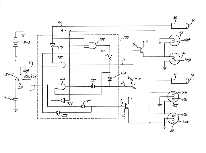
Figure 5 is an electrical circuit diagram
illustrating a preferred embodiment of implementing the
present invention. In that diagram, four headlamps 20,
22, 40 and 42 are selectively energized by an electrical
energy source (Battery B-2) through current drivers DL,
DM or DH, via a control circuit 100. The headlamps
40 and 42 are designated as containing only the high-beam
filaments; and the lamps 20 and 22 are shown as each
containing both low-beam and mid-beam filaments. Of
course, other configurations such as arc lamps or
- ~29~
-- 7 --
separate lamps For high, mid and low beams could also be
controlled in a manner using principals similar to those
disclosed herein.
In Figure 5, a high-beam sensor 30, with a lens
34, is shown and is assumed to be a conventional
high-beam sensor which detects light radiation forward of
the vehicle in a wide range that is at least as great as
the high-beam pattern projection area. In any event the
range of light detection of the sensor 30 overlaps the
mid-beam pattern projection area. The detection of
oncoming vehicle headlamps within the sensing area of
high~beam sensor 30 is provided as a voltage signal on
line A which is also connected to control circuit 100.
A mid-beam sensor 10 may be either of the
sensors previously discussed with regard to-Figures 3 & 4
and is configured to only sense light present in the
mid-beam projection area and produced by oncoming
vehicles within that limited detection area. Upon
detecting light, th~ sensor 10 provides a voltage output
on line B which is connected to the control circuit 100.
A battery B-l is shown as providing logic level
energy to the control circuit 100 via a headlamp switch
SW-l. The headlamp switch SW-l is shown as having three
manually selected switch position settings including
"Off", "~id/Low" and "High".
The control circuit 100 contains various logic
elements configured to provide output signals on the L, M
or H lines to corresponding current driver devices DL,
DM or DH in response to the manually set position of
SW-l and the ON or OFF state of sensors 10 and 30 when
the light levels detected by those sensors are above
predetermined thresholds sufficient to trigger associated
logic elements~
9~
The following Tru'ch Table reflects the function
of the control circuit 100 based upon the variables of
the setting of switch SW-1, the state of high-beam sensor
30 and the state of mid-beam sensor 10.
TRUTH TABLE
SW-l HI-SENSOR 30 MID-SENSOR 10 LIGHTS ON
10 HXGH OFF OFF HIGH/MID/LOW
HIGH ON OFF MID/LOW
H I GH ON ON LOW
MID/LOW - OFF MID/LOW
MID~LOW - ON LOW
In the first instance when the switch SW-l is
set to its High position, the vehicle operator expects
the ~ilaments in high-beam lamps 40 and 42 to be
energized along with the mid-beam filaments and low-beam
filaments in lamps 20 and 22, to provide ma~imum light
output from the vehicle headlighting system. If no
oncoming vehicles are sensed by either the high-beam
sensor 30 or the mid-beam sensor 10, the AND gate 102
receives a relatively high (logic "l") level on line C
and a relatively high ~logic "l") level from inverter
110. The AND gate 102 therefore outputs a relatively
high (logic "l") level on line H to bias the current
driver DH ON. With driver DH in an ON (conducting
state) the high-beam filaments of headlamps 40 and 42 are
energized. Likewise, a direct connection on line C
through diode 126 is made to bias the low-beam current
driver DL ON. With the current driver DL in its ON
state, the low-beam filaments in lamps 20 and 22 are
thereby energized. The absence of detected light by both
high-beam sensor 30 and mid-beam sensor 10 (logic "0")
~,9~
causes the output of AND gate 106 to be at a lor~7 level
(logic "0"). The output of AND gate 106 is inverted to a
relatively high (logic "1") level by inverter 116. The
output of inverter 116 (logic "1") is passed by diode 124
and causes the current driver DM to be biased ON. With
current driver DM in an ON state, the mid-beam
filaments in lamps 20 and 22 are also energized.
In the second instance, with the switch 5W-l
still set in the High position, an assumption is made
that the high-beam sensor 30 detects an oncoming vehicle
and the mid-beam sensor 10 does not indicate such a
detection. In that case, the change in signal on line A
does not affect the relatively low (logic "0") output
state of AND gate 106 and the mid-beam current driver
DM continues to be biased ON. However, the-inverter
110 inverts the relatively high (logic "1") signal from
sensor 30 to provide a relatively low (logic "0") output
signal to an input terminal of AND gate 102. That
combination of input signals to AND gate 102 causes the
output of AND gate 102 to be switched to a relatively low
(logic "0") signal. That low signal is carried by line H
to thereby bias the current driver DH to an OFF state.
With current driver DH in an OFF state, the high-beam
filaments in lamps 40 and 4~ are deenergized. The
high-beams remain deenergized until the sensor 30 ceases
to detect the presence of oncoming vehicle lamps in its
field of view.
In the third instance, where the mid-beam sensor
10 also detects the presence of oncoming vehicle
headlamps within its mid-beam pattern projection area
field of view, both the sensor 10 and the sensor 30
provide relatiYely high (logic "1") signal levels on
lines A and B. This change from the preceding instance
will cause the AND gate 106 to change state and provide a
relatively high (logic "1") level output, since all three
o~
- 10 -
input levels are at a relatively high (logic "1"~ state.
The high (logic "1") output level of 106 is inverted by
inverter 11~ to a relatively low (logic "0") level which
biases the driver DM to its OFF state. In that
instance, the mid-beam filaments in lamps 20 and 22 are
also extinguished, leaving only the low-beam filaments
energized. The mid-beam filaments remain extinguished
until the detector 10 no long senses the presence of
oncoming vehicle headlamps in its field of view.
In the fourth instance, where the switch SW-l is
manually set to the Mid/Low position, the high-beam
filaments in lamps 40 and 42 are not energized and
detection of oncoming headlamps by the high-~eam sensor
30 have no efect on the circuit. However, assuming that
no oncoming headlamps are detected by the mid-beam sensor
10, all three inputs to the AND gate 104 are at a
relatively high (logic "1") level and the output of the
AND gate 104 is at a relatively high (logic "1") level.
This high level output of AND gate 104 is communicated
through diode 122 to bias the current driver DM to an
ON state and thereby cause the mid-beam filaments in
lamps 20 and 22 to be energized. The low-beam filaments
in lamps 20 and 22 are maintained in an energized
condition by the current driver DL that is biased to
its ON state via diode 128 and switch SW-l.
In the event the mid-beam sensor 10 detects the
presence of oncoming headlamps within its limited field
of view, the voltage signal produced on line B is
inverted by inverter 114 to provide a relatively low
(logic "0") level input to the AND gate 104.
Consequently, the A~D gate 104 switches to a relatively
low output state and the current driver DM is biased to
its OFF state, thereby extinguishing the mid-beam
filaments and leaving only the low-beam filaments to be
; 35 energized.
)8
It makes previously proposed "tri-bearn"
headlighting systems more acceptable since it can be seen
from the foregoing description that the present invention
provides an automated system for down-switching beam
patterns to avoid producing glare in the eyes of drivers
of oncoming vehicles.
It will be apparent that many modifications and
variations may be implemented without departing from tAe
scope of the novel concept of this inYention. Therefore,
it is intended by the appended claims to cover all such
modifications and variations which fall within the true
spirit and scope of the invention.