Note: Descriptions are shown in the official language in which they were submitted.
Case 2986
-- 1 --
FAULT CURRENT LIMITER FOR DC MOTOR DRIVE SYSTE~
Backaround of the Invention
The present invention relates to a circuit
for limiting the regenerative fault currents developed
during inversion operation of a drive system for a
direct current motor.
It is common practice to operate direct
current motors in a forward motoring mode of operation
and a reverse inversion mode of operation. For
example, in operating a mine hoist, motoring current is
supplied to the motor to lift a payload up from the
mine while the motor is operated in a reverse inversion
mode to lower a payload into the mine.
During operation of the drive system in the
inversion mode, the motor acts like a generator to put
energy back into the power supply which is an AC line
voltage connected through an AC to DC converter across
the armature terminals of the motor. When operation in
the inversion mode, the drive system is prone to
regenerative currents or inversion fault currents which
have been known to damage various components used in
the drive system including the mechanical drive train.
These inversion fault currents can be caused by a
number of abnormal conditions such as, for example, a
dip in the AC line voltage, a commutation failure in
the converter driving the motor, or a short circuit
,
``` ~29~6
Case 2986
-- 2 --
condition associated with the motor.
In order to safeguard against inversion fault
currents, transformers connected between the AC line
and the power converter have been designed with a
voltage margin above that of the operating voltage of
the motor. This however adversely affects the power
factor and increases the VAR demand from the AC line.
It is also known to discharge the invarsion
or regenerative currents by connecting a discharge
resistor at all times across the output of the supply.
However, this practice results in wasted power.
Further, direct current contactors and interlock
networks to connect the discharge resistor across the
load when required have been used to protect the motor
and circuitry. This solution has proven costly due to
the cost of the high speed breaker used. In Canadian
Patent 830,070 issued December 16, 1969 to Krajewski
there is disclosed an energy dissipating circuit that
connects a discharge resistor across the output of the
supply when the regenerative current exceeds a
predetermined amount. The resistor is switched into
circuit by the use of a thyristor whose gate electrode
senses a voltage rise above an acceptable level.
Summary of the Present Invention
It is an object of the present invention to
provide a means for limiting the regenerative or
inversion fault current in a direct current motor drive
system without effecting the supply of motoring current
to the motor.
It is another object of the present invention
to provide a means for limiting the inversion fault
current associated with a direct current motor drive
system whereby the risk of damage to the components of
the motor drive system from excessive regenerative
currents is diminished.
It is another object of the present invention
~,~9~
Case 2986
-- 3
to provide a drive system that utilizes a transformer
requiring a reduced safety margin and reduced power
consumption.
In accordance with one aspect of the present
invention there is provided a direct current motor
drive system comprising a direct current motor operable
in a forward motoring mode receiving current from a
power source and in a reverse inversion mode providing
inversion current to the power source. The drive
system includes converter means for controlling motor
operation. The converter means converts alternating
current, received from the power source, to direct
current and supplies direct current across terminals of
the motor when operating in the forward motoring mode.
The drive system comprises inversion fault current
limiting means for limiting inversion fault currents
associated with motor operation in the reverse
inversion mode without effecting the supply of current
to the motor in the forward motoring mode. The
inversion fault current limiting means is electrically
connected in series between the converter means and one
armature terminal of the motor. The inversion fault
limiting means includes diode switch means connected in
parallel with resistance means. The diode switch means
conducts during the forward motoring mode to permit the
flow of direct current therethrough from the converter
means to the motor. The diode switch means does not
conduct when the motor is operating in the reverse
inversion mode so as to direct inversion current
through the resistance means and thereby limit the flow
of inversion fault currents.
It should be understood that the value of the
resistance means can be chosen so as to safely limit
the flow of inversion fault current through the motor
and other components of the drive system circuitry.
By using the limiting current resistor in the
o~
Case 2986
manner described, the use a high speed contactor across
the armature is not needed. The resistor by limiting
the inversion fault current enhances the longevity of
the drive electrical circuitry and reduces the torque
fault levels to within acceptable tolerances of the
mechanical drive train. By reducing the inversion
fault current levels, the drive system of the present
invention effectively reduces the margin required to be
built into the transformer connecting the converter
lo with the AC power which reduces the power consumption
of the drive system.
In one preferred embodiment that the
converter means is bi-dir~ctional operable to control
the supply of current to and from the motor
respectively during the forward motoring mode and
reverse inversion mode. In this embodiment the diode
switch means includes a diode having its anode
electrode connected to the converter means and its
cathode electrode connected to the one terminal of the
motor. The motor has a field winding associated with
the motor and a uni-directional converter means
connected to control the current to the field winding.
In another preferred embodiment the converter
means is uni-directional operable to control the supply
of current to the motor in the forward motoring mode.
The drive system further includes a field winding
associated with the motor and a bi-directional
converter means connected to control the current to the
field winding and control the mode of operation of the
motor. The diode switch means comprises a thyristor
connected between the converter means and one terminal
of the motor. The thyristor has its yate terminal
connected to gating logic which controls the conduction
of the thyristor during switching of the motor between
the forward motoring mode and the reverse inversion
mode.
Case 2~86
- 5 -
Brie~ Description of the Drawin~
For a better understanding of the nature and
objects of the present invention, reference may be had
by way of example to the accompanying diagrammatic
drawing in which:
Figure 1 is a schematic representation of a
motor drive system incorporating the inversion fault
current limiting means of the present invention where
the drive system includes a bi-directional converter in
circuit with the armature winding of the motor; and
Figure 2 is a schematic representation of a
motor drive system incorporating the inversion fault
current limiting means of the present invention where
the drive system includes a uni-directional converter
in circuit with the armature windiny of the motor and a
bi~directional converter in circuit with the field
winding of the motor.
Detailed Description of the Present Invention
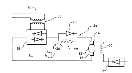
Referring to Figure 1 there is shown one
pre~erred drive system 10 for a direct current
motor 12. Current is supplied to the motor 12 across
its armature terminals 14 and 16.
Direct current is supplied to and taken from
the motor terminals by a bi-directional converter 18.
converter 18 comprises any suitable thyristor
controlled firing circuit that is capable of converting
alternating current into direct current during the
motoring mode of operation of the motor 12 and converts
the direct current to alternating current during the
inversion mode of operation of the motor and drive
system. The converter 18 is connected to AC power
lines 20 through transformer 22.
Connected in series electrical relation
between the terminal 14 of motor 12 and the
converter 18 is an inversion fault current limiting
means 24. The fault current limiting means includes
'38~
Case 2986
-- 6 --
diode means 26 connected in parallel with resistance
means 28. The diode means 26 has its anode electrode
connected to the converter means 18 and its cathode
electrode connected to the positive terminal 14 of the
motor 12.
While motor speed and direction is controlled
by the converter 18, the motor speed is also controlled
by excitation of the motor field winding 30 through a
uni-directional converter 32.
During motor operation in the forward
motoring mode of operation, current, moving in the
direction shown by arrow 34, is supplied to the
motor 12 from the convertor 18. This current passes
through diode 26 which conducts during forward motoring
operation. Virtually no current passes through
resistor 28 at this time. When the drive system is to
operate in the reverse inversion mode of operation,
current will flow in the direction indicated by
arrow 36. Consequently, diode 26 is not conducting and
current flows through limiting restistor 28.
Resistor 28 is chosen so that its resistance value
sufficiently limits the flow of regenerative or
inversion fault currents therethrough and thus protects
the motor and converter components of the drive system
from sudden excessive fault currents.
Referring to Figure 2 there is shown another
preferred drive system 100 for a direct current
motor 120. Current is supplied to the motor 120 across
its armature terminals 1~0 and 160.
Direct current is supplied to the motor
terminals by a uni-directional converter 180.
Converter 180 comprises any suitable thyristor
controlled firing circuit that is capable of converting
alternating current into direct current during the
motoring mode of operation of the motor 12. The
converter 180 is connected to AC power lines 200
38~
Case 2986
-- 7 --
through transformer 220.
Connected in series electrical relation
between the terminal 140 of motor 120 and the
converter 180 is an inversion fault current limiting
means 240. The fault current limiting means includes
thyristor or SCR 260 connected in parallel with
resistance means 2800 The thyristor 260 has its anode
electrode connected to the converter means 180 and its
cathode electrode connected to the positive
terminal 140 of the motor 120. The thyristor 260 has a
gate electrode 265 connected to gate logic
circuitry 268. Motor speed and direc~ion is controlled
by the bi-directional converter 320 connected to the
field winding 300 of the motor 120.
During motor operation in the forward
motoring mode of operation, current, moving in the
direction shown by arrow 340, is supplied to the
motor 120 from the convertor 180. This current passes
through conducting thyristor 260 since the gate
electrode 265 will be enabled by the logic
circuitry 268. Virtually no current passes through
resistor 280 at this time. When the drive system is to
operate in the reverse invers.ion mode of operation,
current will flow in the direction indicated by
arrow 360 due to a change in the direction of the field
current supplied to the field winding 300 by
converter 320. This change in direction of current is
sensed by the logic circuitry 268 which inhibits the
gate electrode 265 of thyristor 260 resulting in the
thyristor not conducting. Consequently, diode 260 is
not conducting and current flows through limiting
restistor 280.