Note: Descriptions are shown in the official language in which they were submitted.
~Z~454
APPARATUS YOR DISPE~SING TICKETS
FIELn OF THE INVENTION
... . . . . _ _
The present invention relates generally to ticket
dispensing apparatus and more particularly relates to
apparatus for dispensing lottery tickets.
BACKGROUND OF TIIE INVENTION
_ .
State-sponsored lotteries are now a popular and
accepted method of ~enerating revenue in place of taxes.
One popular form of the lotteries is the Lotto-type game
where the player selects his own numbers, for e~:ample by
filling out a computer card, and receives a lottery tickct
which has been printed with his selected numbers. ~ drawing
is then held at ~ later time to determine the winning
numbers. Another popular form of lottery uses tlle so-called
instant lottery tickets, on which winning or non-winning
combinations are preprinted before distribution so that no
later drawing is necessary and the player knows immediately
after purchasing his ticket whether or not he has won.
The usual system ~or distributing Lotto-type
lottery tickets includes a large number of ticket-dispensing
remote units located at drug stores, supermar~ets, liquor
stores and the like. Each unit is independent and is
operated by the store owner, who customarily receives a
portion of the ticket prico for each lottery ticket sold.
The usual system ~or distributing instant lottery tickets,
on the other hand, is entirely clerical, with the tickets
being stored in a drawer and counted out by hand . The s tore
owner typically is responsible ~or keeping track of the
1290454 PAT~NT
332-2]30
number of tickets sold, making redemption payments up to a
certain amount for certain types of winning tickets and for
providing such sales and pay-out information to the state.
The state in turn calculates the money due from or owing to
the store owner and sends an invoice and/or moncy payment.
Given the very large number of stores which now sell lottery
tickets, it would be highly desirable to simp]ify the
accounting proccdure so as to avoid any mistakes or
improprieties by the store owncr and to as.qllre proper and
prompt payment of all monies due. It would also be valuable
to the state to know on a daily ~asis whetller each store
owner has a sufficient supply of tickets, as well as how
much money i5 due that day.
Another consideration in lottexy ticket
distribution is the speed witll which the lottery tickets may
be sold~ It is a frequent o-currence in large cities for
long lines of ticket buyers to form at lunch time or after
work in order to buy tickets. ~s mentioned above, the
ticket sc]lor has conven~ionally ha~ to c~unt: ollt and h;ll-d
instant lottery tickets himself to the customers~ It wnuld
be highly advantageous and to have A ticket-dispensinq unit
which would itself dispense instant or other lottery ticl:et~
at an outlet where they are easily accessi~le to the
customer.
Sill anotller co1lsideration in a lottery tic~et-
dispensing unit i9 security. Particularly ~hen instant
tickets are being dispensed, the unsold tickets should l)c
locked up in the unit or drawer to prevent their theft.
Since the unit or drawer must be periodically opened to
allow a new supply of lottery tickets to be inserted, it is
,, . . ~ .
12~)454
PATENT
332-2130
important to keep track of when and how often ~he tickets
are replaced. In additinn, it may be necessary for security
reasons to keep track of which lottery tickets were sold
from which location, both to detect and prcvent for~erie~
and unauthorized sales and to assist the customers in making
complaints, suggestions or the like.
Particularly when a large number of tickets are
stored within the dispensing unit, it is an advantageous
feature in the present invention to provide the tic~cts in a
fan-fold stream so that they may be rapi~ly fed out from
storage without the risk of double feeding present when
separated tickets are stored. There is as yet no
standar~ization in the size of the tickets, which come ;n
various widths and lengths. It would be highly advant~eous
to provide a dispensing mecha,nism within the dispensincJ unit
to separate the tickets from the straam while ensuring that
the separation of the tickets occurs onl~ at the joindor
line therebetween, since again for security reasons
generally only complete tickets are redeemable.
OBJECTS AND SUMMA~Y nF THE INVr.NTION
Accordingly, it is an object of the present invention
to provide an apparatus fox dispensing lottery tickets which
addresses these factors.
Specific embodiments of the present invention may
pxovide for one or more of the following features:
54
Automatic transmission of sales data for a number of
different ticket-dispensing units to a central data processor
for system wide accounting evaluation.
Automatic calculation of accounting information at
each appropriate ticket-dispensing unit for print-out thereat.
Communication between the central data processor and
the dispensing units being periodically ~stablished so as to
transfer the sales data during limited intervals of time,
thereby avoiding the need for a permanent communication link.
Accurate and current accounting of the ticket supply
and monies due both to a controlling authority and to the sales
agents.
A control panel mounted at the front and accessible
to the sales agent and a dispensing outlet at the back and
accessible to the customer so as to speed up the dispensing of
tickets.
Storage of tickets in a fan-fold stream in which the
tickets are separable from each other along lines of weakness.
The tickets may be separable by bursting the lines of weakness
to provide an automatic mechanical alignment of the tickets.
Detection and recordal of each access to a ticket
storage area.
In accordance wikh one aspect of the invention there
is provided apparatus for dispensing lottery tickets including
a box-like module having opposed front and back surfaces, ticket
storage means within the module for storing a plurality of
tickets and control panel means mounted at the front surface of
the module and actuatable for initiating dispensing of a lottery
ticket. A dispensing outlet is manually accessible at the back
surface of the module for receiving a dispensed lottery ticket
from the ticket storage means. The apparatus also includes
ticket dispensing means responsive to the control panel means
for dispensing a lottery ticket from the ticket storage means
to the dispensing outlet, whereby the dispensed lottery ticket
may be manually removed from the apparatus.
~L;29045~
In accordance with another aspect of the invention
there is provided apparatus for dispensing tickets such as
lottery tickets including ticket storage means including ticket
storage means for storing a plurality of tickets connected in
a fan-fold stream headed by a leading ticket, in which the
tickets are separable from one another along lines o~ weakness.
Transport means i5 provided for feeding the string of tickets
from the ticket storage means along a predetermined dispensing
path and separating means is provided for separating the leading
ticket from the stream of tickets along a leading line of
weakness between the leading ticket and a next following ticket
by bursting the tickets apart along the leading line. Manually
accessible outlet means is provided for receiving the separated
ticket. The separating means includes a dull-edged bursting
blade movably mounted adjacent a predetermined bursting position
along said path, holding means for holding the stream of tickets
against substantial deflection from the path at said bursting
position, and bursting blade drive means for bringing the
bursting blade into bursting contact with the stream of tickets
at the bursting position to burst the leading ticket from the
next following ticket. The separation means includes feed
alignment means for controlling the transport means to bring the
leading line of weakness to the bursting position. The alignment
means includes sensor means for detecting a present position of
the leading ticket relative to the bursting position,
determining means for determining a transport direction and a
displacement distance necessa.ry to bring the leading line of
weakness to the bwrsting position, and transport control means
for generating a transport signal indicative of the transport
direction and displacement distance, the transport means being
responsive to the transport control signal for transporting the
stream of tickets in the transport direction by the displacement
distance.
The transport control means may be responsive to
transportation o~ the stream of tickets by a predetermined
~L~904~
incremental distance to generate a transport pulse. ~he
determining means calculates an integral member substantially
equal to the displacement distance divided by the incremental
distance and the transport control means permits transpor~ by
the transport means during generation of said number of
transport pulses to bring the leading line of weakness to the
bursting position.
A further aspect of the invention provides a ticket
dispensing machine for dispensing tickets directly -to the
purchaser thereof. The dispenser includes the combination of
housing means for storing a strip of tickets to be dispense,
said housing means having an outlet open~ng accessible to the
purchaser of tickets from said machine, means operable for
ordering a plurality of tickets in a single batch, means for
separating each of said tickets from said strip, dispensing
means for dispensing tickets through said outlet opening, and
control means for causing each ticket in said batch to be
separated and dispensed separately from the other tickets in
said batch regardless of the number of tickets in said batch.
A further aspect of the invention provides apparatus
for dispensing tickets from a strip of tickets delineated from
one another by lines along which the material of the strip is
weakened. The apparatus includes, in combination, means for
moving said strip towards a dispensing position, a separation
member, mans for holding said strip adjacent one line along
which said strip is to be separated, and causing said strip to
bend along said one line at said dispensing position to
facilitate tearing of said strip by engagement with said
separator member along said one line while said strip is bent,
and including drive means for creating motion of said separator
member and said strip relative to one another in a direction
transverse to the strip, with said member in contact with and
deflecting said strip to bend said strip along said one line and
burst said tickets apart along said one line.
.,
,. .:,~
1.2~3~4S4
A further aspect of the invention provides apparatus
for dispensing tickets from a strip of tickets delineated from
one another by lines along which the material of the strip is
weakened. The apparatus includes, in combination, means for
moving said strip ~owards a dispensing position, means for
holding said strip adjacent one line along which said strip is
to be separated, and bending said strip along said line to
facilitate tearing of said strip along said one line, including
separation means having a separator member and drive means for
creating motion of said separator member and said strip relative
to one another in a direction transverse to the strip, with said
member in contact with the deflecting said strip to bend said
strip along said one line and burst said tickets apart along
said one line, and including means for causing said separator
member to break through said strip in one locale and then
transverse the strip along said line.
Accordingly, a still further aspect of the invention
there is provide a dispenser for dispensing tickets from a strip
of tickets printed in a strip with the individual tickets being
delineated from one another by lines of weakness. ~he dispenser
includes moving means for moving a strip by predetermined
distance to a position to which one of the lines is separated
is near a separation location at which ad;acent tickets are
separated from one another. The moving means includes drive
means for moving the strip by a predetermined distance and
position detecting means for detecting the distance actually
moved by the strip and producing an output signal to control the
drive means to drive the strip until the output signal indicates
that the strip actually has moved by the predetermined distance
to dispense one of the tickets, and to control means for
severing a ticket from the strip.
Alternatively, the detecting means may include a
rotary code wheel drivably coupled to the strip, and the
dispenser may include means for detecting the incremental
movements of the wheel and converting them into actual signals
~L29~4~;~
and includin~ an idler roller driven by the motion of the strip
and drivably coupled to a ~haft on which the code wheel i9
mounted.
In a further alternative, the dispenser may include
a front edge detector to detect the front edge of a ticket to
be separated, memory means or storing information corresponding
to the distance the strip is to be driven after its front edge
is detected and before separation, means for comparing the
stored information with the output of the position detecting
means, and for actuating separating means when a predetermined
comparison condition is reached, including separator means at
said separation location, means for causing the dispenser to
issue a plurality of tickets, the number of which corresponds
to an order for a batch of tickets, and means for operating the
separator means to separate each of said tickets rom the others
in the batch.
In order that the invention made be more clearly
understood reference will now be made to the accompanying
drawings which illustrate a particular preferred embodiment of
the invention by way of example.
(
~ 7(a)
--- 9 2~
PATRNT
332-2130
B~IEF DESCRIPTION OF TilE DRAWINGS
Fig. 1 is a schematic diagram illustratlng a
prefPrred embodiment of the system for distributing lottery
tickets according tD the present invention;
Fig. 2A is an exemp:Lary daily sales report
produced by the present inven~ion;
Fig. 2B is an exemplary weekly sales report
produced by the system according to the pres~n~ invention;
Fig. 2C is an exemplary weekly invoice produced by
the system according to the present invention;
Fig. 2D is an exemplary current sales rcport
produced by the system according to the present lnvention;
Fig. 3 is a front elevational view of the
preferred embodiment of a tickat-dispensing unit according
to the present invention;
Fig. 4 is a partial rear elevational view of the
embodiment of Fig. 3;
Fig. 5 is a schematic view of the ticket trans~ort
mechanism of the prcferred embodiment;
Fig. 6 is a schematic view of a leading edgc
ticket sensor of the prefexred embodiment;
Fig. 7 is a partial elevational mechanical view of
the ticket drive and burster assemb]y of the preferred
embodiment;
Fig. 8A is a diagrammatic illustration for
explaining the alignment process of the ticket drive and
burster assembly of Fig. 7;
FigO 8s is a second diagrammatic illustration ror
explaining the alignment process of Fig~ 8A;
--8--
~9 ~4~4 PATENT
332-2130
Fig. 9 is nn elevakional mechanical view of ~n
lmprinter assembly of the preferred embodiment;
Fig 10 is a functional block diagram of the
prcferred embodiment;
Fig. 11 is an eleckronic block diagram
corresponding to Fig. 10; and
Fig. 12 is a f].owchart illustrating fundamental
operations o the preferred embodiment.
DETAILED DESCRIPTION OF T~IE pREFEr~RED EMBODII~I~Nq`
Referring now to the drawings, and initially to
Fig. 1 thereof, a system 10 for dispensing lottery tickets
includes a central computer 12 and three remote ticket-
dispensing units 14, 16 and 18. Although the illustrated
embodiment includes three such ticket-dispensing units, it
will be understood that any number of units may be employed,
and indeed it is anticipated that a very large number of
units will be employed in a state-wide or nation-wide
lottery system. For the purposes of the present
description, the lottery will be assumed to be a state-wide
lottery run by a state authority. Ilowever, the present
invention is applicable to other lotteries .such as
nation-wide or city-wide lotteries.
Each unik 14, 16, 18 is located at a separate
location across the state in, for example, grocery stores,
liquor stores and the like, and functions completel.y
independently of the other units. Each remote unit 14, 16,
1B is independently operated by a sales agent or vcnclor,
generally the store owner who s~lls the lottery tickets as
part of his business, receiving a percentage of the purchase
1~9~454 PATEN~
332-2130
price of each ticket sold from the state agency which runs
the lottery. ~lowever, each unit 14, 16, 1~ is independently
and selectively placeable in communication with central
computer 12 through a respective modem 20, 22, and 24. ~acl
modem 20, 22, 24 i8 advantageously positioned within its
associated unit 14, 16, 18 at the particular location, or
may be adjacent thereto. Advantageously, each of the modems
20, 22 and 24 is a dial-up modem which is actuated by its
own conventional touch-tone telephone circuitry ~Fig. ]O) to
access a telephone line between modem 20, 22, 24 and central
computer 12.
In accordance with an aspect of the present
invention, each unit 14, 16, 18 independently records each
ticket sale thereat and stores sales data indicating at
least the number of tickets sold and, more generally, the
numbers, types and prices of different tic~ets sold. ~t
periodic intervals, such as several times a day, once eacl
day or once each week, each unit 14, 16, 1~ is placed in
communication with central computcr 12 by central computer
12 dialing up the respective modem 20, 22, 29. Once
temporary communication is esta~lished, tho rcspcctivc s.les
data is transmitted from the units 1~, 16, 18 to centr~l
computer 12. Central computcr 12 can operate as a celltlnal
data processor to perform all the necessary accounting
functions, including determining such information as the
volume of sales and money due to or ~rom each sales agent at
his particular location. In addition, each uni-t 14, 1~
itsel performs accounting Eunctions on its own sales data.
The transfer of the sales information from each unit
-10-
~9 ~ 4~4 PATENT
` 332-2130
14, 16, 18 takes only a very short period o~ time, usually
on the order of seconds, and so the tlme during which moflems
20, 22 and 24 respectively access the telephone lines is
very brief, resulting in sign.ificant cost savings over
systems which may require a continuous or extende~
connection over the phone lines to a central control.
Thus, in accordance with the present invention, it
is unnecessary for the sales agent to prepare any paperwor~
to keep track of ticket sales, to make any accounting of the
sales or to otherwise report SUCIl sales to the state
authority. Similarly, it is unnecessary for the state
authority to physically collect such sales data from the
numerous individual sales agents. Instead, central computer
12 at the appropriate time ~everal times a day, each day or
week simply actuates each modem 20, 22, 24 by dialing the
telephone number assigned thereto, as is conventional, and
the sales data is transmitted from the respective unit 14,
16, 18 to central computer 12 without furtller interventi.on
or action by either the agent or the state authority. This
insures that sales data is æent promptly to central computer
12 without the rlsk o tampering and without possibl.e delays
or losses through the mails. Furthermore, both the stnte
authority using central computer 12 and the sales aqent
using his unit 14 have access to a current, up to the minutc
sales accounting of how many tickets have been sold and how
much money is due. The state authority can then know each
sales agent's current stack of tickets and can resupply him
before the stock runs out, which is a valuable commerc.inl
advantage for stabilizing cash flow, and can also
efficiently close out a particul.ar game. Central computer
PATENT
332-2130
12 may account for each unit 14, 16 and lR separately and
may also combine the sales data from all the units so as to
provide a state-~tide summary.
Of course, the sales data advantageously includes
more data than just the number of tickets sold. It shou1d
include, for example, an agent number idcnt.ifying the sale.s
agent, a machine number identifying the particular remote
unit, the sales agent's commission, frequently in the form
of the percentage of the sales price, winning ticket values
which the sales agent has redeemed, and the ticket purchase
price, frequently in one dollar increments. Other sales
data which may be automatically recorded by units 14, lG, 18
may be transmitted Prom an electronic cash re~ister or
entered by the agent on a control panel, as discussed belo~.
This sales data, plus other types of sales data related to
the particular application, may also be included and
transmitted to central computer 12.
Remote units 14, 16, 18 are responsive to
acounting data calculated fr~m the respective sales data
stored therein to print a report ~or the sales agent,
summarizing the accounting results. The format o the~e
reports may vary with the particular lottery system use~1,
but may advantageously take the Porm of the exemp]ary
reports illustrated in Figs. 2A-D. Fig. 2A il].ustratcs a
daily sales report, Fig. 2B illustrates a wcekly sales
report, Fig. 2C illustrates a weekly invoice and Fig. 2D
illustrates a current sales report. As sl)own, cacll rcpol-t
is individualized to the particu].ar unit l~, 16, 18.
-12-
45~L
PATENT
332-2130
Since each unit 14, 16, 18 can record both the
number of tickets sold At the particular location and also
the amount of money paid by Lhe sales agent in redeeming
certain types of winning tickets, the reports are then a
through reflection of the sales and redemption activity and
may completely replace the use of invoic~s between th~ state
authority and individual sales agents.
Central compueter 12 can be programmed dial up any
modem 20, 22, 24 in off hours to interrogate it and get an
up to the minute accounting, which is an advantage in
increasing cash flow. Modems ~0, 22, 24 may alternative]y
include a timer mechanism prvgrammed 50 as to automatically
dial up central computer 12 at preselected intervals to
ensure that the sales data is regularly transmitted. For
security reasons, the sales agent advantageously should not
have the responsibility for connecting central computer 12
and modems 20, 22, 24.
Central computer 12 is operative to send messa~e
data indicativc of mesSatJes to units 14, lfi, 18. Tht?st?
messages may be individu~lized for the respective units 14,
16, 18, for example stating whether the particular sales
agent is behind in his payments. ~lternatively, central
computer 12 may send the same message to all units 14, 16
and 18. Such a message may be, for example, advertising
announcing a new game or a special jackpot. These messages
may be intended either or the agent or for the customers
and, as discussed below, an advantageous embotliment of llni t
14, 16, 18 includes separate message ~isplay sections for
the two types of messages.
~2~4~
PATENT
332-2130
Referring now to Figs. 3 and 4, a preEerred
embodiment of unit 14 will now be described. It will be
understood that units 14, 16, 18 and all others within thc
lottery ticket distributing system are intende~l to be
identical. Therefore, while a detailed description is
given only with respect to unit 14, it will be understood
that this description applies equally well to all other
units within the system.
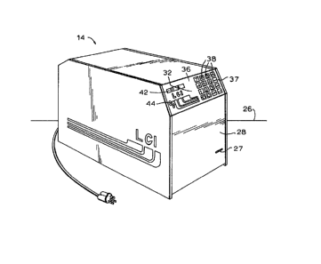
Referring first to Fig. 3, unit 14 is constructed
as a box-like module advantageously designed to rest upon
the surface of a counter 26 or the like. Unit 14 includes a
front surface 28 which, when unit 14 is positioned on
counter 26 and is in operation, is intended to face tlle
sales agent or vendor standing behind counter 26. A
corresponding, opposed back surface 30 of unit 14 is
intended to face the customers when unit 14 is in operation.
In accordance with an important aspect of the present
invention, a control panel 32 including all neccssary
agent-operated controls is mounted at front surface 28,
while a dispensing outlet 34 is manually accessible at back
surface 30 by the customers. Thus, the sales aqent may
quickly and eficiently enter a sales command, for example
in the form of the number oE tickets to be dispensed, on
control panel 34 at front surface 28 while the tickets arc
automatically presented in response to the command in
dispensing outlet 32 at ~ack surface 30. This structure
eliminates the need for the sales agent to physically
~290454 PATENT
332-2130
receive the lottery tic~ets from unlt 14 and to personally
hand the lottery tickets to the c,ustomer, as is done in
conventional lottery tic~et dispensers.
As illustrated in Fig. 3, control panel 32 is
mounted a~ front sur~ac~ 32 on an upper portion 36 therc~.
Upper portion 36 may be provided at an inclined angle
relative to front surface 28 for ergonomic reasons to permit
comfortable access to control. parlel 32, but the angle o~
inclination is limited so tha.t control panel 32 remains in
substantially opposed relation to back surface 30. The
angle of inclination is limited not only so that control
panel 32 may be easily viewed and operated by the sales
agent, but also so that it will be substantially blockecl
from view by any customer standing in front of counter 2G
and facing back surface 30. This prevents any interference
by the customer in reaching towards c,ontrol pane]. 32 in an
attempt to operate unit 14 in an unauthorized manner.
Control panel 32 includes a ke~pad 37 having a
plurality of push-buttons 38 for entering data and commands
into a control circuit 40 (Fig. lO) within unit 14. Control
unit 40 may be a microprocessor based circuit or
mini~omputer which controls the operation of unit 14 and is
described 1n greater detail ~)elow. Pusll-~uttons 3n incl.tlcle
numerical buttons bearing the digi.ts 0-lO and an entry
2~3C)D~54 PATEMT
332-2130
button for entering the corresponding numbers to control
circuit 40. Push-buttons 3~ further may include a cash
button, a report button, a sign on button, a ticket length
load button, a storage access button and all other buttons
necessary for entering all appropriate data entry and
commands in accordance Wit]l the fllnctions described below.
In particulart when unit 14 has been activated, any number
of tickets from 1 through 999 may be dispensed simply by
depressing th~ appropri~te numerical push-button 38 and the
entry button 38. Thus, if the sales agent depresses thc
numerical push-button 38 bearing the digit "1", a confirming
display will appear on an operator LCD device 42, discusse~l
below, and the sales agent may depr~ss entry button 3~ and a
single lottery ticket will be dispensed and deposited in
dispensing outlet 34 at back surface 30 (Fig. 4). The
customer simply reaches into dispensing outlet 34 to rcmovc
the ticket. Alternatively, if the sales agent depres!3es the
numerical push-button 38 h~aaring the digit "5" and th~n~
entry button 38, remote unit 14 will automatically deposi~
five, separated lottery tickets into dispensing outlet 34.
There is no need for the sales agent either to count out ~he
tickets or to physically receive the tickets and hand them
to the customer. This significantly spee~s up the ticke~
selling process, as the ~sales a~ent may concentrate on
rec~iving money and givin~3 chan~e, a taslc whicll is botll
easier to perform when not handling tickets and more likely
to be accurat~. Each ticket sol~l is countc~, a~v~nta~ sly
in response to operation of the mechani.sm which provides a
separated ticket to dispenslng outlet 34, and the number is
-16-
~ ~0454 PATENT
332-2~30
stored as sales data in memory within control cixcuit 40.
Other sales data, such as the price of the tickets may also
be stored therein. Wllen communication with central computer
12 is established, the sales data is send out from the
memory by control circuit 40 and fcd out over tlle phone linc
to central computer 12.
Control circuit 40 similarly may receive message
data from central computer 12 and stores it in the memory
along with the sales data and the accounting data calculated
therefrom. The report push-button 38 causes a selected one
of the reports illustratcd in Figs. 2A-D to be printed, for
example on a tape by a thermal printer 140 lFig. 10) and
pr~sented at front surface 38 through slot 39. ~s mentioned
above, central computer 12 may send messages to unit 14.
Some of these messages will be intended for the sales agent
and not for customers and so are considered to be control
messages rather than advertising messages. To display these
control messages, a display device, such as a conventional
LCD device 42 i8 provided in control panel 32 on inclincd
surface 36 and adjacent keypad 37. In accordance witll
conventional techniques, central computer 12 can transnlit
message data indicative of these messa~es through modem 20
whenever modem 20 is actuated to transmit sales data ~rom
unit 14 to central computer 12. This down-loading of
message data is achieved without any need to request the
same by the sales agent. The placement of LCD display 42 Gn
inclined surface 36 further shields the control mes~a~e
displayed thereon from the eyes of customers.
Alternatively, the control or other messages may be printed
by thermal printer 140 on the tape and presented throll~h
slot 39.
17-
~9~4~4
PATENT
332-2130
A key 44 is also provided on control panel 3~ for
the purpose o~ controlliny the operating mode of unit 14.
In a locked or of~ mode of operation, unit 14 is disabled
both from receiving commands from control panel 32 and from
communicating with central computer 12 through modem 20. In
a normal mode of operation, unit 14 is enabled to receive
commands entered on control panel 32 and to dispense
tickets, but remains disabled from communication with
central computer 12. In a communication mode of operation,
unit 14 is enabled for receiving commands throuqh control
pan~l 32 and is responsive to modem 20 to permit two-wa~
communication between unit 14 and central computer 12. ~n
the communication mode, unit 14 and modem 20 will answer a
telephone call from central computer 12 or may be actuated
a.q by dialing the telephone circuitry within modem 20 to
place a telephone call to central computer 12 and to
thereafter exchange information. Key 44 has threc different
positions respectively associated with the three different
operating modes of unit 14. Advantageously, key 44 must be
inserked into unit 14 and turned to place unit 14 in either
of the normal or communication modes, and is removeablc ~rom
unit 14 only when it is in the lockcd position ~o p~ace un.it
14 in the loc1ted mode.
A second message display device 46, advantageous]y
an LCD device, is located at back surface 30, advantageollsly
on an upper inclined portion 48 thereof for casy viewing ~y
the customers. When message data from central computer 12
contains advertising data indicative of an advertising
slogan or the like, a corresponding message may be dis~laye(l
on TCn di.s~ay 4fi. Contro] circuit 40 in remotc unit 14
-18-
PATENT
332-2130
distinguishes between the two types of data and selects the
appropriate LCD device 42, 46 or thermal printer 140 for
display.
A highly advantageous aspect of the present
invention is that the lottery tickets within unit 14 are
stored in a fan-old stream headed by a leading ticket and
are no , as in conventional lottery tickets dispensers,
provided in stacks of pre-cut tickets for individual
dispensing. Prior art ticket dispensers which did store the
tickets in pre-cut form had the difficulty that two tickets
could accidently could be dispensed instead of a single
ticket when two tickets within the stack were stuck
together. The present invention completely removes the risk
that t~70 or more tickets may be dispensed in place of a
single ticket first by storing the tickets in a fan-fold
stream and secondly by providing a highly advantageous
ticket separàtion mechanism for separating the leading
ticket rom the stream of tickets. This novel separation
mechanism addxesses and removes a difficulty which arises
when tickets are to be dispensed from a fan-fold stream. In
particular, a most common item fed from a fan-fo~ tre~m i~
the like. Such paper is relatively thin and ~lexible an~l
further has a column of perforations or holes at eikher side
which may be fed into and positively held by a tractor feed
of the printerO Such a feeding mechanism provides automatic
lengthwise and widthwise alignment of the paper as it is fed
through the printer. However, lottery tickets
conventionally do not have such columns of perforations and
indeed are constructed from laminated layers of paper or
--19--
rATE~lT
332-2130
~ardboard so as to be relativ~ly ~tiff. The problem faced
and solved by tlle transport mechanism in accordance with ~he
present invention is how to ensure that each ticket as it
becomes the leading ticket will be separated from tlle ne:;t
following tieket precisely along the joinder line betwcen
the tiekets. In such a fan-fold scheme, a line of wcakness,
for example a perforation line, is provided to define eaci
ticket and to permit folding of the stream of connected
tickets. In the illustrated embodiment shown in Fig. 5,
eaeh fold eontains a single tieket, for clarity of
illustration, but in a preferred embodiment a number of
tickets, for example five, may be provided within each folcl.
Simply to provide a knife edye or cutting blade to slicc
through the stream of tickets is disadvantageous, since such
a knife edge may cut through the stream at any point, such
as in the middle of a ticketr and so a highly precise
alignment device must be provided with such a knife edge to
bring it into precise alignment with the joinder line
between tickets. The pre~etlt invel-tion provi.des a novc].
separation mechanism whi.ch bursts the leading ticket from
the next following ticket along the li.ne of weakness
therebetwe0n, instead of cutting the two tickets apart. Not
only does this inherently reduce the ri.sk of producing only
half a ticket, but also it p:rovides an automatic mechanical
alignment of the tickets to their proper position for
bursting. A separate alignment mechanism is also provided
to adapt the burster mechanism to tickets of differcnt,
selected lengths and cooperates with thc burster mechanism
-20-
~Z~5~
PATENT
33~ 2130
to provide precise, rapid ~eparation of each tic~et from the
stream.
More particularly, an advantageous embodiment o
the ticket transport/scparation system in uni.t 14 is
~chematically illustrated in Pig. 5. A plurality of
indivicdual tickets 49 are connected in a fan-fold stream 50
which is drawn from the top of a stack 51. The tickets 49
are provided by the.state authority in stack 51, which is
compact and easily transportable when including, for
example, 1500 tickets. The illustrated embodiment shows a
single ticket 49 within each fold, but it will he understood
that a greater number of tickets could be providcd within
each fold. Stream of tickets 50 is headed by a ].eacliny
ticket 52 which is connected to a next f~llowing ticket 54
along a line of weakness 56 (Fig. 6) and it will be
understood that each successive following ticket is
separable from its neighbors by similar lines of weakness
56. Stream of tickets 50 is ~ed along a dispensing path 57
from a storage area 58 holding stack Sl within unit 14
towards dispensing outlet 34 and i.s transported along
dispensing path 57 by a transport mechanism including
opposed upper ancl lower feed rol].ers 60, 62 and opposed
upper and lower exit rollers 64, 66. Leading ticket 52 is
separated from next followinc3 ticket 54 by a burster whee].
68 positioned adjacent dispens.ing path 57 at a burstinc~
position 70 therealong. Cor,sequently, upper and lower feed
rollers 60, 62 are driven separately from upper and lower
exit rollers 64, 66 so that upper and lower feed rollers 60,
62 transport stream of tic~ets 50 from storaCJe area 58 up to
~ ~9 [3~54
PATENT
332-2130
bursting po~tion 70, while upper and lowex exit rollers 64,
66 operate as "kick-out" rollers to discharge the separated
leading ticket 52 from dispensing path 57 into dispensing
outlet 34 . A drive motor 72 (Fig. 8) is provided to drive
upper and lower feed rollers 6~1, 62, while a separate
"kick-out" motor 74 is provided to drive upper and lower
exit rollers 64, 66.
When stream of tickets 50 has been transported to
bring the line of weakness 56 between leading ticket 52 and
next following ticket 54 to bursting position 70, burster
wheel 68 is moved into bursting contact therewith in ordcr
to separate leading ticket 52 from next following ticket 54.
As indicated schematically in Fig. 5, burster wheel 68 is
advantageously in the form of a circular burster bl~de
which, in an important.aspect, has a dull, rounded edge
which does not cut stream of t.ickets 50, but rather exerts
pressure ayainst the top of stïeam of tickets 50 in a
direction to deflect it from dispensing path 57. ~Ihen line
of weakness 56 is at bursting position 70, upper antl ]OWCI
exit rollers 64, 66 are gripping a portion of leading ticket
52, while upper and lower eed rollers 60, 62 are similarly
gripping a following portion of stream of tickets 50, with
the result that stream of t:icl;ets 50 is he].d between the two
sets of rollers against substantial deflection from
dispensing path 57. This ellables the bursting force from
bursters 68 to separate the tickets 52, 54. Ilowever, the
grip on stream of tickets 50 by upper an~l lowcr rec~ ro].]~r~;
60, 62 and upper and lower exit rollers 64, 66,
respectively, nevertheless permits a slight deflection o~
-22-
PATENT
332-2130
stream tickets 50 from dispensing path 57 in response to
pressure exerted ~y burster wheel 68. This sliqht
aeflection provides a highly advantageous and novel
alignment system in accordancc w;th the prosont invcntion.
The alignment system operates as follows.
In order for burster wheel 68 tn effectively burst
leading tic~et 54 from stream tickets 50 at line of weakness
56, it must be sufficiently aligned with lines of weakncs.
56 so as to exert pressure almost directl-y thereon.
Clearly, if burster wheel 68 is brought into bursting
contact with leading tickets 54 at a middle portion thereor,
leading kickets 54 will either be torn or bent an~ a1most
certainly will not be properly dispenscd. A separate
alignment mechanism, discussed below, is effective to bring
line of weakness 56 to within at least a predetermined
incremental distance of bursting position 70, but even
within this incremental distance it is still advantageous ~o
have line of weekness 56 precisely aligned with bursting
position 70 for best results. Furthermore, all .systems will
have a certain amount of slippage and tolerance. Ilowever,
in accordance with the present invention, the very action of
burster wheel 68 in combination with upper and lower exit
rollers 64, 66 and upper and lower feed rollers 60, 62
provides a mechanical alignmant to remove any errors within
the incremental distance. Specifically, as i]lustrate~ in
Fig. 8A, the force from burster wheel 68 is exerted at
bursting position 70 along the direction of arrow A. In
Fig. 8A, it is assumed that line of weakness 56 has fallen
short of bursting position 70 by a distance a. Since the
-` 12~ 5af~
PAT~NT
332-2130
~orce ~rom burster wheel 68 is not exeLted directly on line
of weakness 56, line of weakness 56 will not ~mmediately
begin ~o burst apart but instead tickets 52 and 54 will be
deflected slightly from dispensing path 57, as indicated in
a solid line, and will tend to bend first at line of
weakness 56 into a V shaped configuration indica~ed in a
dashed line. Consequently, tickets 52 and 54 will tend to
slip along dispensing path 51 so as to brin~J the low point
of the V-shaped into contact with burster wheel. In Fig.
8A, tickets 52 and 54 will tend to move in the dixection of
arrow B, feedlng forward stream of tickets 50 until line of
weakness 56 is properly aligned with bursting position 70.
Correspondingly, as shown in Fig. 8B, when line of weakness
56 is slightly in advance of bursting position 70 by
distance b, the force of burster wheel 68 will cause tic~ets
52 and 54 to move slightly along the dispensing path in the
direction of arrow C, reverse feedin~ stream of tickets 50
to again bring line of weakness 56 into precise alignment
with bursting position 70. This is an advantage of thc
burster mechanism in accordance with the present invention
which is totally unavailable in any prior systems using a
cutting blade to separate tickets or the like from a stre~am
and represents an important feature of the present
inv~ntion.
It will be clear that if tickets 49 are alway~ of
a predetermined, uniform len~th, the position of burster
wheel 68 alon~ dispensing path 57 could be predetermined and
the mechanical self-alignment action just described could he
sufficient to maintain proper alignment. The system
-24-
~x9~
P~TENT
332-2130
according to the present invention has the adclitional
feature, however, of accepting and dispensin~ tickets of
different lengths and includes an alignment mechanism for
bringing line of weakness 56 '_o within at least a
predetermined incremental dis~,ance of bursting position 70
regardless of the length of~ tickets 49. As illustrated in
Fig. 5, a ticket sensor 76 is positioned along dispensing
path 57 at a sensing position 78 downstream from bursti.ng
position 70 and upstream o upper and lower cxit rollers 64,
66. Ticket sensor 76 operates as a leading edge detector to
detect the leading edge 80 of ].eading ticket 52 (Fig. G)
after the previous leading ticket has been separated and
dispensed by the action of upper and lower exit rol].ers 64,
66 while upper and lower feed rollers 60, 62 are held
stationary. As shown in Fig. 6, ticket sensor 76 may be a
conventional optical sensor havi.ng a U-shaped cavity S2
through which stream o tickets 50 passes to interrupt a
light beam supplied to a light sensor 84. In accordance
with known principles, light sensor 84 will detect t.he ].i~ht
beam from the timc when the r~revious leadin~ ticket i9
dispensed until the time that. leading edge 80 of leading
ticket 52 enters cavity 82 to interrupt the ].ight hean~. Tl)e
distance between ticket sensor 76 and bu~.sting posi.~ion 7n
is predetermined in the const:ruction of remote unit 14. I f
this predetermined distance i.s, for example, 1/2 inch and
tickets 49 are identified as 2 inches long, then detect:ion
of leading edge 80 will indicate that stream of tic~ets 50
must be driven an additional 1~ inch to bring line o~
weakness 56 to bursting position 70. The spacing of upper
-25-
~2~3045~
PATENT
332-2130
and lower exit rollers 6~, 66 relative to upper and lower
feed roller 60, 62 is advantageously such that both ]eading
ticket 52 and next following ticket 54 will be respectively
gripped therc~y regardless of the length of leading tickc~
52. The length of tickets 4g may therefore vary from fan
fold to fan old, but only within a predetermined rangc, for
example, 1-1/4 inches to 2 i~ches. The length may be
entered on control panel 32 ~y actuation of length load
push-button 38 if tickets of different lengths are being
sold, or may be set by central computer 12. Of course, if
longer or shorter tickets are to be used, the relative
positions of feed rollers 60, 62, exit rollers 64, 66,
bursting position and sensing position 78 may be adjusted.
This creates the appropriate gripping of stream of tic~ets
S0 by the two pairs of rollers, although wider spacing may
be acceptable depending on the rigidity of tickets 49.
In order to achieve the proper movement of stream
of tickets 50 to bring line of weakness 56 to bursting
position 70, the illustrated embodiment uses an alignmcnt
mechanism including a code wheel 86 and code wh~el sensor
88. In accordance with known techniques, code wheel 86 is
divided into a plurality of Idivisions 90 each corresponding
to a same predetermined incremental distance of ticket
movement along dispensing path 57. Code wheel scnsor 88
detects the rotation of code wheel 86 through eAch division
90 and produces a pulse in response thexeto. As shown in
Fig. 7, code wheel is mounted on the same shaft ~7 as ll~per
and lower feed rollers 62 and 64 which move stream of
tickets 50. Code wheel 86 will therefore measure each
-26-
- ~z~
PATENT
332-2130
~ncremental distance moved by ~tream of tickets 50 and
control circuit 40 counts the number of pulses to pennit
movement of stream of tickets 50 by the appropriate distallce
to bring line of weakness 56 to bursting position 70.
Control Cil'CUit 40 also determines the direction of
movement, since stream o tickets 50 will need to be forward
fed or reverse fed depending on the particular unit 14 and
thc length of tickets 49. For example, if the predetermined
incremental distances is 1/4 inch and strcam of tickc~s 50
must be moved 1~ inches in tl~e forward direction to bring
line of weakness 56 into bursting position 70, feecl rollers
60, 62 are driven forwardly until code wheel ~6 pro~uces six
pulses, moving the stream of tickets 50 forwarclly for six
incremental distances to total 1~ inches. In a practical
embodiment, the incremental distance ~Jill qencrally be much
smaller than 1/~ inch and the number of pulses provided will
be correspondingly much greater so as to provide sufficient
accuracy o~ alignment. Code wheel ~6 is controlled to
produce the proper number of pulses by control circuit 40 in
response to the previously entered ticket length setting
stored therein. It will be apparent ~hat tickets of a
greater or lesser length may readily be accommodated by
producing a greater or fewer number of pulses from code
wheel 86.
Fig. 7 i5 a more st:ructurally complete
illustration of the ticket drive and bursting assenl~ly. In
particular, it will ~e seen ~ at d~ive motor 7~ operat( ;
through a gear train including gears 92 and 94 to drive
lower feed 62 dircctly and upper feed roller 60 thereby,
l~g~
-
PATENT
332-2130
while "kick-out" motor 74 drives lower exit roller 66
directly through a gear train parti~lly illustrated in gear
96 and upper exit roller 64 thereby. Cocle wheel 86 is shown
mounted on the same shaft 97 on which upper feed roller 60
is mounted to provide an accurate measurement of ticket
displacement. Although driven lower feed roller G2 may sli~
while stream of tickets 50 is stationary, upper feed rol]cr
60 is rotated only when stream of tickets 50 moves, thereby
providing an accurate output from code wheel 86. Burster
wheel 68 is shown mounted on a burster block 98 driven by a
burster motor 100 through a cable spool arr~ngement 102
including tensioning spring 1()4. When burster block 98 is
moved from the illustrated rest position towards
interception with dispensing path 57 through the action of
cable spool device 102~ burster wheel 68 will come into
contact with stre~m of tickets 50 at the side thereof
initially and then across stream of tickets 50 to burst the
same apart. Limit switches 106, 108 provide respective
indications of the limit positions for burstcr block 98 to
prevent burster block 98 from crashing into the side of the
mechanism. ~urster block 98 is moved from right to left to
burst one leading ticket 54, then left to right to burst the
next leading ticlcet 54, and so on. I-imit switches 106, 108
will therefore indicate the position of burster block 9~
after each bursting motion. Thus, each bursting motion of
burster block 98 from left to right or right to le~t
represents the separatiol~ of a sin~le ticket ~ ~nd so m.ly
be used to digitally count the number o tickets so](l. I~cl
bursting motion may be sensed through one o~ limit switclles
-28-
" ~Z9~45D~
PATENT
332-2130
106, 108 or by a separate sen or, and contxol circuit 40 i5
responsive thereto to increment the number o~ tickets sold
as part of the stored sales data. The longest contemplated
ticket length which may ~e input On control panel 32 is
selected to be 1PSS than twice the shortcs~ ~ontemplated
ticket length. For instance;, the shortest lQngth may ~u ~
1/4 inches while the longest length is 2 inches. ~his is a
security measure to prevent a dishonest employee from
setting the stored length to twice the actual ticket ]ength,
thus dispensin~ two tickets for each bursting motion of
burster block 98. Of course, if the length is set only at
central computer 12 or only with a special access code at
control panel 32, thi~ length limitat;on is unnecesary.
In accordance witll a further aspect of the present
invention, vendor identificAtion data, such as the name and
address of the sales agent, is automatically printed on each
ticket 49 prior to dispensing. This assists the customer if
he has any complaints by ider~tifying where and from whom he
bought the ticket, or if the particular game permits only
the sales agent who sold ticket 49 to redeem it. This i.5
also useful in detecting fraud should remote unit 14 ~e
stolen and set in operation at another location. As
illustrated in Fig. 9, an imprinter assembly 110 incluclcs nn
imprinter roller 112 including an impression of the vendor
identi~ication data, a pressure roller 114 in driving
contact with imprinter roller 112 on the opposite sicle of
dispensing path 57 so as to receive stream of tickets 50
drivingly therebetween, and an inker roller lI6 in rolling
contact with imprinter roller 112 so as to provide an in~
-29-
~L29045~
PATENT
332-2130
supply thereto. Imprinter assembly 110 is not driven by any
motor, bu~ rather imprinter and pressure rollers 112, 114
are rotated by the motion of stream of tickets S0
therebetween while inker roller is rotated by the rotation
of imprinter roll~3r 112 to bring the impression on imprinter
roller 12 into inked contact at least once with each ticket
49. Of course, the position of the inked contact on ticket
49 will depend on the length thereof, but the diameter of
imprinter roller 112 is calculated so that the vendor
identification data will appear at least once on each ticket
4~ within the predetermined range of ticket lengths.
A further security feature of unit 14 i9 intended
to alert the sales agent to theft of tickets normally stored
in unit 1~. As mentioned above, the tickets are normally
stored in a fan-fold stack 51 in storage area 58 of unit 14.
Storage area 58 is accessible only through A normally closed
locked door 118 ~Fig. 4). A lid switch 120 (Fig. 10) is
connected to door 118 and to control circuit 40 so as to
detect each opening o door 11~ permitting acccss to the
interior storage area 53 to remove tickets therefrom and
deposit tickets therein. Eacll such opening may causc an
alarm to sound and i5 A150 recorded in control circuit ~
and operation o an accesF control push-blltton 38 on con~rol
panel 32 will produce a urint-out of the number of openings
each day on the tape also used to providc the reports
through slot 39. The sales agent, ~eing financially
responsi~le for each tick~t received from the ta~3
authority, ~rill be aware of each time he has opened door 118
to deposit tickets. Therefore any additional openings
-30-
PATÆNT
332-2130
indicate to the sales acJent that someone else has been
tampering with unit 14 and provides an additional secur.ity
check. Such an acce s cletectin~ system may also be applied
to a locked drawer or other area in which tickets may ~e
stored.
Fig. 10 is a functional dia~ram of control circuit
40 in unit 14 and the various devices and systems which it
controls through sotware and firmware. Briefly reviewing
the previously discussed features, modem 20 provides the
conduit for message data from central computer 12 over the
phone lines and the sales data from unit 14 stored in the
memory 118. Proceeding counterclockwise from modem 20, the
~ales data, accounting data and the like are stored in
memory 122, advantageously :in the form of a random access
memory. Lid switch 120 which detects each opening of door
118 provides its data to memory 112. Key switch 12~ detects
the three different positions of key 44 and provides a
signal to modem 20 to permit communication botween modem 20
and unit 14 only in the colllmunication mode, and ~ignals to
exit or "kick-out" motor 74, drive motor 72 and burster
motor 100 to permit dispensin~ of tickets in the norma] al~d
communication modes. Code wheel 86 receives signals from
leading edge ticket sensor 76, which also provides a
feed-jam alaxm signal an ex:it jam alarm signal. Burst
position limit switches 106, 108 similarly provicle a
burst-jam alarm signal should the ~urster assembly ~ecome
inoperative, as well as a count of tickets sold.
Customer LCD display 46 ancl operator LCD display
42 may be controlled througll keypad 37 to blink or scroll
-31-
~2~
PATENT
332-2130
the respective messages. Operator LCD display 42 is a1sG
adapted to display error messages generated by control
circuit 40 in response to various alarm signals, such as
those ~ener~ted by lid ~witch 120, ticket scnsor 86, e~c.
Control panel ~eypad 37 is operative to send signals t~
the various devices, while beeper 126 provides an alarm
indication for a vari~ty of error conditions, including an
electrical brown out sensed by brown out sensor 128, a lid
opening sensed by lid switch 120, jam alarms from drive
motor 72, burst motor 100 and burst limit switches 106, 108,
a printer paper empty sensor 128 and in response to
operation of keypad 37.
It is contemplated that the sales agent will
redeem certain types of winning ticksts and will deposit tlle
money from all sales,into a cash register. Such a casll
register may be electronic and connected to control circuit
40 through an RS-232 cable 130 to automatically record this
type of sales data. An additionally, an external sign may
also be attached to control circuit 40 by RS-232 cable 130
to receive the same type of advertising messages as
displayed on customer LCD dLsplay 46. For example, thc
external sign may be mounted o~ltside the store where unj~ ]4
is located.
Fig. 11 is a more detailed electronic block
diagram corresponding to functional block diagram Fig. 10
and illustrates the currently contemplated best mode circuit
elements for implementing the difference deviccs and
operations of control circuit 40 and unit 1~.
A flow chart illustrating a control program 200
for unit 14 in performing some of the above-described
-32-
~29045~
.
PA1'ENT
332-2130
funetions is illustrated in Fig. 12. In aeeordance with
known teehniques, a CPU 150 (Fig. 11) within control circuit
40 exeeutes control programs such as program 200 out of ~
read-only memory (ROM) 152. Control program 200 starts at
~tep 201 and thereafter in steps 202, 203 and 204,
determines whether CPV 150 has reeeived an input from keypad
37, an input from central computer 12 or an input throucJh
another portion oP eontrol circuit 40 from the various
deviees eonneeted thereto. Otherwise, control ~roceeds to
another portion of pro~ram 200 to perform ~ function not
illustrated in Fig. 12. At step 202, if an input was
reeeived from keypad 37, program 200 proeeeds to
step 205, wherein it is determined whether a ticket numl)er
eommand has been reeeived, ordering the dispensing of t~
tiekets. If such a.tieket number eommand has been received,
program 200 proceeds to step 206 wherein stream of tickcts
50 is moved to bring line o~ weakness 56 to bursting
position 70, with a following ticket being printed during
sueh movement. In step 207, leading tic~et 52 is burst ~rom
next following tieket 54 and in step 208 the dispensing of
another tieket is reeorded as sales data. In step 20'~, it
is determined whether N tiekets have been dispensed and i~
not, eontrol returns to step 206 so ~h~t the nex~ le.l-lin~
ticket 52 may ~ dispensed. If N tiekets have been
dispensed in step 209, control returns to step 202. In step
205, if a tieket number eommand has not been received,
program 200 proeeeds to stcp 210 whercin it is determined
whether the length L of the tickets needs to be set. I~ so,
in step 211 the new length is stored and control returns to
~9045~
PATENT
332-2130
step 202. If at step 210 it is determined that some other
command has been entered from keypad 37, control procee(ls to
another portion of program 200 (not illustrated) where such
command may be executed.
If instead o an input ~rom keypad 37, an input
from central computer 12 has been received, then program 200
proceeds fxom step 203 to step 212 to determine whether an
accounting procedure i8 to be followed. If so, program 200
proceeds to step 213, wherein sales data may be transmitte~
to central computer 12 and/or accounting data may be
calculated, and then control returns to step 202. of
course, accounting data may also be calculated at other
times without a specific input from central computer 12. On
the other hand, if at step 212 it is determined that some-
thing other than an ~ccounting procedure is to follow,
program 200 proceeds to step 214 wherein it operates in
response to any message or other data received from central
computer 12 to display a message and to operate under the
control of central computer 12 to perform the commanded
function, and thereafter control returns to step 202.
If it is determined ak step 204 that an inpu~ i~
received from some device connected to control circuit 40,
program 200 proceeds to step 215 wherein it determines
whether lid switch 120 has detected the opening of door 118
to ticket storage area 5~ so, control proceeds to step
216 wherein tha alarm may ~e sounded and the access to
ticket storage area 58 is recorded. I~ at step 215 control
program 200 determines that some other input has been
received from devices connected to control circuit 40,
-34-
~L29~45i9L
PATENT
332-2130
program 200 proceeds to step 217 wherein the appropriate
action recognizing an error, displaying an error message,
sounding an alarm or other appropriate action is taken,
whereafter control returns to step 202.
Fig. 12 illustrates only some of the functions of
unit 14 and illustrates those only in very general terms. It
will be understood by one skilled in the art that the order
of some of the steps in program 200 may be altered, Witl
additional steps being added to handle the additional
functions described above and to include further functions
consis~ent with the described operation of unit 14.
The above description has been givell on a sin~le
preferred embodiment of the system and method for
distributing lottery tickets in accordance with the present
invention, and it will be apparent to one skilled in the art
that many modifications and changes may be made without
departing from the spirit or scope of the present invention.
For instance, the burster mechanism is advantageous for a]l
types of tickets and the like stored in a fan-fold stream.
Also, the unit could be adapted for Lotto-type ~ames by the
addition of a card reader and controllable printer receivil-~J
the separated tickets, or the unit could be adapted as a
player-activated terminal, for example in an isolated area.
Therefore, the scope o the present invention should be
determined by reference to the appended claims.
-35-