Note: Descriptions are shown in the official language in which they were submitted.
~O~ilZ
~ L I GHTWE I GHT BR I DGE STRUCTURE
2 Ba~kqround of the Invention
3 At the present, there are in the U.S. alone about
4 105,000 inadequate bridges. A majority of them are functionally
obsolete while a lesser number of them are structurally de-
6 ficient. The latter are defined as bridges which had to be
7 restricted to light vehicles only or closed,-while the former are
8 identified as bridges which can no longer safely service the
9 system of which they are an integral part. The replacement cost
I0 for these bridges is in the tens of billions of dollars. A
II majority of these bridges are intermediate and short span bridges
12 having a length of less than 100 feet. A large part and perhaps
13 again a majority of these bridges have lengths of less than about
14 50 to 60 feet ~hereinafter referred to as "short span bridges").
Applicants Xave recently invented bridge systems which
I~ are ideally suited for building bridges of intermediate and long
17 span lengths at relatively low production and erection costs.
18 These systems are expected to greatly facilitate the replacement
I9 of such bridges. Although these systems can also be employed for
the construction and erection of short span bridges, some of the
21 cost savings experienced with such bridges are reduced or lost
22 when the bridge span becomes too short, primarily because these
23 longer span bridge systems invented by applicants have a strength
24 and rigidity which exceeds that needed for shorter spans.
Generally speaking, prior art short span bridges forego
26 weight savings experienced by fabricating a variety of plates and
28 extrusions into a steel framework and they instead employ as the
29
31
32
1~905~2
1 main load carrying members a plurality of girders made of steel
2 profiles such as channels, I-beams, wide flange beams and the
3 like which are suspended between bridge support points, normally
4 bridge abutments. The girders are suitably tied together to give
5l the bridge lateral rigidity and a bridge deck is placed on top of
6~ the girders. The deck may take a variety of forms and may com-
71 prise, for example, wood planking placed tranversely to the
8¦ length of the bridge and suitably secured, e.g. bolted to the
9¦ girders, steel deck plates and/or a concrete slab which defines
10¦ the traffic carrying surface of the bridge.
11 Although such structures are structurally adequate for
12¦ the intended purpose, they have a large relatively high dead-
13 weight. To a large extent this is a result of a structurally
14 relatively inefficient use of the materials in the girders,
especially when formeq of extruded profiles. Further this is a
16 result of the fact that such bridges typically use only a few,
17 e.g., 2 or 4 relatively widely spaced apart girders. The dis-
18 tance between the girders must be spanned by the bridge deck and
19 the bridge deck must be sufficiently strong to support loads
applied to it between adjacent girders. Yet, such relatively
21 heavy decks do not materially strengthen the bridge in a longi-
22 tudinal direction and must therefore be considered as dead weight
23 which correspondingly increases the strength requirements placed
24 on the girders.
Thus, high material costs, accentuated by the rela-
26 tively large weight of such bridges together with the high cost
27 of erecting them render short span bridges constructed in accord-
28 ance with the prior art relatively expensive. This cost, in
31
32
lz~o~
1 turn, limits the rate with which the large number of obsolete
2 bridges can be replaced. Accordingly, there is presently a need
3 for short span bridges which are of a lightweight to minimize
4 material consumption and which can be manufactured and erected at
a low cost so as to minimize the cost of short span bridges.
6 Summary of the Invention
7 The present invention is specifically directed to short
8 ¦ span bridges which are relatively lightweight, yet strong and
9 which can be manufactured and erected at relatively low cost.
10 ¦ The bridge of the present invention achieves this by combining
11 all elements of the bridge into a substantially homogenous, load
121 carrying structure, e.g. a structure which exhibits a substan-
13¦ tially uniform strength over its entire cross-section at any
14 ¦ point along its length. The main load carrying member of that
15 ¦ structure is at least one corrugated plate, the corrugations of
16 ¦ which are longitudinally oriented and extend between abutments or
17 ¦ like supports for the bridge.
18 ¦ The use of corrugated plate as the maln load bearing
19 ¦ member is of great importance to the present invention. Corru-
20 ¦ gated plate, as such, of course, has in the past been used for a
21 ¦ variety of applications. However, normally it is only used as a
22 ¦ secondary structural member for what may be termed light forms of
23 construction such as building floors or building roofs, for
24 example, or the above-discussed bridge decking. In such in-
stances, the corrugated plate is supported by and/or secured to
26 an underlying, corrugated plate supporting framework of girder,
28 trusses, beams and the like.
239
31
32
17~9(~
1 Difficulties are encountered with corrugated plate when
2 it does not form part of a supporting framework of girders, posts
3 and the like and in particular when the corrugated plate is
4 subjected to large loads such as are encountered, for example, on
5l bridges. First of all, the large bridge loads require corrugated
61 plates which have dimensions much larger than those heretofore
7I encountered and utilized. For a typical short span bridge con-
8 ¦ structed in accordance with the present invention, the corruga-
9¦ tions may, for example, have a corrugation pitch of between 24 to
10¦ 36 inches, a corrugation depth of between 8 to 12 inches, and a
11¦ corrugated plate thickness of 3/16th inch.
121 Secondly, when such a plate is subjected to large point
13 ¦ loads, say from the wheels of a heavy truck, the relative lateral
14 I weakness of corrugated plate becomes a limiting factor for the
15 ¦ plate. In fact, such plate cannot provide for any significant
16 ¦ lateral distribution of point loads. Thus, only a fraction of
17 I the width of the corrugated plate, namely the corrugation under-
18 ¦ lying the point load, actually supports the loads. When the
1g ¦ narrow width of the corrugated plate is overstressed the corruga-
20 ¦ tion(s) underlying the load spread apart, in other words they
21 I effectively collapse. To overcome this by providing supporting
22 ¦ girders defeats the objective of reducing the overall weight and
23 ¦ complexity of such bridges.
24 ¦ In accordance with the present invention, the relative
lateral weakness of corrugated plate subjected to large loads
26 and, in particular, of corrugated plate having relatively large
27 corrugations as above discussed, is overcome by applying to the
28 corrugated plate means which is rigidly secured to one or the
29
31
32
1~905~
1 other side of the corrugated plate, but preferably it is secured
2 to the upwardly facing side of the bridge and which extends over
3 substantially the full effective width thereof. The plate means
4 has an extent which substantially equals the length and width of
51 the corrugated plate and it (a~ distributes point loads in a
6 lateral direction over a plurality of side-by-side corrugations
7 ¦and (b) forms a member which spans open corrugation troughs and,
81 so to speak, ties adjacent corrugations together. In other
9¦ words, the plate means acts as a tie plate or member for adjacent
10¦ corrugations which prevents their spreading by being stressed in
11¦ tension.
121 In its simplest form, the plate means comprises a flat
13¦ steel plate that has an effective width substantially equal to
14¦ that of the corrugated plate. It is placed on top of the cor- j
15 ¦rugated plate and secured thereto so that the two define a uni-
16 ¦ tary structure akin to a slab. Provided the steel plate has the
17 ¦necessary thickness to effect a lateral distribution of point
18 ¦loads, it performs both of the above indicated functions and it
19 ¦may also form the traffic-carrying surface of the bridge. Since
20 ¦ the coefficient of friction of flat steel plate is normally too
21 ¦low for vehicular traffic, the upwardly facing surface of the
22 ¦steel plate may be roughened as by incorpsrating therein a raised
23 diamond pattern. Preferably, however, the flat steel plate is
24 maintained relatively thin so that by itself it would have in-
sufficient rigidity to effect the lateral distribution of point
26 loads. In such a case, a layer of concrete is placed on top of
27 the flat steel plate and suitably anchored thereto so as to form
28 a unitary slab therewith.
31
32
30S~Z
1¦ The concrete layer may have a thickness of no more than
2 ¦ about 3 to 4 inches and it combines with the steel plate to
effect the lateral distribution of point loads over a plurality
4' o~ corrugations. At the same time it defines the traffic-bearing
surface of the bridge and gives it the relatively high coef-
6¦ ficient of friction that is required for carrying vehicular
71 traffic.
81 By placing the flat steel plate on top of the corru-
9¦ gated plate and pouring the concrete layer over the flat steel
10¦ plate, the upwardly opening troughs of the corrugated plate are
11¦ not filled with concrete when the concrete is poured, thereby
121 significantly reducing the amount of concrete that is placed on
131 top of the bridge and the deadweight of the bridge. This trans-
14~ lates into corresponding cost-savings.
15¦ It is significant to note that by virtue of the combi-
16¦ nation of a corrugated plate and of the plate means, the latter
17 ¦ normally comprising the above discussed flat tension plate and a
18 ¦ layer of concrete, it is possible to employ concrete layers in
19 ¦ the construction of bridges which have a thickness which is
2Q ¦ ordinarily considered totally insufficient for high load applica-
21 ¦ tions, even in instances in which the concrete layer does not
22 ¦ form the primary load carrying member of the bridge but instead
23 ¦ is supported by spaced apart girders because in all such applica-
24 ¦ tions, the concrete layer as such is subjected to a bending
25 ¦ moment. As a consequence, the lower portion of the concrete
26 layer is in tension where the concrete exhibits relatively little
28 strength. Thus, to attain the required strength prior art struc-
320
31
32
~ l~ lZ
1 1 tures had to employ greater concrete layer thicknesses coupled
2 with steel reinforclng rods which is relatively expensive.
3 In contrast thereto, however, the present invention
4 structurally integrates the concrete layer with the flat tension
plate and the corrugated plate and positions it so that the
6~ concrete layer forms the (relatively thin) top portion of the
71 resulting slab-like structure. Consequently, the concrete is
8 ! subjected to compression only, a mode in which it can be highly
9¦ stressed, while the corrugated plate is subjected to tension and
10¦ compression. The flat plate will be subjected to compression or
11¦ tension in a longitudinal direction while its function as the
12 above-discussed tie or tensioning member further subjects the
131 flat plate to tension in a lateral direction. In sum and sub-
14¦ stance, therefore, the present invention combines all structural
~ ¦ members in such a manner that each can be stressed in its most
16 ¦ advantageous mode, thereby significantly reducing material re-
17 ¦ quirements and making it possible to utilize the resulting struc-
18 ¦ ture as the primary load bearing member which does not require
19 ¦ the heretofore necessary supporting beams, girders and the like.
A bridge constructed in accordance with the present invention is
21 ¦ therefore lighter than prior art bridges, it is simpler to
22 ¦ assemble and erect and it is relatively stronger than comparable
23 ¦ prior art structures. Consequently, the bridge of the present
24 ¦ invention offers significant cost savings in terms of its manu-
25 ¦ facture and erection.
26 ¦ A bridge constructed in accordance with the present
27 invention therefore generally comprises as the sole load carrying
28 ¦ members of the bridge, at least one corrugated plate extending
3G
31
32
l~90Sl;~
1 over the full length and width of the plate and having longitu-
2 dinally extending corrugations defined by alternating corrugation
3¦ peaks and corrugation troughs. Ends of the corrugated plate are
4 placed on suitable supports such as bridge abutments. Further,
5 ¦ the bridge includes the above discussed plate means and means for
6 ¦ rigidly interconnecting the corrugated plate and the plate means,
7 e.g. the layer of concrete and the flat plate, so as to define a
8 unitary bridge structure.
9 The means for rigidly interconnecting the corrugated
plate and the plate means preferably comprises welds, bolts,
11 rivets or the like for securing the flat plate to the corrugated
12 plate and in instances in which the plate means includes a layer
131 of concrete, means is further provided to form a mechanical
¦ interlock between the concrete layer and the flat plate to struc-
15¦ turally intergrate all three. This makes it possible to stress
16 ¦ the concrete in its most advantageous mode, namely in compression
17 ¦ since it then forms the upper part of the homogenous beam or a
18 ¦ slab. Further, it enables one to employ the relatively large
19 ¦ moment of inertia of the concrete layer in the overall design of
20 ¦ the bridge instead of having it represent dead weight only. Of
21 ¦ course such an advantageous use of the concrete layer in compres-
22 ¦ sion only is only possible if the underlying member is coexten-
23 ¦ sive with the former and rigidly secured thereto; the use of
24 ¦ girders or spaced apart, longitudinally extending bridge members
25 ¦ as encountered in prior art structures would preclude such a
26 ¦ stressing of the concrete layer alone. The corrugated plate of
228 the present invention, which homogenously
29
31
32
~ 30~
¦ extends over the full width of the bridge, however, is ideally
21 suited for this construction.
3¦ One aspect of the present invention, provides that the
4l corrugated plate be constructed of a plurality of longitudinally
51 extending, parallel and upwardly opening channel members which
6l are arranged side-by-side. Each channel member includes a gen-
7 erally horizontally disposed flange which protrudes laterally
8¦ from an upper end of the channel and which extends over the full
9¦ length thereof. The flange has a width which is greater than the
10¦ lateral spacing between adjoining channel members so that it
11¦ covers the upwardly opening portion of an adjoining channel
member and overlaps the flange of such adjoining member. Means
13l such as welds, bolts, rivets, or the like rigidly secures the
14¦ overlapping portions of the flanges of the adjoining channel
15~ members to each other so that the channel members simultaneously
161 define a corrugated plate that extends over the full length and
17 ¦width of the bridge and the flat plate. The latter is defined by
18 ¦the lateral succession of the horizontally disposed, overlapping
19 ¦ and interconnected flanges.
20 ¦ The concrete layer poured on top of the resulting flat
21 ¦plate and means such as anchoring studs are secured, e.g. welded
221 to the flat plate, or a multiplicity of upwardly oriented protru-
231 berances and depressions in the plate form a mechanical interlock
241 between the concrete layer and the remainder of the bridge, e g.
25 ¦ the flat plate and the corrugated plate.
26 ¦ According to another aspect of the present invention,
271 the strength of the bridge is increased, particularly for ~short
29 span bridges of greater length, e.g. having lengths of between 45
31
32 1
l 1~
1 to 60 feet by securing additional, lower corrugated plates to the
2 first mentioned, upper corrugated plate. The lower corrugated
3 ¦ plates may have the same length as the upper plate or they may be
4 shortened and centered relati~e to the length of the bridge so as
5¦ to give the bridge maximum strength at its center between its end
61 supports. Preferably, the lower corrugated plate is secured to
7 ¦ the upper corrugated plate so that the two define a plurality of
8 ¦ laterally spaced apart, longitudinally extending tubular members
9 ¦ to increase the strength and rigidity of the bridge while main-
10 ¦ taining a relatively low overall weight. Further, the tubular
11 ¦ members may be utilized as protective conduits for cables, pipes
~ and the like while keeping them out of sight and thus increasing
13l the aesthetic overall appearance of the bridge. Ends of the
14¦ tubular member may be closed to prevent the accumulation of
15 ¦ moisture, debris, etc. therein.
16 ¦ For particular applications the flat plate may be
17 ¦ secured to the underside of the corrugated plate while the con-
18 ¦ crete layer is poured directly onto the top of the corrugated
1~ ¦ plate and mechanically interlocked therewith. In such an in-
20 ¦ stance the concrete layer alone effects the lateral distribution
21 ¦ of point loads over a plurality of corrugations while the (lower)
22 ¦ flat plate acts as the tie member for the corrugation. Addi-
23 ¦ tional, lower corrugated plates are then secured to the upper
24 ¦ corrugated plate. This embodiment has the advantage that the
25 ¦ bridge has a relatively greater moment of inertia due to the
26 ¦ greater amount of concrete that is utilized since in such an
27 instance the concrete will fill the upwardly opening corrugations
228 I f the corrugated plate. In all other respects, however, this
31 ~
32 ~ A !
~ ~ 3()~
1~ aspect of the present invention is constructed and functions in li
21 the same manner.
3 ¦ Preferably, the metallic components of the bridge,
4 ¦ namely the corrugated plate and the flat plate are constructed of
corrosion resistant materials such as stainless steel or copper
6 bearing steel as is marketed under the trade designation COR-TEN
7 by the U.S. Steel Corporation of Pittsburgh, Pennsylvania, for
8 example. sriefly, upon exposure to the atmosphere, copper bear-
9 ing steel surface oxidizes and forms a self-protective coating,
thereby providing far superior resistance to atmospheric cor-
11 rosion. Accordingly, by constructing the plates of such
l~l corrosion-resistant materials, thinner cross-section materials
13l can be employed which, in turn, are more readily worked and
14¦ enable one, for example, to corrugate the material at a lesser
15¦ cost by cold working it while requiring little or no maintenance
16¦ over the li^fe of the bridge.
17 ¦ Additionally, it is preferred to construct the corru-
18 gated and flat plates used in the bridge of the present invention
l9¦ of relatively high strength steel, for example, steel having a
201 yield strength of at least about 50,000 psi. This enables a
21¦ further reduction of the wall thicknesses for the plates at a
22¦ very modest increase in the per pound cost of the material which
2~1 is substantially out-weighed by reductions in the overall weight.
24 ¦ The perhaps greatest cost savings afforded by the
25 ¦present invention are encountered during the actual assembly and
26 ¦ erection of the bridge. To the extent the bridges employ flat
27 ¦plates, they are readily available at very reasonable prices.
28 T e corrugated plate, or the above-discussed flanged chanr.el
32
11
.
~9(~512
1 members from which the corruga$ed plate is formed are readily
2 cold formed by corrugating flat sheet metal stock in suitable
3 corrugating machines. The corrugated plate and the flat plate
4 are then cut to the desired length and secured, e.g., spot-welded
~¦ to each other, or if channel members are used they are welded
61 together with high speed, automatic welding equipment or the
7 ¦ like.
8 ¦ Thereafter the bridge is ready for shipment to the
9 ¦ construction site and erection. To facilitate shipment the
10 ¦ bridge may be constructed in separate bridge modules of a prac-
11 ¦ tical width, say 8 feet. To erect a bridge, all that is neces-
12 ¦ sary is to hoist it into place. If modules are employed they are
13 hoisted into place and assembled, i.e., tied together with welds,
14 ¦ bolts or separate transverse tie-strips, for example. Lastly,
15 ¦ the thin layer of concrete is poured on top of the corrugated or
16 ¦ flat plate and the bridge is ready for use. Suitable guard rails
17 ¦ or similar lateral barriers can also be installed. If the bridge
18 is erected at a location where concrete is not available, each
19 module can be factory assembled and anti-skid material such as
20 ¦ l/4" or l/2" thick floor plate, diamond plate, etc., can be
21 ¦ secured to the flat plate (or form the flat plate as such) before
22 ¦ or after the modules are in place.
23 ¦ It will be observed that the construction and erection
24 ¦ of the bridge of the present invention does not rely on costly
25 ¦ profiles or the assembly of a low weight, high strength but
26 ¦ expensive framework made up of plates, angles, beams, channels
27 ¦ and the like. Instead, the bridge is constructed of cold.formed
228 ¦ plate ho1sted into place onto which a layer of concrete is
31
32
~Z9051Z
1 poured. The result is that the bridge can be manufactured and
2 installed at a cost which is substantially les~ than the manu-
3 facturing and erection of a corresponding bridge constructed in
41 accordance with the prior art.
5l Further, the bridge of the present invention can be
61 stocked in standard lengths of, say, 5 or 10 feet increments, in
7 ¦ either standard widths or in the above-mentioned modular sizes.
8 ¦ For a given installation a standard bridge length can then be
9 ¦ chosen from stock and erected. If the actual bridge length is
10 ¦ less than the standard length, the bridge can be cut to the
11 ¦ desired length since the bridge structure, unlike prior art
1~ bridges, is uniform both in a longitudinal and a lateral direc-
13 tion. Thus, a shortening of a stocked bridge in no way affects
14 its strength as rigidity, or for that matter, its appearance.
Consequently, the present invention also makes it
16 feasible to maintain an inventory of standard bridge lengths.
17 This in turn greatly speeds up delivery and installation times
1~ ; and ultlmatel owers the cost of bridges.
28
239
31
32
'30~1~
1 Brief Description of the Drawings
2 Fig. l is a schematic, side elevational view of a
3 bridge constructed in accordance with the present invention;
4 Fig. 2 is a fragmentary, enlarged front elevational
view, in section, and is taken along line 2-2 of Fig. l;
6¦ Figs. 3-6 are fragmentary, front elevational views
7 similar to Fig. 2 but show other embodiments of the present
8 invention;
9 Fig. 7 is a side elevational view similar to Fig. l and
illustrates a further embodiment of the present invention;
11 Fig. 8 is an enlarged, fragmentary front elevational
I? view, in section, of the bridge illustrated in Fig. l and shows
13¦ the installation of lateral guard rails for the bridge;
14¦ Fig. 9 is a fragmentary bottom view, in section, and is j
15¦ taken on line 9-~ of Fig. 8; and
16¦ Fig. lO is an enlarged side elevational detail of the
I7¦ portion of Fig. 7 enclosed by line lO-lO and illustrates the
ZO c nnection of the bridge to a ~ridge aoutment.
Z6
28
29
31
32
9051~ ~
1 I Description of Preferred Embodiments
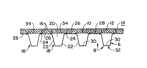
2 ¦ Referring to Figs. 1 and 2, a bridge 2 constructed in
3 accordance with the present invention is shown suspended between
4 spaced-apart bridge abutments 4. The bridge comprises a corru-
5i gated plate 6 having a multiplicity of parallel, side-by-side
6 ! corrugations 8 which extend in a longitudinal direction of the
71 bridge, that is which run from one ~ridge abutment 4 to the
81 other. The bridge further includes a flat plate 10 and a layer
9¦ of concrete 12 disposed on top of the flat plate and defining a
10¦ traffic carrying surface 14 of the bridge. Shear studs 16 are
11¦ secured, e.g. welded to the flat plate and they anchor the con-
l?l crete layer to the flat plate to thereby form a mechanically
13l interlock between them.
14¦ In the embodiment of the bridge illustrated in Fig. 2,
15¦ the corrugated plate is defined by a multiplicity of channel
1~¦ members 18 each of which defines an upwardly opening, generally
17¦ V-shaped channel 2~, that is a channel having inclined sides 22.
18 ¦A first, relatively narrow horizontally disposed flange 24 pro-
19 Ijects laterally from the upper end of one of the inclined channel
20 ¦sides while a second, relatively wide, horizontally disposed
21 ¦ flange 26 projects laterally from the upper end of the other
22 Iinclined channel side. Both flanges extend over the full length
23 ¦of the associated channel members. The wide flange of each
24 ¦channel member 18 is secured, e.g. spot, skip or continuously
25 ¦welded, or it is bolted to the narrow first flange 24 of the next
26 ¦ adjoining channel member.
27 Thus, in the illustrated embodiment, the corrugated
29 plate 6 is defined by the totality of channel members and the
3~1
32
ll ~290SlZ
wide flanges 26 define corrugation peaks 28 of the plate while
2 flat root sections 30 of the V-shaped channels 20 define corru-
3 gation troughs 32.
4 In the embodiment of the invention illustrated in Fig.
~l 2, wid~ flanges 26 further define the flat plate 10 which is
61 structurally continuous over the full width of the corrugated
7 plate. For this purpose, the wide flanges include lateral,
8 outboard extensions 34 which are stepped up so as to accommodate
9 the narrow flanges of the next adjoining channel members and
which have sufficient widths so as to overlap the wide flanges 26
11 of the adjoining channel members. In this manner, the outboard
12 extension 34 of one channel member covers and closes the upwardly
13 open V-shaped channel 20 of the adjacent channel member so that
14¦ when concrete is poured onto the resulting flat plate the fresh
15¦ concrete cannot enter the channel and the finished bridge ex-
16 ¦ hibits a plurality of side-by-side, hollow tubular members which
17 ¦ extend over its full length.
18 The outermost edge of the outboard extension 34 is
1~¦ suitably secured, preferably welded to the wide flange 26 of the
next adjoining channel member 18.
21 The embodiment of the invention illustrated in Fig. 2
22 is particularly adapted for short span bridges o-f relatively
23 lesser length. Thus, for a bridge having a length of 20 feet,
24 for example, the pitch of the corrugated plate, that is the
spacing between adjacent corrugation peaks 28 or corrugation
26 ¦ troughs 32 is 30 inches while the corrugation height, that is the
27 distance between the corrugation peaks and corrugation troughs is
228 12 inches. The corrugated plate has a wall thickness of 3/16th
31
32
l ~90~
inch and a root section 30 width of 4 inches. The concrete layer
21 height is between 3-1/2 to 4 inches while the shear studs 16 are
3 made of 1/2-inch diameter rod, the rod material and the plate
4 material having a minimum yield strength of 50,000 psi. Such a
5 ! bridge complies with AASHTO-HS 20-44 loading requirement.
6~ Referring now to Figs. 1 and 3 in another embodiment of
71 the invention, the bridge 2 is constructed in the above described
8¦ manner utilizing a plurality of side-by-side, parallel channel
9¦ members 18 which define corrugated plate 6 and flat plate 10 of
10¦ the bridge. Placed on top the flat plate 10 is a layer of con-
11l crete 12 which defines traffic bearing surface 14. A multi-
~ plicity of shear studs 16 welded to the flat plate 10 anchor the
13 I concrete layer to the flat plate and thereby form a mechanical
14 ¦ interlock between the two.
15 ¦ In addition, however, and to increase the overall
16 ¦ strength of the bridge, a second, lower corrugated plate 36 is
17 ¦provided. In the illustrated embodiment, the lower corrugated
18 ¦plate is defined by side-by-side corrugated plate sections 38,
19 ¦ each of which defines two full corrugations, that is two corru-
gation peaks 40 (which are relatively narrow) and two corrugation
21 ¦ troughs 42 (which are relatively wide). One lateral edge of each
22 ¦ corrugated plate section, say a righthand edge portion 44 is
23 ¦ stepped down to nest with a mating, relatively narrow, longi-
24 ¦ tudinal side flange 46 of the adjoining corrugated plate section.
25 ¦The overlapping plate portions are suitably secured to each
26 ¦ other, preferably with intermittently placed bolts 48, although
27 ¦other means for fastening the plates together such as welds,
28 ¦ rivets and the like may, be substituted.
29
31
321
I l~9~ Z
i The structure illustrated in Fig~ 3 is functionally
2 ¦ similar to that illustrated in Fig. 2. Again, it defines mul-
3 tiple, longitudinally extending tubular conduits which can be
4 utilized as above described and which render the bridge rela-
5 ¦ tively lightweight while giving it great strength and rigidity.
6 ¦ The concrete layer is fully supported over its full width so that
7 ¦ its thickness can be kept t~ a minimum. Of course, the addition
8 of the lower corrugated plate 36 almost doubles the strength and
9 rigidity of the bridge illustrated in Figs. 3 over that illu-
10 ¦ strated in Fig. 2.
111 The embodiment of the invention illustrated in Fig. 3
121 may, for example, be employed to conform a bridge having a span
13 ¦ of 30 feet with AASHTO-HS 20-44 loading requirements by providing
14 ¦ a 36-inch corrugation pitch, a corrugation height of 8 inches and
15 ¦ a concrete layer thickness of 6-1/4 inch. Again the corrugated
16 ¦ plate as well as the shear studs (dimensioned as discussed above)
17 I are constructed of steel having a yield strength of 50,000 psi.
18 In the example the upper corrugated plate has a (trough) root
19 ¦ section width of 2 inches and the lower corrugated plate has a
20 ¦ root section width of approximately 26 inches.
21 I Referring now to Fig. 4, in another embodiment of the
22 ¦ invention, the corrugated plate 6, flat plate 10-and concrete
23 ¦ layer 12 are constructed as above described. The bridge also
24 ¦ includes a lower corrugated plate 50 which is defined by the same
25 I channel members 18 which define the upper corrugated plate 6.
26 ¦ The only difference between the upper and lower corrugated plates
27 ¦ is that the channel members are inverted. Thus, the bridge
228 ~ illustrated in Fig. 4 also includes a lower flat plate 52 defined
31
32
l ~;~90~1~
1 by wide flanges 26 together with corresponding outboard exten-
2 sions 34. The upper and lower corrugated plates are suitably
3 secured to each other with welds, bolts, rivets or the like.
4 A bridge constructed as illustrated in Fig. 4 has a
5l somewhat greater strength and rigidity than the bridge illus-
61 trated in Fig. 3, primarily because the bridge includes a con-
7 tinuous lower flat plate 52. In all other respects the bridge is
8 constructed and functions as described above.
9 It will be observed that in the embodiments of the
invention shown in Figs. 3 and 4, the upper and lower corrugated
11 plates are nested one within the other, that is the corrugation
12 peaks and corrugation troughs of the upper and lower corrugated
13l plates contact and are secured to each other. As a result, the
14¦ overall height of the portion of the bridge defined by the corru-
15 ¦gated plates is substantially equal to the height of one corru-
16 ¦gated plate plus one corrugated plate thickness. This construc-
17 ¦ tion is particularly useful in connection with bridges having
18 ¦relatively high payloads yet relatively short spans where shear
19 ¦ forces are relatively high as compared to the bending momement.
20 ¦For bridges of greater spans, bending moments and the rigidity of
21 the bridge become of increasing significance and require a cor-
22 responding strengthening of the bridge.
23 Referring now to Figs. 5 and 7, a bridge 54 is again
24 suspended between abutments 4, but it comprises a plurality of
251 corrugated plate layers which are stacked one on top of the other
26¦ by contacting and securing to each other corrugation troughs of
27 ¦ the upper corrugated plate with corrugation peaks of the Lower
28 ¦corrugated plate in the manner more fully described below.
31
32
l~O~
1¦ Referring now specifically to Fig. 5, an upper corru-
2¦ gated plate 56 is constructed as above described from a plurality
31 of side-by-side channel members 18 which define upwardl~ open,
4l V-shaped channels 20 that are closed by wide, longitudinally
51 extending flanges 26 fitted with outboard extensions 34 so as to
6 Iclose the upwardly open channels. Overlapping portions of the
7 ¦outboard extensions and of the wide flange of adjoining channel
8 ¦members are again secured, e.g. welded together to define flat
9 ¦plate 10 which is structurally continuous over the width of the
1~ ¦corrugated plate. Placed on top of the flat plate 10 is the
11 ¦above described concrete layer 12 which defines traffic carrying
l?l surface 14 of the bridge. Studs 16 are used to mechanically
13 ¦interlock the concrete layer to the flat plate.
14¦ A lower corrugated plate 58 may be constructed of
15 ¦mutliple corrugated plate sections 60 which define parallel,
16 ¦ side-by-side, longitudinally running corrugations having alter-
17 ¦ nating, relatively narrow corrugation peaks 62 (of a width sub-
18 ¦ stantially equal to the corrugation troughs of the upper corru-
19 ¦ gated plate 56) and relatively wide corrugation troughs 64. One
20 ¦ of the lateral edge portions 66 is stepped down so as to nest
21 ¦ with short side flanges 68 of the adjoining corrugated plate
22 ¦ section so that the overlapping portions can be secured to each
23 ¦ other, for example, with bolts 70.
24 The embodiment of the invention illustrated in Fig. 5
is adapted for greater spans, say for a span of 45 feet. For
26 AASHTO-HS 20-44 loading requirements, the corrugated plates has a
27 23-inch pitch, a corrugation height of 8 inches and a plat,e
29 thickness of 3/16th with a yield strength of 50,000 psi. The
31
32
I 1~90512
1 concrete layer thickness is 6~3/4 inch while the upper plate has
2 a ttrough) root section width of about 2 inches and the lower
3 plate has a root section width of about 13 inches. By increasing
4 the corrugation height to 12" and the plate thickness to 1/4" the
bridge can have a span up to about 65 feet.
61 Referring to Figs. 5 and 7, the lower corrugated plate
7 I 58 may extend over the full length of the upper corrugated plate
8 56 as is shown for the first lower corrugated plate in Fig. 7.
9 The lower corrugated plates, however, may span a distance less
than the full length of the upper corrugated plate as is the case
11 with lower corrugated plates 72, 74 and 76 shown in Fig. 7. In
? such an event, ends 78 of the lower corrugated plates terminate
13l short of abutments 4 and the plates are centered with respect to
14¦ the longitudinal extent of the bridge so that they strengthen the
15 ¦bridge where it ls subjected to greatest stress.
16 I To prevent the accumulation of moisture and debris
17 ¦ within and to prevent animals from gaining access to the hollow
18 ¦interior of the lower corrugated plate through their open ends
19 178, Z-shaped end plates 79 or L-shaped end plates 81 may be
20 ¦suitably placed over the open ends as is illustrated in Fig. 7
21 ¦ and secured to the adjoining corrugation.
22 ¦ Figs. 7 and 10 also illustrate the manner in wich
23 ¦bridge 2 is supported by abutments 4. Each abutment includes a
24 ¦protruding ledge 120 on which is formed a pedestal 122. Ends 124
25 Iof the uppermost corrugated plate 56 and, as illustrated in Figs.
26 7 and 10 of the next lower corrugated plate 58, overlap the
27 pedestals and rest thereon. An elastomeric bearing pad 126 is
29~ interposed between the corrugated plates and the pedestal.
301
31
32
~ ~90~2
l Preferably, each corrugated plate end 124 is defined by ¦
2 a generally L-shaped end plate 128 which is suitably secured,
3 e.g. welded to the corrugated plates 56, 58 and which includes a
4 lower, horizontal leg 130 which rests on the elastomeric bering
51 pad. Anchor bolts 132 protrude from the abutment led~e 120 and
6 ¦ extend through suitably placed holes in the horizontal leg of the
7 ¦ end plate. Nuts attach the end plate and, therewith, the cor-
8 ~ rugated plates and the entire bridge to the anchor bolts and the
9 ¦ abutment. To permit thermal expansions of the bridge the anchor
10 ¦bolt holes in the horizontal leg 130 of one of the end plates 128
11 ¦ are elongated in the direction of the length of the bridge.
l? Referring now to Fig. 6, in yet another embodiment of
13 the invention, a bridge 80 is constructed of at least one upper
14 carrugated plate 82 and one lower corrugated plate 84, each of
which is constructed of corrugated plate sections 86 which define
l& alternating corrugation peaks and corrugation troughs 88, 90
17 which are laterally offset by one-half corrugation pitch so that
18 corrugation troughs of the upper plate are aligned with corru-
l9 gation peaks of the lower plate. Placed directly on top of the
upwardly facing surface of the upper corrugated plate is a con-
21 crete layer 92 which defines traffic carrying surface 14 of the
22 bridge.
23 To anchor the concrete layer to the corrugated plate,
24 the latter is constructed of so-called checkered plate, arranged
for example in a diamond pattern so that raised protrusions 94
26 which are uniformly distributed over the corrugated plate and
27 depressions defined by them face upwardly. The need for concrete
2B a choring st~ds (sho~n in Figs. 2-5) is there~y eliminated. The
32
~1 22
.
l.~9~)Sl~ I
I protrusiOns, which typically extend upwardly from a remainder of
2 the plate by up to l/8th inch or more, form a uniform, i.e.
3 evenly distributed mechanical interlock between the concrete
4 layer and the corrugated plate and thus, integrate the latter
5¦ with the former into a load bearing structure.
61 Since concrete has little tensional strength and since
71 the corrugations of the upper and lower plates have little trans-
I verse strength, a flat plate 96 defined by a plurality of inter-
9¦ connected flat plate sections 98 is used so as to render the flat
10¦ plate structurally continuous over the width of the corrugated
11¦ plate. The flat plate is interposed between the upper and lower
?~ corrugated plates 82, 84 to prevent the corrugations of the
13 plates from being opened, that is from being spread apart in a
14¦ lateral bridge direction when the bridge is subjected to its
5¦ design load. Thus, flat plate 96 performs the same function as
,61 the flat plates illustrated in Figs. 2-5 but, in the embodiment
17 ¦ ill~strated in Figs. 6, it is spaced apart from the concrete
18 ¦ layer by the upper corrugated plate. The flat plate itself is
19 ¦suitably secured to the corrugation troughs and peaks of the
20 ¦ upper and lower corrugated plates, respectively, as by welding or
21 ¦bolting it thereto.
22 ¦ For a sectional or modular construction of the bridge,
23 ¦ that is for a construction in which each corrugated plate section
24 ¦ has a width less than the overall width of the bridge, each
25 ¦section is fitted with a longitudinally extending, relatively
26 ¦ short side flange 100 along one edge of the section and a longi-
27 ¦ tudinally extending, relatively wide side flange 102 on the
29 jopposite side of the section so that portions of the relatively
31
32
l ~.~9()53LZ
1~ wide flanges of the upper and lower sections overlap and can be
21 secured, e.g. bolted to each other.
3l In the embodiment of the invention illustrated in Fig.
4 6, the upper corrugated plate is preferably constructed of
5' checkered steel plate while the lower corruga~ed plate is con-
6 ¦ structed of regular steel plate, both of which have a yield
7 ¦ stress of 50,000 psi. For the AASHTO-HS 20-44 loading require-
81 ments the plates have a thickness of 3/16th inch a corrugation
9 ¦ pitch of between 16 to 18 inches, and a corrugation depth of
10 ¦ between 6 and 8 inches. The flat plate 96 also has a 3/16th inch
11 ¦ thickness while the concrete protrudes 2 to 3 inches above the
~ ¦ corrugation peaks of the upper corrugated plate. Such a struc
13 ¦ ture is suitable for span lengths of between 20 to 40 feet. Of
14 course, by adding additional lower corrugated plates the span
length of the bridge can be increased as may be required.
16 I Referring now briefly to Figs. 8 and 9, a longitu-
17 ¦ dinally extending guard rail 104 may be installed along lateral
18 ¦ edges 106 of the bridge by arranging over the length of the
19 ¦ bridge a plurality of generally L-shaped channel members 108
20 ¦ (which may have the same profile as the corrugations of corru-
21 I gated plate 6). Each channel member includes a horizontal por-
22 ¦ tion 110 secured to the underside of corrugations 8 of the corru-
23 I gated plate with bolts 112, for example~ A vertical portion 114
24 ¦ of the channel member protrudes above road bed 14 and the guard
25 I rail is secured, e.g. bolted to its upper end. A gusset plate
26 I 116 is preferably bolted to the corrugated plate in alignment
27 ¦ with the channel member and welded to the latter. It includes a
28 I protruding section 118 which is secured, e.g. welded to the
29 channel member to rigidify its vertical portion.
32