Language selection

Search

Patent 1290651 Summary

Third-party information liability

Some of the information on this Web page has been provided by external sources. The Government of Canada is not responsible for the accuracy, reliability or currency of the information supplied by external sources. Users wishing to rely upon this information should consult directly with the source of the information. Content provided by external sources is not subject to official languages, privacy and accessibility requirements.

Claims and Abstract availability

Any discrepancies in the text and image of the Claims and Abstract are due to differing posting times. Text of the Claims and Abstract are posted:

  • At the time the application is open to public inspection;
  • At the time of issue of the patent (grant).
(12) Patent: (11) CA 1290651
(21) Application Number: 558089
(54) English Title: MULTIPLE HYDRAULIC CONTROL
(54) French Title: COMMANDE HYDRAULIQUE MULTIVOIE
Status: Deemed expired
Bibliographic Data
Abstracts

English Abstract


MULTIPLE HYDRAULIC CONTROL
ABSTRACT OF THE INVENTION
A kit is used for converting a single outlet
hydraulic system to a multiple outlet system. The kit
includes plural two-way, two-position solenoid operated
valves, gauged with their inlets connected in parallel
and their outlets serving as the multiple outlets. The
valves are operated by a control handle mounted on the
control lever of the single outlet system. Each valve is
controlled by an independent switch on the hand grip of
the handle. The control handle can thus be used both to
select an outlet and to control the flow through the
outlet.


Claims

Note: Claims are shown in the official language in which they were submitted.

- 8 -
CLAIMS:
1. A kit for converting to a plural outlet system
a single outlet hydraulic system having a single hydrau-
lic system outlet including two hydraulic system outlet
ports, means for supplying hydraulic fluid under pressure
to the hydraulic system outlet and means including a
manually operable lever for varying the hydraulic fluid
supply to the hydraulic system outlet, said kit compris-
ing
a plurality of two-way, two-position valves,
each having a valve inlet comprising two valve inlet
ports, a valve outlet comprising two valve outlet ports,
valving means operatively connected between the inlet and
outlet and having valve open and valve closed conditions,
respectively opening and closing communication between
the outlet and the inlet, and actuator means operatively
associated with the valving means for selectively actuat-
ing the valving means into the valve open and valve
closed conditions each actuator means being independent
of each other actuator means;
valve inlet coupling means coupling the valve
inlets in parallel for fluid communication therebetween;
means for connecting the coupled valve inlets
to the hydraulic system outlet;

- 9 -
a control handle including a hand grip and a
plurality of manually operable control means spaced
therealong for engagement by respective fingers of an
operator's hand;
means for mounting the control handle on the
manually operable lever of the hydraulic system; and
control circuit means connecting each valve
actuator means to a respective manually operable control
means for selective operation of the actuator means in
response to operation of the control.
2. A kit according to Claim 1 wherein the valves
are secured together in a unit.
3. A kit according to Claim 2 wherein each valve
inlet comprises at least one pair of inlet ports for
supply and return flow.
4. A kit according to Claim 3 wherein each valve
inlet comprises a second pair of inlet ports and wherein
the valves are stacked with adjacent valves having
aligned pairs of inlet ports.
5. A kit according to Claim 4 wherein each valve
is a spool valve, the valving means being a valve spool.
6. A kit according to Claim 5 wherein the valve
actuator means comprise solenoid actuators.
7. A kit according to Claim 6 wherein at least one


- 10 -

of the valves further comprises a spring return means
operatively associated with the valving means, to bias
the valving means towards the valve closed condition, and
the solenoid actuator is operatively associated with the
valving means to actuate the valving means to the valve
open condition.
8. A kit according to Claim 1 including quick
release coupling means for coupling the inlets to the
single outlet system.


Description

Note: Descriptions are shown in the official language in which they were submitted.


~L~29~6~i~


MULTIPLE HYDRAULIC CONTROL
FIELD OF THE INVENTION
The present invention relates to hydraulic
power systems and more particularly to the conversion of
a single outlet hydraulic power system to a multiple
outlet system.
BACKGROUND
In tractors and other equipment with hydraulic
power systems for operating auxiliary units, it is fre-
quently desirable to provide more outlets for the hy-
draulic system than those with which the original
equipment was supplied. Conventionally, this involves
plumbing in one or more additional hydraulic circuits,
including extra hydraulic lines and control valves at the
operator's station, e.g. in the cab of a tr~ctor. The
conversion is time consuming and costly and the potential
leak points are multiplied.
SUMMARY
The present invention is concerned with the
provision OI an alternative system for multiplying single
hydraulic outlets to provide plural outlets.
According to the present invention there is
provided a kit for converting to a plural outlet system a
single outlet hydraulic system having a single hydraulic


.. .

~06~;~


system outlet including two hydraulic system outlet
ports, means for supplying hydraulic fluid under pressure
to the hydraulic system outlet and means including a
manually operable lever for varying the hydraulic fluid
supply to the hydraulic system outlet, said kit compris-
ing:
a plurality of two-way, two-position valves,
each having a valve inlet comprisin~ two valve inlet
ports, a valve outlet comprising two valve outlet ports,
valving means operatively connected between the inlet and
outlet and having valve open and valve closed conditions,
respectively opening and closing communication between
the outlet and the inlet, and actuator means operatively
associated with the valving means for selectively actuat-
ing the valving means into the valve open and valve
closed conditions each actuator means being independent
of each other actuator means;
valve inlet coupling means coupling the valve
inlets in parallel for fluid communication therebetween;
means for connecting the coupled valve inlets
to the hydraulic system outlet;
a control handle including a hand grip and a
plurality of manually operable control means spaced
therealong for engagement by respective fingers of an


,~
~, .

5~L


operator's hand;
means for mounting the control handle on the
manually operable lever of the hydraulic system; and
control circuit means connecting each valve
actuator means to a respective manually operable control
means for selective operation of the actuator means in
response to operation of the control.
Coupling the valve inlets to a single system
outlet provides multiple outlets that are selectively
actuable. The control for the system outlet then con-
trols whichever outlets are selected by the operator
using the control handle.
Mounting the control handle on the control
lever at the operator's station allows an operator to
select the outlet to be powered then simultaneously to
control the flow to that outlet,
The valves may be stacked valves, coupled in a
unit, with the inlets in direct communication with one
another. With such an arrangement, the multiple outlet
system can be treated as a unit that connects to the
single outlet system with quick release couplings so that
it can be transferred from one piece of equipment to
another as required.


~9~51


BRIEF DESCRIPTION OF THE DRAWINGS
In the accompanying drawings, which illustrate
exemplary embodiments of the present invention..
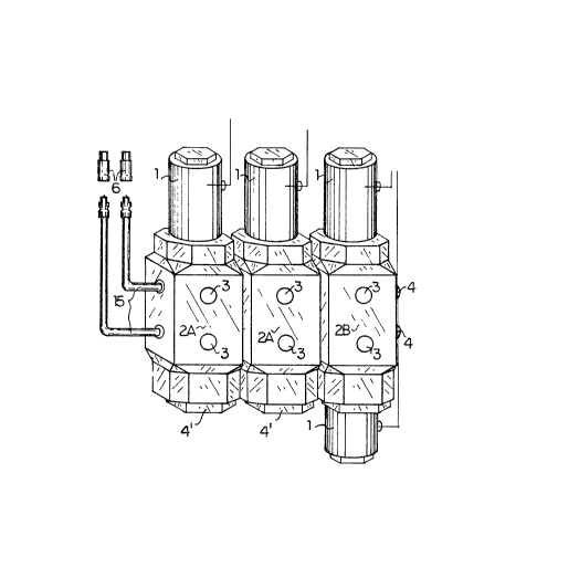
Figure 1 is an isometric representation of a
set of stacked valves;
~ igure 2 is a side elevation of a control
handle sectioned to show the internal structure; and
Figure 3 is a cross-sectional elevation of a
valve.
DETAILED DESCRIPTION
Referring to the accompanying drawings, Figure
1 illustrates a valve assembly consisting of three hy-
draulic selector valves 2A, 2A and 2B. Each valve is a
two-way, two-position valve constructed generally as
illustrated in Figure 4. The valve has a valve body with
an inlet including a pair of inlet ports 5, and an outlet
including a pair of outlet ports 3. The inlet passes
through the body so that when the valves are stacked as
illustrated in Figure 1, adjacent pairs of inlet ports on
adjacent valves are in alignment, so that hydraulic fluid
can pass into and from all three valves. The extra inlet
ports of the valve 2B are closed with plugs 4 IFigure 1~.
Each valve contains a spool 17 that can be displaced
along the valve body selectively to open or close commun-
ication between the inlet and the outlet.


,.~ .....

- ~9~51


In the valves 2A, the spool 17 is biased to a
valve closed condition, in which the communication be-
tween the inlet and the outlet is cut off, by a coil
spring 16 acting on the bottom of the spool and held in
place by a plug 4' threaded into the bottom of the valve
body. To move the spool to a valve open condition, in
which communication is established between the inlet and
outlet, a solenoid 1 is actuated, forcing the spool along
the valve body against the force of spring 16. The valve
2B is similarly constructed, but in this case the coil
spring 16 is omitted and a second solenoid 1 is mounted
on the valve body so that the spool 17 may be positively
displaced from either the open or the closed condition to
the other, with neither condition being a "default"
condition.
The inlet ports of the valve 2A on the left
hand side of the sides viewed in Figure l are connected
to respective hydraulic lines 5 which are in turn con-
nected to quic~ release hydraulic couplers 6 that mount
in the outlet ports of the single outlet hydraulic
system. The two outlet ports are thus coupled to the
inlet ports of all three valves and each valve can be
actuated to open and close communication between its
outlet and that of the slngle system. The two way valves


i5~


provide for supply and return flow, which may be rever-
sible depending on the control of the single outlet
system.
Figure 2 of the accompanying drawings illus-
trates a control module 11 with a series of on-off
switches 12. The switches are all connected to a power
supply 15 and each switch is connected to a respective
valve actuator solenoid 1 by an electric circuits 8. The
illustrated control module has a series of four switches
that can be used for a system with up to four solenoid
actuators 1 for the three valves 2A, 2A and 2B. The
control module is constructed as a control handle 11 with
the four switches 12 spaced along the handle. the
switches are normally open and close when pressed. The
control handle is equipped with a mounting bracket 13,
14 for mounting the handle on an existing hydraulic con-
trol lever (not illustrated~ of the original equipment
single outlet system. This means that the operator can
control both the selection of outlets and the flow to
~hose outlets with a single hand.
The use of quick release couplings connecting
the valves lnto the existing hydraulic system allows the

system to be transported readily from one hydraulic powPr
unit to another simply by uncoupling the hose connections


,~ ..... .

~:9~6Si


and the wiring harness.
While one embodiment of the present invention
has been described in the foregoing, it is to be under-
stood that other embodiments are possible within the
scope of the present invention. The invention is to be
considered limited solely by the scope of the appended
claims.


.. .

Representative Drawing
A single figure which represents the drawing illustrating the invention.
Administrative Status

For a clearer understanding of the status of the application/patent presented on this page, the site Disclaimer , as well as the definitions for Patent , Administrative Status , Maintenance Fee  and Payment History  should be consulted.

Administrative Status

Title Date
Forecasted Issue Date 1991-10-15
(22) Filed 1988-02-03
(45) Issued 1991-10-15
Deemed Expired 2008-10-15
Correction of Expired 2012-12-05

Abandonment History

There is no abandonment history.

Payment History

Fee Type Anniversary Year Due Date Amount Paid Paid Date
Application Fee $0.00 1988-02-03
Maintenance Fee - Patent - Old Act 2 1993-10-15 $50.00 1993-10-14
Maintenance Fee - Patent - Old Act 3 1994-10-17 $50.00 1994-10-14
Maintenance Fee - Patent - Old Act 4 1995-10-16 $250.00 1995-11-21
Maintenance Fee - Patent - Old Act 5 1996-10-15 $75.00 1996-10-15
Maintenance Fee - Patent - Old Act 6 1997-10-15 $75.00 1997-10-03
Maintenance Fee - Patent - Old Act 7 1998-10-15 $75.00 1998-10-14
Maintenance Fee - Patent - Old Act 8 1999-10-15 $75.00 1999-10-06
Maintenance Fee - Patent - Old Act 9 2000-10-16 $75.00 2000-10-04
Maintenance Fee - Patent - Old Act 10 2001-10-15 $100.00 2001-08-27
Maintenance Fee - Patent - Old Act 11 2002-10-15 $100.00 2002-09-27
Maintenance Fee - Patent - Old Act 12 2003-10-15 $100.00 2003-10-03
Maintenance Fee - Patent - Old Act 13 2004-10-15 $125.00 2004-10-07
Maintenance Fee - Patent - Old Act 14 2005-10-17 $125.00 2005-09-26
Maintenance Fee - Patent - Old Act 15 2006-10-16 $225.00 2006-09-26
Owners on Record

Note: Records showing the ownership history in alphabetical order.

Current Owners on Record
LASHTA, STEVE
Past Owners on Record
None
Past Owners that do not appear in the "Owners on Record" listing will appear in other documentation within the application.
Documents

To view selected files, please enter reCAPTCHA code :


To view images, click a link in the Document Description column. To download the documents, select one or more checkboxes in the first column and then click the "Download Selected in PDF format (Zip Archive)" or the "Download Selected as Single PDF" button.

List of published and non-published patent-specific documents on the CPD .

If you have any difficulty accessing content, you can call the Client Service Centre at 1-866-997-1936 or send them an e-mail at CIPO Client Service Centre.


Document
Description 
Date
(yyyy-mm-dd) 
Number of pages   Size of Image (KB) 
Representative Drawing 2001-07-19 1 19
Description 1993-10-23 7 196
Drawings 1993-10-23 1 33
Claims 1993-10-23 3 74
Abstract 1993-10-23 1 17
Cover Page 1993-10-23 1 11
Correspondence 2007-08-14 2 41
Correspondence 2008-01-08 4 193
Fees 1996-10-15 1 47
PCT 1995-11-21 2 50
Fees 1994-10-14 1 33
Fees 1993-10-14 1 20