Language selection

Search

Patent 1290730 Summary

Third-party information liability

Some of the information on this Web page has been provided by external sources. The Government of Canada is not responsible for the accuracy, reliability or currency of the information supplied by external sources. Users wishing to rely upon this information should consult directly with the source of the information. Content provided by external sources is not subject to official languages, privacy and accessibility requirements.

Claims and Abstract availability

Any discrepancies in the text and image of the Claims and Abstract are due to differing posting times. Text of the Claims and Abstract are posted:

  • At the time the application is open to public inspection;
  • At the time of issue of the patent (grant).
(12) Patent: (11) CA 1290730
(21) Application Number: 1290730
(54) English Title: DISCHARGE DEVICE FOR HOPPERS
(54) French Title: MECANISME DE VIDAGE DE TREMIES
Status: Expired and beyond the Period of Reversal
Bibliographic Data
(51) International Patent Classification (IPC):
  • B65G 65/44 (2006.01)
  • B65D 88/64 (2006.01)
  • B65D 90/58 (2006.01)
(72) Inventors :
  • SANDWALL, NILS (Sweden)
(73) Owners :
  • CONSILIUM MATERIALS HANDLING MARINE AB
(71) Applicants :
  • CONSILIUM MATERIALS HANDLING MARINE AB (Sweden)
(74) Agent: SMART & BIGGAR LP
(74) Associate agent:
(45) Issued: 1991-10-15
(22) Filed Date: 1987-03-11
Availability of licence: N/A
Dedicated to the Public: N/A
(25) Language of filing: English

Patent Cooperation Treaty (PCT): No

(30) Application Priority Data:
Application No. Country/Territory Date
8601161-6 (Sweden) 1986-03-12

Abstracts

English Abstract


TITLE: DISCHARGE DEVICE FOR HOPPERS
ABSTRACT OF THE DISCLOSURE
The invention relates to a device for a hopper
for crushed material. The hopper has a downwardly
narrowing portion which leeds to an outlet with
arcuate lateral edges, at which outlet a discharge
chute is pivotable between a folded-down position for
material discharge and a position for preventing
discharge. The chute is provided at its opposite
lateral edges with a pair of wedge-shaped deflector
plates which, as the chute is pivoted, sweep under
the arcuate lateral edges to push material away and
prevent it from being jammed between the chute and
the lateral edges of the hopper.


Claims

Note: Claims are shown in the official language in which they were submitted.

20615-865
THE EMBODIMENTS OF THE INVENTION IN WHICH AN EXCLUSIVE
PROPERTY OR PRIVILEGE IS CLAIMED ARE DEFINED AS FOLLOWS:
1. A hopper assembly for crushed material such as ore and
limestone, comprising:
a downwardly narrowing hopper having an outlet located at its
lower end defined by facing lateral arcuate edge portions,
a discharge chute being mounted at said lower end of said
hopper in a manner which permits said discharge chute to pivot
along an arcuate path concentric with said facing arcuate lateral
edge portions of said hopper, said discharge chute pivotable
between an open material discharging position and a closed
position which prevents material from being discharged from said
hopper,
said discharge chute including at one end an arcuate portion
conforming to said lateral arcuate edge portions of said hopper
outlet and at another end a straight portion which guides the
material discharged from said hopper,
said discharge chute including at each lateral edge thereof a
deflector plate extending upwardly from said discharge chute and
positioned at the junction between said straight and arcuate
portions, said deflector plates including an upper arcuate edge
portion which lies in the same vertical plane as said facing
lateral arcuate edge portions of said hopper outlet and adjacent
thereto, said plates serving to prevent material discharged from
said hopper from jamming between said facing lateral arcuate edge
portions of said hopper outlets and said discharge chute as well
as to assist in the removal of material from said outlet of said

20615-865
hopper during movement of said discharge chute to a closed
position.
2. The assembly of claim 1 wherein said deflector plates
are wedge-shaped.
3. The assembly of claim 1 wherein said hopper further
includes at its lower end a plate transverse to said lateral edges
fixed to an outer surface of and spaced from said hopper, said
fixed plate having a lower edge which is adjacent said straight
portion of said discharge chute when said discharge chute is in
the closed position.
4. The assembly of claim 1 wherein said discharge chute is
supported by a pivot arm attached to said hopper, said pivot arm
pivoting about an axis coinciding with the center of arc of said
lateral arcuate edge portions of said hopper.

Description

Note: Descriptions are shown in the official language in which they were submitted.


~ 29~7~0
20615-~65
The present invention relates to a device in a hopper
for crushed material such as ore and limestone, comprising a
downwardly narrowing hopper wi-th an outlet located at its lower
end with facing circular arcuate edges and a discharge chute,
which is mounted to pivot along a circular arcuate path concentric
with the circular arcuate lateral edges between a folded-down
position for discharging material from the hopper and a folded-up
position to prevent material discharge, said discharge chute
having arcuate edge portions conforming to the arcuate edges of
the hopper and straight edge portions connected thereto.
When such a chute is swung from the open to the closed
position the straight portion of the edge of the chute follows a
circular arcuate path from a downwardly inclined position to a
horizontal position, the straight edge forming the tangent to the
arcuate edge of the hopper. A wedge-shaped gap is thereby formed
between the edge of the hopper and the straight edge of the chute.
Junks of material can jam in this gap and prevent the chute from
moving all the way up.
The purpose of the present invention is to achieve a
device which prevents junks of material from jamming in the gap
between the hopper edge and the edge of the chute when the chute
is swung up to close the hopper outlet.
The invention provides a hopper assembly for crushed
material such as ore and limestone, comprising: a downwardly
narrowing hopper having an outlet located at its lower end defined
by facing lateral arcuate edge portions, a discharge chute being
mounted at said lower end of said hopper in a manner which permits
B
,,

~gO73S3
2g615-~5
said discharge chute to pivot along an arcuate path concentric
with said facing arcuate lateral edge portions of said hopper,
said discharge chute pivotable between an open material
discharging position and a closed position which prevents material
from being discharged from said hopper, said di.scharge chute
including at one end an arcuate portion conforming to said lateral
arcuate edge portions of said hopper outlet and at another end a
straight portion which guides the material discharged from said
hopper, said discharge chute including at each lateral edge
thereof a deflector plate extending upwardly from said discharge
chute and positioned at the junction between said straight and
arcuate portions, said deflector plates including an upper arcuate
edge portion which lies in the same vertical plane as said facing
lateral arcuate edge portions of said hopper outlet and adjacent
thereto, said plates serving to prevent material discharged from
said hopper from jamming between said facing lateral arcuate edge
portions of said hopper outlets and said discharge chute as well
as to assist in the removal of material from said outlet of said
hopper during movement of said discharge chute to a closed
pofi~cion.
la
- B

~X~373~)
During the closing movement, the deflector
plate sweeps across the underside of the arcuate
hopper edge and any junks of material between it and
the edge of the chute are pushed away by the front
edge of the deflector plate, so that the chute can
be rnoved unimpeded to its closed position.
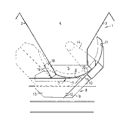
The invention will be described in more detail
with reference to an example shown in the accompanying
drawings, of which Fig 1 shows a longitudinal section
through a schematically shown hopper with a device
according to the invention, and Fig 2 shows a cross
section through one half of said hopper.
1 designates the lower portion of an upwardly
open hopper for crushed material such as ore and the
like. The hopper has a rectangular cross section with
inclined forward and rear walls 2 and 3 and side walls
4 to produce a downwardly narrowing shape. The side
walls 4 have lower vertical portions 5 with circular
arcuate edges 6, forming the lateral edges of the
hopper outlet 7.
A discharge chute generally designated 8, is
arranged below the outlet. The chute has a bottom 9
and inclined side walls 10 attached thereto, which
have an upper edge with an arcuate portion ll and
a straight portion 12. Vertical wall portions 13 are
joined~to the inclined side walls 10. The arcuate
portion 11 is concentric with the arcuate lateral
edges 6 of the hopper. The chute 8 is supported by
a pair of supporting arms 14 pivotally mounted in the
hopper, which arms are joined to hydraulic operating
cylinders (not shown). The pivot center of the
supporting arms 14 coincides with the center of the
arc of the lateral edges 6, so that the distance
between the arcuate lateral edges 6 of the hopper
~; 35 and the arcuate edge portions 11 of the chute are
kept constant as the chute is swung.
A

3(7
To prevent junks of material from being jammed
between the straight edge portions 12 of the chute and
the arcuate lateral edges 6 of the hopper when the
chute is swung up, a deflector plate 15 in the form of
a wedge is welded at one end of each vertical wall
portion 13 of the chute. The deflector 15 has an
arcuate upper edge 16 which lies close to the arcuate
lateral edge 6, as is clearly shown in Fig 1. When the
chute is swung from the position shown in Fig 1 with
solid lines to the position shown with dashed lines,
the front edge 17 of the deflector will push material
out of its way so that the chute can be swung unimpeded
to its closed position, i.eO with bottom line horizon-
tal. ~y virtue of the fact that the deflector 15 is
wedge-shaped and extends backwards all the way to the
arcuate edge portion 11 of the chute, there is no
possibility of material being jammed behind the
deflector and preventing the chute from being swung
down. Material which is pushed forward by the deflector
15 when the chute is swung up can if needed be pushed
into a gap 18 between the front wall 2 of the hopper 1
and a plate 19.
:
:
,~
~::
~,

Representative Drawing
A single figure which represents the drawing illustrating the invention.
Administrative Status

2024-08-01:As part of the Next Generation Patents (NGP) transition, the Canadian Patents Database (CPD) now contains a more detailed Event History, which replicates the Event Log of our new back-office solution.

Please note that "Inactive:" events refers to events no longer in use in our new back-office solution.

For a clearer understanding of the status of the application/patent presented on this page, the site Disclaimer , as well as the definitions for Patent , Event History , Maintenance Fee  and Payment History  should be consulted.

Event History

Description Date
Inactive: IPC from MCD 2006-03-11
Time Limit for Reversal Expired 2001-10-15
Letter Sent 2000-10-16
Grant by Issuance 1991-10-15

Abandonment History

There is no abandonment history.

Fee History

Fee Type Anniversary Year Due Date Paid Date
MF (category 1, 6th anniv.) - standard 1997-10-15 1997-09-23
MF (category 1, 7th anniv.) - standard 1998-10-15 1998-09-17
MF (category 1, 8th anniv.) - standard 1999-10-15 1999-09-15
Owners on Record

Note: Records showing the ownership history in alphabetical order.

Current Owners on Record
CONSILIUM MATERIALS HANDLING MARINE AB
Past Owners on Record
NILS SANDWALL
Past Owners that do not appear in the "Owners on Record" listing will appear in other documentation within the application.
Documents

To view selected files, please enter reCAPTCHA code :


To view images, click a link in the Document Description column. To download the documents, select one or more checkboxes in the first column and then click the "Download Selected in PDF format (Zip Archive)" or the "Download Selected as Single PDF" button.

List of published and non-published patent-specific documents on the CPD .

If you have any difficulty accessing content, you can call the Client Service Centre at 1-866-997-1936 or send them an e-mail at CIPO Client Service Centre.


Document
Description 
Date
(yyyy-mm-dd) 
Number of pages   Size of Image (KB) 
Abstract 1993-10-23 1 18
Cover Page 1993-10-23 1 13
Drawings 1993-10-23 1 17
Claims 1993-10-23 2 58
Descriptions 1993-10-23 4 140
Representative drawing 2000-08-15 1 12
Maintenance Fee Notice 2000-11-14 1 178
Fees 1999-09-15 1 39
Fees 1996-08-27 1 53
Fees 1995-09-26 1 46
Fees 1994-09-20 1 48
Fees 1993-09-28 1 30