Sélection de la langue

Search

Sommaire du brevet 1290730 

Énoncé de désistement de responsabilité concernant l'information provenant de tiers

Une partie des informations de ce site Web a été fournie par des sources externes. Le gouvernement du Canada n'assume aucune responsabilité concernant la précision, l'actualité ou la fiabilité des informations fournies par les sources externes. Les utilisateurs qui désirent employer cette information devraient consulter directement la source des informations. Le contenu fourni par les sources externes n'est pas assujetti aux exigences sur les langues officielles, la protection des renseignements personnels et l'accessibilité.

Disponibilité de l'Abrégé et des Revendications

L'apparition de différences dans le texte et l'image des Revendications et de l'Abrégé dépend du moment auquel le document est publié. Les textes des Revendications et de l'Abrégé sont affichés :

  • lorsque la demande peut être examinée par le public;
  • lorsque le brevet est émis (délivrance).
(12) Brevet: (11) CA 1290730
(21) Numéro de la demande: 1290730
(54) Titre français: MECANISME DE VIDAGE DE TREMIES
(54) Titre anglais: DISCHARGE DEVICE FOR HOPPERS
Statut: Périmé et au-delà du délai pour l’annulation
Données bibliographiques
(51) Classification internationale des brevets (CIB):
  • B65G 65/44 (2006.01)
  • B65D 88/64 (2006.01)
  • B65D 90/58 (2006.01)
(72) Inventeurs :
  • SANDWALL, NILS (Suède)
(73) Titulaires :
  • CONSILIUM MATERIALS HANDLING MARINE AB
(71) Demandeurs :
  • CONSILIUM MATERIALS HANDLING MARINE AB (Suède)
(74) Agent: SMART & BIGGAR LP
(74) Co-agent:
(45) Délivré: 1991-10-15
(22) Date de dépôt: 1987-03-11
Licence disponible: S.O.
Cédé au domaine public: S.O.
(25) Langue des documents déposés: Anglais

Traité de coopération en matière de brevets (PCT): Non

(30) Données de priorité de la demande:
Numéro de la demande Pays / territoire Date
8601161-6 (Suède) 1986-03-12

Abrégés

Abrégé anglais


TITLE: DISCHARGE DEVICE FOR HOPPERS
ABSTRACT OF THE DISCLOSURE
The invention relates to a device for a hopper
for crushed material. The hopper has a downwardly
narrowing portion which leeds to an outlet with
arcuate lateral edges, at which outlet a discharge
chute is pivotable between a folded-down position for
material discharge and a position for preventing
discharge. The chute is provided at its opposite
lateral edges with a pair of wedge-shaped deflector
plates which, as the chute is pivoted, sweep under
the arcuate lateral edges to push material away and
prevent it from being jammed between the chute and
the lateral edges of the hopper.

Revendications

Note : Les revendications sont présentées dans la langue officielle dans laquelle elles ont été soumises.


20615-865
THE EMBODIMENTS OF THE INVENTION IN WHICH AN EXCLUSIVE
PROPERTY OR PRIVILEGE IS CLAIMED ARE DEFINED AS FOLLOWS:
1. A hopper assembly for crushed material such as ore and
limestone, comprising:
a downwardly narrowing hopper having an outlet located at its
lower end defined by facing lateral arcuate edge portions,
a discharge chute being mounted at said lower end of said
hopper in a manner which permits said discharge chute to pivot
along an arcuate path concentric with said facing arcuate lateral
edge portions of said hopper, said discharge chute pivotable
between an open material discharging position and a closed
position which prevents material from being discharged from said
hopper,
said discharge chute including at one end an arcuate portion
conforming to said lateral arcuate edge portions of said hopper
outlet and at another end a straight portion which guides the
material discharged from said hopper,
said discharge chute including at each lateral edge thereof a
deflector plate extending upwardly from said discharge chute and
positioned at the junction between said straight and arcuate
portions, said deflector plates including an upper arcuate edge
portion which lies in the same vertical plane as said facing
lateral arcuate edge portions of said hopper outlet and adjacent
thereto, said plates serving to prevent material discharged from
said hopper from jamming between said facing lateral arcuate edge
portions of said hopper outlets and said discharge chute as well
as to assist in the removal of material from said outlet of said

20615-865
hopper during movement of said discharge chute to a closed
position.
2. The assembly of claim 1 wherein said deflector plates
are wedge-shaped.
3. The assembly of claim 1 wherein said hopper further
includes at its lower end a plate transverse to said lateral edges
fixed to an outer surface of and spaced from said hopper, said
fixed plate having a lower edge which is adjacent said straight
portion of said discharge chute when said discharge chute is in
the closed position.
4. The assembly of claim 1 wherein said discharge chute is
supported by a pivot arm attached to said hopper, said pivot arm
pivoting about an axis coinciding with the center of arc of said
lateral arcuate edge portions of said hopper.

Description

Note : Les descriptions sont présentées dans la langue officielle dans laquelle elles ont été soumises.

~ 29~7~0
20615-~65
The present invention relates to a device in a hopper
for crushed material such as ore and limestone, comprising a
downwardly narrowing hopper wi-th an outlet located at its lower
end with facing circular arcuate edges and a discharge chute,
which is mounted to pivot along a circular arcuate path concentric
with the circular arcuate lateral edges between a folded-down
position for discharging material from the hopper and a folded-up
position to prevent material discharge, said discharge chute
having arcuate edge portions conforming to the arcuate edges of
the hopper and straight edge portions connected thereto.
When such a chute is swung from the open to the closed
position the straight portion of the edge of the chute follows a
circular arcuate path from a downwardly inclined position to a
horizontal position, the straight edge forming the tangent to the
arcuate edge of the hopper. A wedge-shaped gap is thereby formed
between the edge of the hopper and the straight edge of the chute.
Junks of material can jam in this gap and prevent the chute from
moving all the way up.
The purpose of the present invention is to achieve a
device which prevents junks of material from jamming in the gap
between the hopper edge and the edge of the chute when the chute
is swung up to close the hopper outlet.
The invention provides a hopper assembly for crushed
material such as ore and limestone, comprising: a downwardly
narrowing hopper having an outlet located at its lower end defined
by facing lateral arcuate edge portions, a discharge chute being
mounted at said lower end of said hopper in a manner which permits
B
,,

~gO73S3
2g615-~5
said discharge chute to pivot along an arcuate path concentric
with said facing arcuate lateral edge portions of said hopper,
said discharge chute pivotable between an open material
discharging position and a closed position which prevents material
from being discharged from said hopper, said di.scharge chute
including at one end an arcuate portion conforming to said lateral
arcuate edge portions of said hopper outlet and at another end a
straight portion which guides the material discharged from said
hopper, said discharge chute including at each lateral edge
thereof a deflector plate extending upwardly from said discharge
chute and positioned at the junction between said straight and
arcuate portions, said deflector plates including an upper arcuate
edge portion which lies in the same vertical plane as said facing
lateral arcuate edge portions of said hopper outlet and adjacent
thereto, said plates serving to prevent material discharged from
said hopper from jamming between said facing lateral arcuate edge
portions of said hopper outlets and said discharge chute as well
as to assist in the removal of material from said outlet of said
hopper during movement of said discharge chute to a closed
pofi~cion.
la
- B

~X~373~)
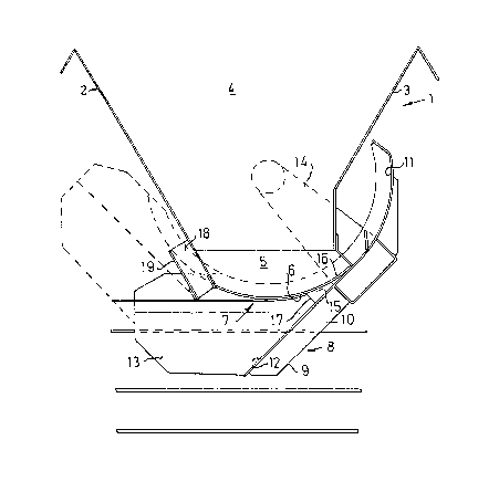
During the closing movement, the deflector
plate sweeps across the underside of the arcuate
hopper edge and any junks of material between it and
the edge of the chute are pushed away by the front
edge of the deflector plate, so that the chute can
be rnoved unimpeded to its closed position.
The invention will be described in more detail
with reference to an example shown in the accompanying
drawings, of which Fig 1 shows a longitudinal section
through a schematically shown hopper with a device
according to the invention, and Fig 2 shows a cross
section through one half of said hopper.
1 designates the lower portion of an upwardly
open hopper for crushed material such as ore and the
like. The hopper has a rectangular cross section with
inclined forward and rear walls 2 and 3 and side walls
4 to produce a downwardly narrowing shape. The side
walls 4 have lower vertical portions 5 with circular
arcuate edges 6, forming the lateral edges of the
hopper outlet 7.
A discharge chute generally designated 8, is
arranged below the outlet. The chute has a bottom 9
and inclined side walls 10 attached thereto, which
have an upper edge with an arcuate portion ll and
a straight portion 12. Vertical wall portions 13 are
joined~to the inclined side walls 10. The arcuate
portion 11 is concentric with the arcuate lateral
edges 6 of the hopper. The chute 8 is supported by
a pair of supporting arms 14 pivotally mounted in the
hopper, which arms are joined to hydraulic operating
cylinders (not shown). The pivot center of the
supporting arms 14 coincides with the center of the
arc of the lateral edges 6, so that the distance
between the arcuate lateral edges 6 of the hopper
~; 35 and the arcuate edge portions 11 of the chute are
kept constant as the chute is swung.
A

3(7
To prevent junks of material from being jammed
between the straight edge portions 12 of the chute and
the arcuate lateral edges 6 of the hopper when the
chute is swung up, a deflector plate 15 in the form of
a wedge is welded at one end of each vertical wall
portion 13 of the chute. The deflector 15 has an
arcuate upper edge 16 which lies close to the arcuate
lateral edge 6, as is clearly shown in Fig 1. When the
chute is swung from the position shown in Fig 1 with
solid lines to the position shown with dashed lines,
the front edge 17 of the deflector will push material
out of its way so that the chute can be swung unimpeded
to its closed position, i.eO with bottom line horizon-
tal. ~y virtue of the fact that the deflector 15 is
wedge-shaped and extends backwards all the way to the
arcuate edge portion 11 of the chute, there is no
possibility of material being jammed behind the
deflector and preventing the chute from being swung
down. Material which is pushed forward by the deflector
15 when the chute is swung up can if needed be pushed
into a gap 18 between the front wall 2 of the hopper 1
and a plate 19.
:
:
,~
~::
~,

Dessin représentatif
Une figure unique qui représente un dessin illustrant l'invention.
États administratifs

2024-08-01 : Dans le cadre de la transition vers les Brevets de nouvelle génération (BNG), la base de données sur les brevets canadiens (BDBC) contient désormais un Historique d'événement plus détaillé, qui reproduit le Journal des événements de notre nouvelle solution interne.

Veuillez noter que les événements débutant par « Inactive : » se réfèrent à des événements qui ne sont plus utilisés dans notre nouvelle solution interne.

Pour une meilleure compréhension de l'état de la demande ou brevet qui figure sur cette page, la rubrique Mise en garde , et les descriptions de Brevet , Historique d'événement , Taxes périodiques et Historique des paiements devraient être consultées.

Historique d'événement

Description Date
Inactive : CIB de MCD 2006-03-11
Le délai pour l'annulation est expiré 2001-10-15
Lettre envoyée 2000-10-16
Accordé par délivrance 1991-10-15

Historique d'abandonnement

Il n'y a pas d'historique d'abandonnement

Historique des taxes

Type de taxes Anniversaire Échéance Date payée
TM (catégorie 1, 6e anniv.) - générale 1997-10-15 1997-09-23
TM (catégorie 1, 7e anniv.) - générale 1998-10-15 1998-09-17
TM (catégorie 1, 8e anniv.) - générale 1999-10-15 1999-09-15
Titulaires au dossier

Les titulaires actuels et antérieures au dossier sont affichés en ordre alphabétique.

Titulaires actuels au dossier
CONSILIUM MATERIALS HANDLING MARINE AB
Titulaires antérieures au dossier
NILS SANDWALL
Les propriétaires antérieurs qui ne figurent pas dans la liste des « Propriétaires au dossier » apparaîtront dans d'autres documents au dossier.
Documents

Pour visionner les fichiers sélectionnés, entrer le code reCAPTCHA :


Pour visualiser une image, cliquer sur un lien dans la colonne description du document. Pour télécharger l'image (les images), cliquer l'une ou plusieurs cases à cocher dans la première colonne et ensuite cliquer sur le bouton "Télécharger sélection en format PDF (archive Zip)" ou le bouton "Télécharger sélection (en un fichier PDF fusionné)".

Liste des documents de brevet publiés et non publiés sur la BDBC .

Si vous avez des difficultés à accéder au contenu, veuillez communiquer avec le Centre de services à la clientèle au 1-866-997-1936, ou envoyer un courriel au Centre de service à la clientèle de l'OPIC.


Description du
Document 
Date
(aaaa-mm-jj) 
Nombre de pages   Taille de l'image (Ko) 
Abrégé 1993-10-23 1 18
Page couverture 1993-10-23 1 13
Dessins 1993-10-23 1 17
Revendications 1993-10-23 2 58
Description 1993-10-23 4 140
Dessin représentatif 2000-08-15 1 12
Avis concernant la taxe de maintien 2000-11-14 1 178
Taxes 1999-09-15 1 39
Taxes 1996-08-27 1 53
Taxes 1995-09-26 1 46
Taxes 1994-09-20 1 48
Taxes 1993-09-28 1 30