Note: Descriptions are shown in the official language in which they were submitted.
.'~l
~l 2~ i8
CHANNEL DEVICE AND TUBE CONNECTION AND THEIR FABRICATION PROCEDURES
The invention is concerned with a channel device, especially for
recordings of thermal conductivity, viscosity, density, dielectric
constants, refractive indices, etc. of materials such as fluids and
gases (called samples), where the material under investigation is
guided through a measuring channel with at least one sensor and at
least one inlet and one outlet orifice for the sample. The
invention also concerns the fabrication procedure of the channel
device, especially the recording unit for determining the thermal
conductivity, viscosity, density, dielectric constant, etc. of
samples where the material under investigation is passed through or
brought into a measuring channel which is equipped with sensors and
actuators.
The aim of the invention is to create a measuring arrangement
capable of on-line recordings whicll is extremely sensative even for
a very small sample volume and can be miniaturized for mass
production, using photolithographic, thin-film and solid-state
techniques.
~ ~90~.~8
28173-1
According to one aspect, the invention provides a device
for measuring at least one characteristic of a fluid, said
device comprising:
means defining a measuring channel of a predetermined shape
for conducting fluid flow therethrough; an inlet orifice and an
outlet orifice for conducting the fluid into and out of said
measuring channel; at least one sensor located adjacent said
measuring channel for measuring the one characteristic of the
fluid; said means defining said measuring channel including a
substrate and a wall having opposite ends sealingly adhered to
said substrate, said wall extending away from said substrate to
define said measuring channel of a predetermined shape. The
wall may be deposited by evaporation, spin-on, sputter, drop-on,
reactive deposition, CVD (chemical vapour deposition), PECVD
(plasma enhancer chemical vapour deposition), etc., techniques
and consist e.g. of synthetic material, glass, ceramic, Si3N4,
SiO2, SiO or combinations of these materials.
According to another aspect, the invention provides a
method for manufacturing a device for measuring at least one
characteristic of a fluid, said device having a wall defining
a measuring channel, an inlet orifice and an outlet orifice for
conducting fluid into and out of the measuring channel, and at
least one sensor for measuring at least one characteristic of
the fluid which flows through the measuring channel, said
method comprising the steps of: providing a substrate;
depositing on the substrate a first body of dissolvable
material having a shape corresponding to the shape of the
~ ;~9(~95~3
28173-1
measuring channel of the measuring device; controlling the
shape of the first body of dissolvable material to obtain
a measuring channel having appropriate dimensions for measur-
ing said one characteristic of the fluid; forming the wall by
depositing onto the first body of dissolvable material a second
body of material by one of evaporation, spin on, drop on,
sputtering, reactive deposition; dissolving the first body of
dissolvable material by contacting the dissolvable material
with a solvent which dissolves the first body of dissolvable
material but does not interact with the material of the sub-
strate and the wall; and attaching the at least one sensor to
one of the substrate and the wall by one of evaporation, spin
on, drop on, sputtering, reactive deposition, chemical vapor
deposition, plasma enhanced chemical vapor deposition, and ion
implantation.
According to another aspect, the invention provides a tube
connection for a device for measuring at least one characteris-
tic of a fluid, said tube connection comprising: a substrate;
a tube connected to said substrate; and a wall formed by a
wall-forming layer deposited onto the substrate and over at
least portions of the tube by a technique selected from a group
consisting of drop on, evaporation, sputtering, spin on,
reactive deposition, CVD, and PECVD whereby said wall adheres
tightly to at least parts of the tube and at least part of the
substrate in such a way that it keeps the end of the tube open
and forms a cavity together with the substrate which represents
an extension of the tube.
~ ~9(3~ 8
28173-l
The fabrication procedure for such a connection is
characterized, according to the invention, in that a dis-
solvable substance, i.e. photoresist, synthetic resin, etc., is
deposited onto a substrate as well as into a tube which can be
mounted (i.e. glued) onto the substrate in such a way that this
dissolvable substance forms a continuation of the tube. A
layer is then deposited onto the dissolvable substance so that
it covers this substance as well as at least a part of the tube
and at least a part of the substrate and forms a tight and
sealing connection with the tube as well as with the substrate.
The deposition of the layer may be performed by evaporation,
drop-on, sputtering, spin-on, reactive deposition, CVD, PECVD,
etc. The dissolvable substance can be dissolved and removed
through the open end(s) of the tube and/or through the open end
of the continuation which was formed by the dissolvable sub-
stance, using a solvent or procedure which will not affect the
substrate or the layer or the tube.
The evaluation and analysis of the measurements is per-
formed by electronic devices which are connected to sensors and
actuators which are arranged in and/or on the layer and/or inand/or on the substrate. The temperature raise of the heating
layers, the creation of surface accoustic waves and all other
actuations which are necessary for proper recordings, can be
generated by appropriate electronic devices.
It is easy to see that recording arrangements, which are
differing from the ones described above, can be produced, using
the invented fabrication techniques, i.e. miniaturized
~ ;~90~8
28173-1
chromatographs, pH-meters, press~lre sensors, etc.
The selection of the dissolvable substances and their
solvents can, to a large extent, be left to specialists.
-4a-
9U~8
28173-1
Aspects of the present invention are illustrated, merely
by way of example, in the accompanying drawings, in which:
Figures 1, la and lc depict a cross-sectional view of
the channel device of the present invention;
Figure lb is a graph showing the temperature of the
sample flowing through the channel device over time;
Figures 2 and 2b depict a cross-sectional view of a
channel device for measuring viscosity and dielectric constants;
Figure 2a is a graph depicting the slope of capacitance
change and velocity of a sample in the calculation of viscosity;
Figure 3 is a schematic of a device consisting of a
transmitter and receiver for measuring sample density;
Figure 3a is a cross-sectional view showing the location
of the transmitter and receiver relative to the substrate;
Figure 4 is a view showing the connection of tubes to
the substrate and channel layer by an adhesive layer;
Figure 5 is a cross-sectional view showing inlet and
outlet tube positions relative to the sensor positions;
Figure 6 is a side view depicting the indentation of the
tubes in the substrate;
Figure 7 schematically depicts the connection of the
tube to the substrate via an adhesive layer; and
Figures 8 and 9 are top views of a multiple
tube/multiple channel device.
Figure 1 shows a channel device which is especially
designed for recording thermal conductivity and viscosity of a
fluid or a gas. A layer(2) is deposited on a substrate(l) in such
~ ~9~`35~ 28173-1
a way that a measuring channel is formed which has at least one
inlet orifice(4) and one outlet orifice(5). The layer(2) is
deposited onto the substrate(l) in such a way that a dissolvable
substance is first deposited which has the shape of the measuring
channel(3) on top of which the layer(2) is deposited, covering the
dissolvable substance and at least parts of the substrate(l), so
called boundary parts (2'), on which the layer(2) adheres
tightly. Then, the dissolvable substance will be dissolved
through the inlet and/or outlet orifices(4,5). Thus, the
measuring channel(3) is formed by the substrate(l) and the
layer(2). Actuators and/or sensors can be arranged on and/or in
the substrate(l) and/or on and/or in the layer(2) in order to
equip the measuring channel(3) with the desirable recording,
sensing, and/or actuating units. The various sensor and/or
actuator layers on and/or in the substrate(l) as well cover
layers(8) on the substrate(l) are to be deposited before the
deposition of the dissolvable substance. It is, however, possible
to subsequently passivate the inside of the measuring channel(3)
by inserting cover layers(8'') (Figure lc) or to increase the
measuring channel(3) by etching or to modify the characteristics
of the actuators and/or sensors by appropriate surface treatments.
3.~8
Heating layers(6,6') are shown as an example in Fig 1. in an
indentation in the substrate(l) and on the layer(2), which can be
formed by evaporation, implantation, doping, etc. The electrical
connections to these actuators are not shown. Temperature
sensors(7,7') are arranged in the substrate(l) and on the layer(2).
The temperature sensors(7,7') can consist of serniconductor layers,
doped layers, metal layers, etc. Fig lc shows the layers 6' and 7'
as being contained in layer(2); they can also be covered by a cover
layer(8''). That is possible in particular if the layer(2) or the
substrate(l) consists of silicon which can be formed into a sensor
or actuator by doping or reactive deposition. In this case the
layer(2) or the substrate(l) is part and/or basis for the sensor of
actuator units.
The layers(6 and 7) can be, as shown in Fig 1., deposited in
indentations in the substrate(l) or on the substrate(l)(Fiy la).
The layers(6 and 7) can also be covered by a cover layer(8) in
order to prevent modifications of the layers (6 and 7). Another
layer (9) can be put on top of layer (2) and the layers (6' and7')
which can also be thicker to mechanically stabili~e the channel
device.
The deposition of the layers(2,8,9,8'etc) can be performed by
drop on, or spread on, sputtering, evaporation, spin on, etc
procedures.
~I X9()~358
The thickness of the layer(2) is advantageously between 1 um and
50 um, the height of the measuriny channel(3) up to 50 um, the
width of the measuring channel(3) can be between 1 um and 500 um
and the length might be up to several 10 mm. These values can be
changed, however, depending on the various applications. In most
cases it might be advantageous to have the height of measuring
channel(3) much smaller than the width in order to provide an
optimum contact between the sample and the sensors and actuators.
The thickness of the sensor and actuator layers is usually in the
range of 0.2 um and 40 um.
The viscosity measurement (Fig lb.) is performed by applying a
heat pulse through the heating layer(6,6') onto the sample gas or
liquid, which flows through the measuring channel, and measuring
the resulting temperature change of the sample with the temperature
sensors 7 and/or 7'. The time between ~he heat pulse application
and the temperature change, measured with the sensors 7 or 7'
determines the velocity of the sample in the solution which, in
turn, is inverse proportion to the viscosity. The pressure
difference between the inlet(4) and outlet(5) of the measuring
channel(3) has to be known or controlled and can be measured with
pressure sensors(7''). Pressure sensors can be avoided in case of
using a reference measuring channel(3) and the same pressure
difference in both channels.
~ ~t()'3~8
Thermal conductivity can be measured by applying a certain
amount of heat with a certain amplitude course and detecting the
occurrance of the temperature maximums, the amplitude course and
the decrease of the maY~imum at the temperature sensors(7)(Fig lc).
All the explanations for Fig 1. are in principle valid also for
the following figures and the described characteristics can be
com'oined with the following ones:
Fig 2. shows a channel device for recording viscosity and/or
dielectric constants. This channel device is in principle designed
similar to the one described in Fig 1.: conducting layers(10,10')
are deposited on the substrate(l) and the layer(2), forming a
capacitor. As soon as the sample moves into and through the
measuring channel(3), which was previously filled with air or was
evacuated, the capacitance of the layers(10,10') will be changed,
as shown in Fig 2a. The slope of the capacitance change is
proportional to the velocity of the sample in the measuring
channel(3) and permits the calculation of the viscosity.
It is advantageous, and increases the accuracy of the device, if
the height of the measuring channel(3) has the same value as the
thickness of the cover layer(8') in Fig 2.
The dielectric constant can be determined from the capacitance
of the device as soon as the measuring channel(3) is completely
filled with the sample.
'3(3~t.S~3
Fig 2b. shows a possible design of the channel device where the
substrate(1) consists of a basic material (ie. silicon or p-doped
Si)(1') topped by an n-doped layer (1''), forming a barrier layer.
Viscosity and dielectric constant measurements can be performed as
described above.
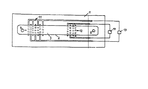
Density measurements of the sample can be performed by the
device shown in Fig 3. and Fig 3a. Transmitter(11) and receiver
layers(12) are arranged on indentations or on the surface of a
piezoelectric substrate. The transmitter layers(11) are connected
to high frequency generators~13), supplying 20 to 50kHz in the low
voltage range and generating surface accoustic waves in the
substrate(1). The resonance signal, detected by the receiver
layer(12), can be changed or damped in dependance of the density of
the sample in the measuring channel(3).
Fig 4. shows two tubes(17) connected to the substrate(1), ie. by
an adhesive layer(15). The two tubes(17) are connected to a
layer(2) which forms a channeltl8) with the substrate(1), adheriny
tightly to the tubes(17) and the substrate(1) as well. The
transition between the layer(2) and the tubes(17), kinks, exposed
bends, etc. can be strengthened mechanically by supportin~
layers(16) consisting of the same material or a material different
from that of layer(2). The fabrication of such a connection is
per ormed by depositing a dissolvable substance onto the ends of
the tubes(17) and onto the substrate(1) with the desired shape of
~ ~9()~8
the channel(18). The shape of the dissolvable substance can be
obtained, for instance, by photolithographic processes. The
layer(2) will be deposited onto the dissolvable substance in such a
way that the layer(2) forms a tight connection with the tubes(17)
and the substrate(1). The dissolvable substance will be dissolved
through the tubes(17). This technique allows the design of
connections between and to tubes of various, especially very small,
dimensions.
Fig 5. shows a design, appropriate to forming inlet and outlet
orifices(4,5) of measuring channels(3). The tubes(17) replace the
orifices(4,5) in the substrate(1). The design of the measuring
arrangement with sensors and actuators can be as described in Figs
1 to 3. The layer(2) can be covered by a protective layer(16')
which can be deposited in the same way as layer(2) consisting of
the same, or a different material (ie. glue), as layer(2). The
endings of the tubes(17) can be tilted.
Fig 6. shows that the tubes(17), especially their endings, can
be covered by the layer(2) and thereby tightly connected to the
substrate(1). The layer(16) can be of additional support and
increase the adhesion of the tubes(17) to the substrate(1). Fig 6.
also shows the tubes(17) can be placed in indentations(19) in the
substrate(1). The cross section of the tubes(17) can be of any
shape, ie. round, rectangular, etc.
~ X~ 5~3
The same techniques which permit the producti.on of tube
connections also permit the fabrication of special tube
continuations (Fig 7.): a tube(17) which can be connected by an
adhesive layer to a substrate(l) wi.ll be covered at its one ending
by a dissolvable substance which also covers the substrate(l),
being especially shaped at this part, ie. like a nozzle. The
layer(2) will be deposited onto at least part of the tube(l7), at
least parts of the dissolvable substance and at least parts of the
substrate(l). The dissolvable substance will be dissolved, leaving
a nozzle-like continuation of the tube(l7), formed by the layers(2)
and the substrate(l), and which can be used ie. for injection of
substances into the body tissue, etc. A similar nozzle-like
extension of the tube(17) is also shown in Fiy 4., created by the
layer(2'), which can be mechanically protected and/or strengthened
by an additional layer(16).
Fig 8. shows several tubes(17) which are not necessarily
arranged in parallel, and which are connected by a channel(3) which
is f ormed by the layer(2) and the substrate(l). The endings of the
tubes(17) on the lefthand side of Fig 8. are combined by the
measuring channel(3) of decreasing cross sections. The measuring
channel(3) finally splits up into several channels which can have
dif f erent cross sections, each of which can be connected to a
tube(17). The described invention allows the fabrication of almost
any kind of bifurcation, cross section and channel shape in order
to establish connections of, and among, numerous tubes creating the
~I X~0~ 3
possibility of forming valve-like control elements, flow
regulators, etc.
It is also possible to etch the measuring channel~3) as shown in
Fig 8. into the substrate(l) in order to achieve a smooth
transition between the tubes(l7) and the measuring channel(3).
Preferable diameters of the tubes(17) for the described fabrication
procedures are in the range between 5 um and 500 um. It is also
possible to connect two tubes(17) with each other which are placed
next to each other or located in such a way that their ends are
almost touching each other.
The invented channel devices and the tube connections can be
used for investigations of body and tissue liquids, for delivery of
substances to various ie. nerves, organs, etc. and for industrial
applications, ie. ink jet recorders, fuel injection systems, or
other devices where pipe systems, consisting of fine tubes, have to
be connected to each other or external, macroscopic, supply
systems. A big advantage of the invention is also that the
described channel devices yield precise results also in case of
extremely small sample volumes, representing unique measuring units
regarding response time, accuracy, resolution and reproductibility.
~ 29~ i8
The materials forming the layer(2) or (16) can consist of
organic substances, such as synthetic resin, polymers, epoxy resin,
ect. or any other organic susbstances such as Si3N4, SiO2, SiO,
SiC, ect. or substances with similar mechanical and or electrical
qualities.
The connections to the sensors and actuators can be established
by thin film interconnect paths, deposited in similar ways as
described above.
It is, of course, possible that one measuring channel(3)
contains several sensors and/or actuators and combinations thereof
which can be arranged on and/or in the substrate(l) and/or on
and/or in the layer(2).
Light sources and light detectors can be used for refraction
index measuremen.s: light can be, for instance, transferred
through a light permeable layer(2) and light detectors will measure
reflected and or transmitted light intensities which can be used,
for instance, in order to calculate the refraction index of the
sample. The light can also be transmitted through the tubes(17) or
the tubes(17) can be replaced by optical fibers.
~ ll these values, of course, can be used in order to determine
and analyze the composition of the sample.
3U9~3
Fig. 9 shows a device for flow regulations; the flow of a
sample, ie. from tube(17') to tube(17'') in the channel, formed by
layer(2), can be changed or totally directed into the tube
(17''''). Miniaturized valve and flow control units can be
fabricated.
Fig. 3a shows, in dashed lines, the connections of the
substrate~l) to a supporting substrate(l''') which ie. could be an
IC socket, consisting of a gold plated surface, which can be, in a
well known way, sealed to a Si substrate(l). Tubes can be soldered
to the substrate(l''') forming inlet(4') and outlet(5') orifices
for the measuring channel(3). The sensors can be connected via
wires(21) through ceramic feed throughs(20).
A temperature sensor(22) and a heating layer(23) is shown in
Fig.2b. allowing evaporation heat measurements. For that reason, a
channel is filled with the sample, the temperature of which will be
measured. The evaporating sample attracts evaporation heat from
the environment, which can be measured by the sensor(22). The
temperature slope is shown in Fig. 2a by the dashed line. The
evaporation heat can be calculated from the time course of the
temperature between To (temperature in the beginning of the
measurement, where the measuring channel is filled with the sample)
and Tl(end temperature, where the measuring channel is empty).
Capacitance measurements can be performed at the same time,
determining the amount of the substance in the channel, ect..
14
90~8
It is obvious that sensors and actuators, as shown in Fig 2.,
can be arranged next and/or above each other.
-15-