Note: Descriptions are shown in the official language in which they were submitted.
~g~oz~
The present invention is directed to an automatic
packaging machine having individual controlled atmosphere
chambers for each package movable along a conveyor and more
specifically to controlled atmosphere chamber means
comprised of a plurality of package receiving base members
movable along a first closed path conveyor and a plurality
of covers connected to a common atmosphere controlling
means movable along a second closed path partially
overlapping the first closed path for sealing engagement
lo with the base members.
It is well know from industrial practice,
technical magazines and international patent literature
that various packaging machines are provided with means for
controlling the atmosphere completely or partially during
the package filling and sealing operation. In such
machines, the empty bags are transferred from a forming
station to a filling conveyor and subsequent to being
filled, the bags are transferred into a chamber which is
then sealed. The interior of the sealed chamber is then
subjecting to a vacuum or other controlled atmosphere
depending upon the nature of the packaging operation.
During the transfer of the bags from the forming
stations to the filling stations and from there to the
controlled atmosphere chambers, numerous disadvantages can
arise which would restrict the efficiency of the entire
packaging process. There is always the possibility of
mishandling the bag during the numerous transfers with the
possible consequent spilling of the content of the bag
before the bag can be sealed. The frequent transferring of
the bag also leads to the possibility of the bunching up of
the bags or a jamming of the bags on the various conveyors
utilized in the multiple transfer operation.
According to the present invention, there is
provided a packaging machine comprising first conveyor
means movable along a first path; a plurality of upwardly
open receptacles mounted on said first conveyor means for
~k
~9~
movement therewith along said first path; means for forming
and directly inserting a package vertically downwardly in~o
each of said upwardly open receptacles, second conveyor
means disp~sed above said first conveyor means ~or movement
along a second path at least partially coincident with said
first path; a plurality of cover means carried by said
second conveyor means for movement into sealing engagement
with a respective upwardly open receptacle having an open
package therein to define a sealed chamber; atmosphere
controlling means connected to each of said cover means for
controlling the atmosphere in each sealed chamber; and
means for removing each package from a respective
receptacle; wherein said means ~or forming and directly
inserting a package into each of said receptacles includes
package forming means comprised of a plurality of
vertically disposed mandrels movable about a circular path
at least partially coincident with said first closed path;
sheet feeding means for supplying package forming material
to each mandrel in sequence; and means associated with each
mandrel for inserting an open package downwardly into each
receptacle.
Thus, the present invention provides a new and
improved packaging machine which overcomes all of the
shortcomings of the prior art packaging machines by
introducing the bags immediately after their formation
directly into the base portion o~ the controlled atmosphere
chamber and leaving each bag in the same base member during
all subsequent operations before removal as a completely
filled sealed bag. As a result, possible jamming and
mishandling of the bags is prevented.
Embodiments of the invention will now be
described, by way of example, with reference to the
accompanying drawings, in which:
Figure 1 is a schematic perspective view of an
embodiment of packaging machine according to the present
~29~)2~
invention showing the specific components of each conveyor
in a first position;
Figure 2 is a schematic view of a packaying
machine similar to that shown in Figure 1 with the
components of the conveyor systems disposed in a second
position;
Figure 3 is a perspective view of a packaging
machine similar to that shown in Figure 2 with the
components of each conveyor system and disposed in a third
position;
Figures 4 - 8 show different configurations of the
first and second conveyor paths with the portions thereof
which are adapted to be disposed in coincident overlapping
relation shown in heavy solid lines;
Figures 9 - 13 show a plurality of additional
closed path configurations wherein the first and second
conveyor means are shown with the coincident overlapping
portions shown in heavy solid lines and wherein the path of
the bag forming means is shown adjacent the opposite end of
the first closed path;
Figure 14 is a schematic view similar to Figure
1 but utilizing a second modified bag forming means; and
Figures 15 - 18 are schematic views similar to
Figure 1 but utilizing a third, fourth, fifth and sixth
modified bag forminy means.
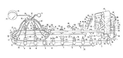
The packaging machine as shown in Figures 1 - 3,
inclusive, is comprised of a first endless conveyor 25 and
a second endless conveyor 26 disposed in two superimposed
parallel planes such that the second endless conveyor 26 is
disposed above the first endless conveyor 25 with a
substantial proportion of the second conveyor 26 being
aligned with the first conveyor 25. The plurality of
upwardly open receptacles 1 - 2~ are mounted on the first
endless conveyor 25 in equally spaced relation for movement
along a first closed path. A plurality of covers for the
open receptacles identified by I-X are mounted on the
~.'
..
~9~ 2~
second endles~ conveyor 26 in equally spaced relation with
the spacing between each cover being equal to the spacing
between each receptacle on the first endless conveyor 25.
A driving arrangement is provided for the conveyors 25 and
26 so as to synchronize the movement of the receptacles 1
- 24 with the covers I-X upon movement of the covers and
receptacles along their respective closed paths. Each
cover will be brought into sealing engagement with a
respective receptacle to define a sealed chamber therein.
A vacuum pump 29 is connected to a rotatable
plenum chamber 28 by means of a pipe 30 and the plenum
chamber 28 which is rotatable with the conveyor 26 is
connected to each cover I-X by means of a flexible conduit
28'. The vacuum pump 29 is provided with a suitable
pressure gauge 29' and each of the sealed
2~
chambers defined by the receptacles 1-24 and covers I-X are
provided with a pressure gauge 60.
Sealing jaws (not shown) are located inside each cover
member for heat sealin~ the packages after the chambers have been
pressurized to the desired value. The packages are heat sealed
by the sealing jaws which are connected by suitable wiring
through the flexible conduit 28' to the rotary pulse distributor
32 which in turn in connected by slip rings to a pulse generator
31.
The first conveyor 25 has a generally oblong configuration
with the pressure treatment apparatus for the filled bags being
located at one ourved end of the conveyor. A bag forming appara-
tus is located at the opposite curved end of the conveyor and is
comprised of a rotatable mandrel 42 having a plurality of arms
upon which the bag is formed. A supply of flexible film 43 is
located above the mandrel, whereby the package forming material
is fed vertically downwardly into close proximity with the radial
outer face of an arm o~ the mandrel. The lower end of the sheet
material is clamped against the mandrel by means of a clamp 46
and a sheet of material 124 for forrning a single package is
severed from the remaining sheet supply by means of a cutter 47.
The endless sheet supply may be already preprinted with labels
for the packages so that the individual sheets 124-129 will be
already laid out on the endless sheet supply. Each cut sheet is
held on the respective arm of the mandrel by a vacuum system (not
shown) so that as the mandrel 42 is rotated, the individual
sheets are formed into packages as indicated by the various
stages of bag formation 120-123. As shown in Figure 1, a com-
pletely formed bag 119 has been ejected from the mandrel into the
receptacle 1 on the conveyor 25 by means of a plunger mechanism
~Z 9~ V2~
45 controlled by the cam 44. The entire bag forming and ejection
apparatus is old and well known in the art and does not ~orm a
part o~ the present invention, but is used ln con~unction with
the upwardly open receptacles 1-24 inclusive which constitute
part of the presen-t invention~
As the conveyor moves the receptacles 1-24 along the closed
path, each bag will stop at a filiing station 3~, whereby the bag
is filled with the desired contents. The contents for the
present invention may be a loose granular material such as coffee
or the like. The filled bag will then move to a tamping station
34, where a tamper will press the filled material firmly into the
bag. As the filled bag is moving from the filling station 33 to
the tamping station 34, a projection extending from the bottom of
the receptacle will pass over a vibrating member in order to
vibrate the loose granular material in the package to settle it
evenly within the package or bag. The projection extending from
the bottom of each receptacle is connected to a movable bottom
wall in the receptacle.
The bag then moves to a measuring station 36 having conven-
tional means for measuring the level of the filled material
within the bag. The bag will then move to a station 37 having
suitable fin~ers for forming the bellows in the sides of the bay
to facilitate a subse~uent closing operation. The bag will then
move to the next station, wherein a cutter 38 will sever the
excess material o~ the bag.
After these preliminar~ operations, the bag which is still
in the open condition, will move to a station wherein the cover
on the second conveyor 26 will be mated with the upwardly open
receptacle on the conveyor 25, so as to enclose the filled bag in
a sealed chamber. Assuming it is desirable to evacuate the air
. ., ,.,.. , .:, .
~91~2~L '
from the bag prior to sealing the bag, the vacuum pump 29 will be
operated to evacuate the air rom the sealed chamber having the
filled bag th~rein. As the bag continues it~ movement on the
conveyor 25, the sealing jaws will heat seal the upper ends of
the bag. The chamber will subsequently be returned to atmospher-
ic pressure and the cover will be separated from the outwaxdly
open mandrel. As indicated by the arrow, the sealed upper end o~
tha bag 102 will then be folded over and upon reaching the
statlon 3~, a plunger will press the folded flap against the
upper sur~ace of the bag to achieve the ~inal flattening of the
bag. At the next station, a tape applying device 40 applies a
strip of adhesive tape to hold the Elap down against th~ upper
surface of the bag in sealed relation. At the subseguent sta-
tion, a transfer device 41 will grip the bag 99 and lif~ it onto
a third conveyor 27 for transfer to a suitable packaging station.
To ~acilitate the gripping of the bag 99 by the transfer device
41, the cam track will push the bottom of the upwardly open
receptacle upwardly to push the sealed bag ~urther out of the
receptacle. The empty receptacle will then continue around the
conveyor to receive another empty bag from the bag forming
mandrel.
Each of the bags shown in Figure 1 are numbered consecutive-
ly ~rom 95 to 119, wh'le the bags belng Eormed are numbered
consecutively ~rom 120 to 124. Additional sheets for ~orming the
bags are illustrated on a sheet supply by the numerals 125-129.
In Figure 2, which is a substantially identical view to Figure 1,
the bags have been moved through ten stations and in Figure 3 the
bags have been moved an additional seven stations. Thus, it is
clear that once a bag is formed on a bag forming mandrel, it is
trans$erred into a receptacle and remains in the same receptacle
7-
., , ... ,., :. ; .,;;.,,,, .i,, ,~,. . .
Z~
during the entire operation until the completely filled, formed
and degassed bag is removed from its r~ceptacle by the transfer
device 41.
While a vacuum pump has been illustrated in Figures 1-3, it
is possible that it may be necessary to subject the filled bag to
a pressurized inert gas 3 in which c~se a suitable pump could be
provided for connection to each of the sealed chambers for
carrying out such a pressurizing operation prior to the sealing
of the bags within the sealed chamber.
In the examples shown in Figures 1-3, the first and second
conveyors 25 and 26 both move along closed oblong paths, each
having the same curvature at one end so that portions of the two
paths may be superimposed on each other. Other forms of paths
are shown in Figures 4-8 with the portions which will be over-
lapped shown in heavy solid lines. Still further arrangements of
the two conveyors have been illustrated in Figures 9-13 with the
path of the bag forming apparatus being superimposed at the
opposite end of the elongated conveyor path oE the first convey-
or.
Figure 1~ shows an embodiment similar to Figure 1 insoar as
the arrangement oE the firsk and second conveyors 25 and 26 is
concerned, but wherei.n the bag forming apparatus is offset to one
sicle o the conveyor so that the arm o the mandrel having a
completed bag thereon, will come into alignment with an upwardly
open receptacle travelling along the Eirst closed path o the
first conveyor.
The embodiment of Figure 15 is substantially identical to
the embodiment of Figures 1-3 insofar as the first and second
conveyors 25 and 26 and the associated apparatus are concerned.
-8-
. . . . . ........ .......
~9~21
However, in Figure 15, the bags are formed by any suitable bag
forming appara-tus and convayed along a linear conveyor 49 with
the end oE the conveyor 49 being aligned with an upwardly open
receptacle. Suitable means are provided on the end of the
conveyor ~or transferring an upwardly open bag downwardly into an
upwardly open receptacle.
The embodiment of Figure 16 is similar to the embodimen~ of
P'igure 14 inasmuch as the bag forming is carried out by means of
a rotatable mandrel having a plurality of arms. However, the
mandrel 42' in Figure 16 is rotatable hy a horizontal axis and is
provided with a plurality of bag forming arms which are all
located in a common vertical plane disposed above the path of the
first conveyor 26. Thus, a completely filled bag will be present
on the vertically downwardly extending arm and transfer means are
provided within the arm for transferring the formed bag downward-
ly into the upwardly open receptacle aligned therewith.
In the embodiment of Figure 17, the first and second convey-
ors and the pressure treatment apparatus are substantially
identical to all the previous embodiments. However, in this
case, a conventional bag forming and filling apparatus 43 is
provided wherein the flaps on the upper end of the bag are
flattened into engagement with each other by means o~ a crimping
apparatus 48, but the bags are not sealed. The ~illed bag is
then deposited into an upwardly open conveyor, thereby eliminat-
ing the need ~or the Eilling and level measuring apparatus at
subsequent stations. The bags are still vibrated and excess
material of the flaps are trimmed oEf by cutter 38 prior to
subjecting the bag to a pressurized treatment.
~ he embodiment of Figure 18 is similar to the embodiment of
Figure 16, wherein the bag forming apparatus is comprised of a
--~3-- . .
129~2~. -
matldrel 42' rotatable about a vertically disposed axis and havinga plurality of radially extending arms all disposed in a common
horizontal plane. Thus, it is necessary for the first conveyor
25 to have a tilted portion for tilting the receptacles thereon
into a horizontal position for insertion of a completed bag from
one o the arms of the mandrel 42'' into the receptacle. The
receptacle having the bag therein is then tilted back to the
upright position for all of the subsequent operations previously
descri~ed.
While the lnvention has been particularly shown and de-
scribed with reference to preferred embodiments thereof, it will
be understood by those in the art that the foregoing and other
changes in form and details may be made therein without departing
from the spirit and scope of the invention. : :
--10--