Note: Descriptions are shown in the official language in which they were submitted.
-2- ~"3~
BACKGROUND AND SUMMARY OF THE INVENTION
Ad~ustable tube clamping connectors have been widely
used and there are many types of inner tube gripping devices
in the prior art. The present invention is designed to hold
the inner tube more firmly without causing any deformation or
damage to the inner tube.
BRIEF DESCRIPTION OF THE DRAWINGS
Fig. 1 is an exploded view of the conventional
adjustable tube clamping connector.
Fig. 2-1 is a longitudinal section of the
conventional adjustable tube clamping connector.
Fig. 2-2 iS a view of a clamping piece of the
conventional adjustable tube clamping connector.
Fig. 2-3 is a cross section of one conventional
adjustable tube clamping connector.
Fig. 3-1 is a longitudinal section of the
conventional adjustable tube clamping connector.
Fig. 3-2 iS a view of another clamping piece of the
conventional adjustable tube clamping connector.
Fig. 3-3 iS a cross section of another conventional
adjustable tube clamping connector.
Fig. 4 is an exploded view of the improved adjustable
tube clamping connector of this invention.
Fig. 4-1 is a longitudinal section of the said
improved tube clamping connector.
Fig. 4-2 is a cross section of the said improved
adjustable tube clamping connector.
-3~
As shown in Fig. 1, the conventional adjustable tube
elamping eonnector comprises an outer tube, an inner tube and
a elamp. The outer tube has a longitudinal open slot in one
side. The elamp is welded to the outer tube and has two lugs
on the open slot. The lugs have cavities and are slightly
open. When the lugs are brought together by a screw bolt and
nut, the outer tube with slot will be elamped to grip and hold
the inner tube firmly. To give added strength and pressure
for the outer tube to grip the inner tube, two elamping pieces
are fitted in the cavities of the lugs.
Also as shown in Fig. 2 the clamping piece is in
inverted U shape (as shown in Fig. 2-2) and fitted in the
eavity of the lug with its two ends keeping contact with the
external surface of the outer tube (as shown in Fig. 2-3).
When the lugs are brought by the screw bolt and nut, the
elamping pieces will make the sloted outer tube to grip and
hold the inner tube firmly so that it ean bear greater
vertieal load. But for laek of the effeet of reinforeing, the
lugs and the outer tube will be deformed and damaged when they
are tightened by the screw bolt. ~s a result, it will be
diffieult to adjust the eonnection next time.
The applieation of another elamping pieee is shown in
Figs. 3-1 and 3-3. The clamping piece in the shape of a block
~5 (as shown in Fig. 3-2) is fitted in the lug with its back
perfeetly eontaeting the bottom of the lug and its end well
contacting the external surface of the outer tube. So it can
give added strength and pressure to the clamp. But the
elamping effect depends on the thickness of the elamping piece
or the contaet area of the clamping piece with the outer tube.
The larger the contaet area the greater the clamping force.
Sinee sueh elamping pieees are made by punehing press, their
thickness is limited. Otherwise, it would be diffieult to
proeess and too mueh waste would be resulted from punehing.
It does not meet the economic prineiple of mass production.
~'
--4--
So the major disadvantage of the conventional device is the
limitation in thickness and the reduction of steadiness and
safety in clamping.
In view of the abo~e mentioned disadvantages, the
inventor worked hard to make improvements and developed this
invention. So the main object of this invention is to provide
an improved adjustable tube clamping connector which has
eliminated the disadvantages of the conventional connectors by
employing a pair of clamping pieces with extensions which give
added strength and pressure to ensure the steadiness and
safety in clamping.
Another object of this invention is to provide an
improved adjustable tube clamping connector of which the
clamping piece can be made by punching in mass production so
as to reduce the cost.
According to the invention there is provided an
improved adjustable tube clamping connector comprising: an
outer tube having an open slot at one side, an inner tube
fitte* in the outer tube for adjustable connection, a clamp
attached by welding to the outer tube and having on the slot
two lugs with cavities for a pair of clamping pieces to fit
in, and two clamping pieces each having a pair of extensions
with curved surfaces and fitted in the cavities of the lugs in
such way that the back of the clamping piece is closely
attached to the bottom of the cavity and the curved surface
keeps close contact with the surface of the outer tube so that
they can give added strength and pressure when the lugs are
brought together by the screw bolt and nut.
DETAILED DESCRIPTION OF TH~_~$~ M~ODIMENT
Below is a detailed description of the preferred
embodiment of this invention.
~'
-5- ~ 3 ~ ~r~
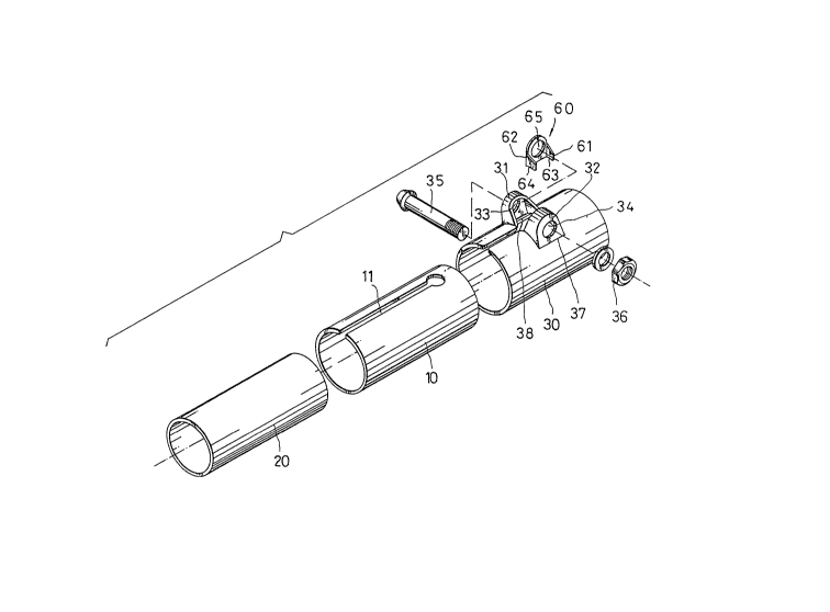
As shown in Fig. 4 the improved adjustable tube
clamping connector comprises an outer tube 10, an inner tube
20, a clamp 30, and a pair oE clampiny pleces. The outer tube
10 has an open slot 11 at one side. The clamp 30 is welded to
the outer tube 10 and has two lugs 31, 32 on the open slot.
The lugs 31, 32 have bolt holes 33, 34, for a screw bolt 35 to
fit in. The lugs 31, 32 can be brought together by the screw
bolt 35 and nut 36. Each of the clamping pieces 60 has two
extensions 61, 62 from the edges of the front side, and a hole
65 in the flat part for the bolt 35 to fit in after the clamp-
ing pieces are fitted in the cavities of the lugs 31, 32. The
clamping pieces 60 are fitted perfectly in the cavities of the
extensions 61, 62 and have curved surfaces 63, 64 as shown
in Fig. 4-1 which keep close contact with the wall surface of
the outer tube 10 as shown in Fig. 4 2 and give added strength
to the lugs 31, 32. With these larger curved surfaces 63, 64
of the extensions 61, 62, greater pressure can be applied on
a greater area of the outer tube when the screw bolt 35 is
tightened. The inner tube 20 is thus gripped and held firmly
and can bear greater working pressure.
~ Cont'd/6
.~