Note: Descriptions are shown in the official language in which they were submitted.
1291725
Descri~tion
Load Lifting Device Load Sensing
Technical Field
This invention relates to a load lifting
device having a load carrying member and sensors for
determining the presence of a load on the load
carrying member, and more particularly, to a lift
mast assembly for a material handling vehicle having
a plurality of load carrying members and first and
second sensors and reflectors on each of the first
and second load carrying members for sensing the
presence and position of a load on the load carr~ing
members.
Backaround Art
Load lifting devices having load carrying
members suitable for engaging and carrying a load
have been in use for many decades. Typically, the
load lifting device (masts, booms, and lifting
linkages) is mounted on a vehicle and supports the
load carrying members (forks and the like) for
elevational movement relative to the vehicle. Some
examples of vehicles of this type include lift
trucks, telescopic material handlers, and track and
wheel loaders. The load carrying members, which
includes material handling forks, are mounted on the
load lifting device and elevationally movable for
retrieving and depositing loads at various
elevational locations.
In order to lift a load, the load lifting
device must be positioned so that the load carrying
members are disposed beneath the load. The load
carrying members are then elevated until the load is
engaged by and fully supported thereon. During this
1~917~
--2--
loading process, there is a strong potential for the
load to become skewed, pitched, and tipped relative
to the load carrying members resulting in the load
not being squarely carried on the load carrying
member. The load not being accurately positioned on
the load carrying member would adversely effect
material handling and load transferring operations.
This is particularly important in automated
manufacturing and storage systems where driverless
automatic guided vehicles are used to transport
loads. Therefore, there is a need to sense when a
load is squarely and properly positioned on the load
carrying members so that the material handling
function may be carried out with a maximum amount of
efficiency and accuracy.
one attempt to solve a portion of this
problem i8 taught in Japanese Patent Publication No.
61-15040, 1986 to Kabushlki Kaisha Komatsu
Seisakusho, dated April 22. In this publication, a
mechanical touch switch is provided on a load
carrying member of a lift truck lift mast assembly
adjacent a juncture of connection between the
vertically and horizontally extending portions of the
load carrying member. This, however, is an
unsatisfactory solution for several reasons. Since
the switch is mechanical and requires physical
movement of a mechanical actuator to actuate the
switch, there is the potential for switch failure due
to excessive forces being applied to the switch and
the mechanical switch actuator by the load.
Also, the mechanical switch actuator is
frequently subjected to cyclical forces caused by
loading and unloading of the load. Thus, improper
switch adjustment due to wear, bending, movement and
1;~9172S
68297-911
the like occurs. This causes improper switch operation and
results in inaccurate, incorrect, and erroneous sensing of the
actual position of the load on the load carrying members. As a
re~sult, placement of the load during load transfer operations is
inaccurate and requires frequent adjustment of the switch and
switch actuator.
The switch of the above-noted Japanese Patent is
connected to the load carrying member adjacent the juncture of
connection of the first and second end portions of the load
carrying member so that the switch will be closed whenever an end
portion of the load nearest the juncture of connection of the load
carrying members horizontally and vertically oriented end portions
~first and second end portions) contacts the mechanical switch
actuator. This a~umes that when the end portion of the load
ad~acent the switch is ~roperly posltloned that the entire load is
properly positioned and squarely at rest on the second end portion
of each of the load carrying members. This is, of course, a false
assumption since the load may be skewed and/or tipped and/or
tilted relative to the second end portions of the load carrying
member while making contact with the mechanical switch actuator.
Therefore, no positive and accurate sensing arrangement has been
provided to sense when a load is squarely at rest on the load
carrying members second end portion and closely adjacent the first
end portion of the load carrying member.
Disclosure of the Invention
In one aspect the present invention provides a load
lifting device, comprising, a load carrying member having a first
~:91'72~i
68297-911
end portion and a second end portion extending outwardly from said
first end portion; a first sensing means for delivering a first
slgnal from a first sensing location adjacent said first end
portion and receiving a reflection of said first signal; a second
sensing means for delivering a second signal from a second sensing
location adjacent said first end portion and receiving a
reflection of said second signal, said second sensing location
being positioned at a lower elevation than said first sensing
location; a first reflecting means for receiving said first signal
at a first reflecting location adjacent the second end portion and
delivering a reflection of said first signal in a direction toward
said first sensing means; a second reflecting means for receiving
said second signal at a second reflecting location adjacent the
second end portlon and delivering a reflection of said second
signal in a direction toward said second sensing means, said first
and second reflecting location being spaced from one another, said
sensing and reflecting means being free from contact with a load
carried on the load carrying member and providing accurate sensing
of the position of the load on the load carrying member.
In another aspect the present invention provides a lift
mast assembly, comprising: a pair of spaced apart uprights; a
carriage mounted on and movable along said pair of spaced apart
uprights; a first load carrying member having a first end portion
and a second end portion extending outwardly from said first end
portion; a second load carrying member having a first end portion
and a second end portion extending outwardly from said second load
carrylng member first end portion, said first end portions of the
~91~25
~ 8297-911
first and second load carrying members being connected to the
ca;rriage at spaced apart locations; a first sensing means for
delivering a first signal from a first sensing location adjacent
the flrst end portion of the first load carrying member and
receiving a reflection of said first signal; a second sensing
means for delivering a second signal from a second sensing
location adjacent said first end portion of the first load
carrying member and receiving a reflection of-said second signal,
said second sensing location being at a lower elevation than said
first sensing location; a third sensing means for delivering a
third signal from a third sensing location adjacent said first end
portion of the second load carrying member and reflection of said
third signal; a fourth sensing means for delivering a fourth
signal from a fourth sensing location adjacent said first end
portlon of the second load carrying member and receiving a
reflection of said fourth signal, said fourth sensing lo.ation
being positioned at a lower elevation than said third sensing
location; a first reflecting means for receiving said first signal
at a first reflecting location adjacent the second end portion of
the first load carrying member and delivering a reflection of said
first signal in a direction toward said first sensing means; a
second reflecting means for receiving said second signal at a
second reflecting location adjacent the second end portion of the
first load carrying member and delivering a reflection of said
second signal in a direction toward said second sensing means,
said first and second reflecting locations being spaced from one
another; a thlrd reflecting means for receiving said third signal
1~91725
68297~
at a third reflecting location adjacent the second end portion of
the second load carrying member and delivering a reflection of
sa:id third signal in a direction toward said third sensing means;
and a fourth reflecting means for receiving said fourth signal at
a 1Eourth reflecting location adjacent the second end portion of
the second load carrying member and delivering a reflection of
said fourth signal in a direction ~oward said fourth sensing
means; said third and fourth reflecting locations being spaced
from one another, said sensing and reflecting means being free
from contact ~ith a load carried on the load carrying members and
providing accurate sensing of the position of the load on the load
carrying members.
In yet another aspect the present invention provides an
automatic guided vehicle, compri~lng~ a vehicle frame having a
longitudinal axis; a pair of spaced apart elevationally oriented
uprights connected to said vehicle frame and longitudinally
movable along said longitudinal axis bet~Jeen spaced apart
locations on said vehicle frame; a carriage mounted on and movable
along said palr of spaced apart uprights between elevationally
spaced apart positions; a first load carrying member having a
first end portion and a second end portion extending outwardly
from said first end portion; a second load carrying member having
a first end portion and a second end portion extending outwardly
from said second load carrying member flrst end portion, said
first end portions being elevationally oriented and connected to
the carriage at spaced apart locations; a first sensing means for
delivering a first signal from a first sensing location ad~acent
1~9172S
6~297-911
the first end portion of the first load carrying member and
receiving a reflection of said first xignal; a second sensing
means for delivering a second signal from a second sensing
location adjacent the first end portion of the first load carrying
member and receiving a reflection of said second signal, said
second sensing location being positioned at a lower elevation than
said first sensing location; a third sensing means for delivering
a third signal from a third sensing location adjacent the first
end portion of the second load carrying member and receiving a
reflection of said third signal; a fourth sensing means for
delivering a fo~rth signal from a fourth sensing location adjacent
the first end portion of the second load carrying member and
receiving a reflection of said fourth signal, said fourth sensing
location belng posltioned at a lower elevation than sald thlrd
sensing location; a first reflectlng means for receiving sald
first signal at a first reflecting location adjacent the second
end portion of the first load carrying member and delivering a
reflection of said first signal in a direction toward said first
sensing means; a second reflecting means for receiving said second
signal at a second reflecting location adjacent the second end
portion of the first load carrying member and delivering a
reflection of said second signal in a direction toward said second
sensing means, said first and second reflecting locations being
spaced from one another; a third reflecting means for receiving
said third signal at a third reflecting location adjacent the
second end portion of the second load carrying member and
delivering a reflection of said third signal in a direction toward
1~9~
6~297-911
said third sensing means; a fourth reflecting means for receiving
said fourth signal at a fourth reflecting location ad~acent the
second end portion of the second load carrying member and
delivering a reflection of said fourth signal in a direction
toward said fourth sensing means, said third and fouxth reflecting
locations being spaced from one another, said sensing and
reflecting means being free from contact with a load carried on
the load carrying members and providing accurate sensing of the
position of the load on the load carrying members.
Since the sensing and reflecting means are free from
contact with the load at all times during operation, the potential
for damage is substantially reduced. Therefore system operation
will be continuous and uninhibited. Because the sensing means
rely on signal interference rather than
7a
1;~9~
--8--
mechanical actuation, the potential for failure due
to wear is eliminated. Thus, the reliability of the
system is greatly improved.
The sensing and reflecting means are
positioned to not only determine when the load is
appropriately and closely positioned adjacent the
first end portion of the load carrying members but
also whether or not the load is accurately supported
on the second end portion of the load carrying
members. Therefore, the problems with the load being
cocked, skewed, tilted, or tipped are overcome since
the sensors require the load to be squarely placed on
the load carrying members. In situations where the
load is not squarely placed on the load carrying
members, not all the sensors will be actuated.
Therefore operation of the lift mast assembly and/or
vehicle will be conditioned to respond in a
preselected manner.
The signals delivered by the sensing means
must receive a positive reflection of the light
signal from the associated reflecting means in order
to send a signal to the control unit telling the
control unit that the load is properly placed on the
load carrying members. Because the signals require
this positive reflection, the potential for
inadvertent signals being delivered is reduced.
Brief Description of the Drawinas
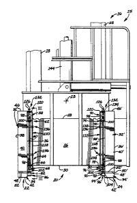
Fig. 1 is a diagrammatic side elevational
view of a material handling vehicle showing a lift
mast assembly mounted on the vehicle, a carriage
mounted on the lift mast assembly, a load carrying
member mounted on the lift mast assembly, sensing and
directing means mounted on the load carrying member
~91725
_g
and a load squarely carried on the load carrying
member;
Fig. 2 is an enlarged partial diagrammatic
front elevational view of the material handling
vehicle of Fig. 1 showing the load carrying members,
the carriage, a portion of the lift mast assembly,
and first, second, third, and fourth sensing and
reflecting means in greater detail;
Fig. 3 is an enlarged diagrammatic view
taken along lines III-III of Fig. 2 with portions
broken away showing the sensing and reflecting means
in greater detail; and
Fig. 4 is a diagrammatic schematic
representation of a control system suitable for
controlling operation of the lift mast assembly in
response to signals delivered from the sensing means.
Best Mode For Carryina Out the Invention
With reference to the drawings, a material
handling vehicle 10, which is preferably an automatic
guided vehicle of the driverless free ranging type,
has a frame 12, a longitudinal vehicle axis 13, and a
plurality of ground engaging wheels 14. At least one
of the wheels 14 is connected to a suitable prime
mover such as an electric motor, hydraulic motor, and
the like (not shown) for propelling the vehicle 10
over the underlying surface. A lift mast assembly 16
of a type well-known in the art has a pair of spaced
apart uprights 18, a carriage 20 mounted on the pair
of spaced apart uprights and elevationally movable
along the uprights 18, and a first and second load
carrying member 20,22 mounted on the carriage 20 at
spaced apart locations on the carriage. The lift
mast assembly 16 is mounted on the frame 12 and
~9~725
--10--
movable along the longitudinal axis 13 between a load
lifting position 17 adjacent an end of the vehicle
and a load carrying position 19 (shown in phantom)
longitudinally spaced from the load lifting position
17 and between vehicle ends.
As best seen in Fig. 2, the carriage 20,
which is shown as a conventional hook type carriage,
includes a support flange 26 having first and second
spaced apart parallel guide surfaces 28,30 which
extend in a direction transverse to uprights 18. A
roller bracket assembly (not shown) mounts the
support flange 26 on the pair of spaced apart
uprights 18 and guides the carriage 20 for
elevational movement along the uprights 18 in a usual
and customary manner. It is to be noted that shaft
type carriage of a conventional construction could be
substituted for the hook type carriage described
above without departing from the spirit of the
invention.
Referring to Figs. 2 and 3, the first and
second load carrying members 22,24 are identical in
construction. Therefore, all discussion related to
the construction of one of the first and second load
carrying members 22,24 will also relate to the
construction of the other of the first and second
load carrying members 22,24. To simplify matters,
the second load carrying member 24 will be identified
by the same numerals as that of the first load
carrying member followed by a prime. The first load
carrying member 22 has a first end portion 32 and a
second end portion 34 which is connected to the first
end portion and extends from the first end portion in
a direction substantially normal to the first end
portion 32. The first end portion 32 is
1~91725
--11--
elevationally oriented and substantially parallel to
the uprights 18. The second load carrying member 24
has first and second end portions 32',34'. The
second end portion 34' is connected to the first end
portion 32' and extends in an outward direction from
the first end portion 32'. The first end portion 32'
is elevationally oriented and substantially parallel
to the uprights 18. The second end portion 34' is
substantially normal to the first end portion 32'.
The first load carrying member 22 has first and
second spaced apart opposed surfaces 36,38 and third
and fourth spaced apart opposed surfaces 40,42
extending between the first and second surfaces
38,36. The second load carrying member 24 also has
first and second opposed spaced apart surfaces
36',38' and third and fourth opposed spaced apart
surfaces 40'42' which extend between the first and
second surfaces 36',38'. The third surfaces 40,40'
are supportingly engagable with a load 44 (Fig. 1) to
be lifted and transported by vehicle 10. The first
end portion 32 has first and second ends 46,48 and
the second end portion 34 has first and second ends
50,52. The second end 48 is connected to the third
surface 40 of the second end portion 34. The second
load carrying member 24 has first and second spaced
apart ends 46',48' on the second load carrying
members first end portion 32' and first and second
spaced apart ends 50',S2' on the second load carrying
members first end portion 34'. The second end 48' is
connected to surface 40' in any suitable manner. It
is to be noted that the first and second load
carrying members 24 may be fabricated or forged to
form a unitary member capable of satisfactorily
supporting load 44.
~?,9~725
~12-
The first and second load carrying members
22,24 are connected to the carriage 20 at
transversely spaced apart locations on the carriage
relative to the uprights 18. Specifically, the first
end portion 32 of the first load carrying member 22
is slidably mounted on the carriage 20 by first and
second spaced apart hooks 54,56. The first hook 54
is connected to the fourth surface 42 by welding at a
location adjacent the first end 46 of first end
portion 32 and the second hook 56 is connected to the
fourth surface 42 by welding at a location adjacent
the second end 48 of the first end portion 32. The
first and second hooks are slidably engaged with the
first and second guide surfaces 28,30, respectively
which permits longitudinal adjustments of the first
load carrying member on the support flange 26.
In an identical manner, the second load
carrying member 24 is slidably connected at the first
end portion 32 to the support flange 26 so that
positioning of the second load carrying member 24 in
directions transverse to the uprights 18 and relative
to the first load carrying member 22 may be provided.
Since the second load carrying member 24 is mounted
in an identical manner to that of the first load
carrying member 22, no further discussion will be
made. It is to be noted that the first surface 36 of
the first load carrying member 22 is spaced from the
second surface 38' of the second load carrying
member, and the first surface 36 of the first load
carrying member 22 faces the second surface 38' of
the second load carrying member 24 while installed on
the carriage 20.
A first sensing means 58 is provided for
delivering a first signal 6~ from a first sensing
~;~9~ 5
-13-
location 62 adjacent the first end portion 32 of the
first load carrying member 22 and for receiving a
reflection of the first signal 60. Specifically, the
first sensing means is mounted on the first surface
36 and the first location is adjacent the first end
46 of the first load engaging member. Preferably,
the first sensing means 58 is located between the
third and fourth surfaces 40,42 and first and second
surfaces 36,38' so that the first sensing means 58 is
protected from contact by external items and
subsequent damaging forces.
A second sensing means 64 is provided for
delivering a second signal 66 from a second sensing
location 68 adjacent the first end portion 32 of the
first load carrying member 22 and for receiving a
reflection of the first signal 66. The first sensing
means 64 is connected to the first surface 36 of the
first load carrying member 22, first end portion 32
at said second location 68 which is adjacent the
second end 48 of the first end portion 32.
Preferably, the second sensing means is located
between the third and fourth surfaces 40,42 and
between the first and second sides 36,38'. It is to
be noted that the first and second sensing means
58,64 are elevationally spaced from one another and
the second sensing location 68 is at a lower
elevation than the first sensing location 62.
Because the second sensing means is positioned
between the third and fourth surfaces 40,42 and the
first side 36 and second side 38', the potential for
damage due to impact by external objects will be
substantially reduced.
A third sensing means 70 is provided for
delivering a third signal 72 from a third sensing
7~
-14-
location 74 adjacent the first end portion 32' of the
second load carrying member 24 and for receiving a
reflection of the third signal 72. The third sensing
means 70 is preferably located adjacent the first end
46' of the second load carrying member 24 first end
portion 32'. The third sensing means 70 is
preferably located at the third sensing location 74
and between the third and fourth surfaces 40',42' of
the second load carrying member 24 first end portion
32' and between the first surface 36 and second
surface 38 of the first and second load carrying
members 22,24. Being located where mentioned above
will protect the third sensing means 70 from impact
and contact with external objects and therefore
reduce the potential for damage to the third sensing
means 70.
A fourth sensing means 76 i5 provided for
delivering a fourth signal 78 from a fourth sensing
location 80 adjacent the first end portion 32' of the
second load carrying member 24 and for receiving a
reflection of the fourth signal 78. The fourth
sensing location 80 is elevationally spaced from the
third sensing location 74 and at a lower elevation
than the third sensing location 74. The fourth
sensing location 80 is preferably adjacent the second
end 48' of the first end portion 32 of the second
load carrying member 24 and between the third and
fourth surfaces 40',42' of the second load carrying
members 24 first end portion 32'. Because the fourth
sensing means 76 is located between tne first side 36
and second side 38', the potential for damage due to
impact, as discussed with respect to the other
sensors, will be substantially reduced due to the
shielding effect of the load carrying members 22,24.
~9~ 5
-15-
A first reflecting means 82 is provided for
receiving the first signal 60 at a first reflecting
location 84 adjacent the second end portion 32 of the
first load carrying member 22 and for delivering a
reflection of the first signal 60 in a direction
toward the first sensing means 58. The first
reflecting means 82 is connected to the first surface
36 of the first load carrying member 22 and located
between the third and fourth surfaces 40,42 and the
first and third surfaces 36,38 of the first and
second load carrying members 22,24. Being so located
will reduce the potential for damage since the first
and second load carrying members 22,24 shield the
first reflecting means. The first reflecting
location is preferably adjacent the first end 46 of
the first load carrying member first end portion 32.
A second reflecting means 86 receives the second
signal 66 at a second reflecting location 88 adjacent
the second end portion 34 of the first load carrying
member 22 and delivers a reflection of the second
signal 66 in a direction toward the second sensing
means 64. The second reflecting means 86 is
connected to the first surface 36 of the first load
carrying member 22 and is located between the third
and fourth surfaces 40,42 and the first surface 36 of
the first load carrying member 22 and the second
surface 38 of the second load carrying member 24.
Being so located will reduce the potential for damage
as the first and second load carrying members will
shield the second reflecting means 86 from impact by
external objects. The first and second reflecting
locations 84,88 are spaced from one another along the
second end portion 34 of the first load carrying
member 22. The second reflecting location is
1~91~
-16-
preferably adjacent the second end 52 of the first
load carrying member second end portion 34. A third
reflecting means 90 is provided for receiving the
third signal 72 at a third reflecting location 92
adjacent the second end portion 34 of the second load
carrying member 24 and for delivering a reflection of
the third signal 72 in a direction toward the third
sensing means 70. The third reflecting means is
connected to the second surface 38' of the second
load carrying member second end portion 34' and
located between the third and fourth surfaces 40',42'
and the first surface 36 of the first load carrying
member 22 and the second surface 38' of the second
load carrying member 24. Thus, the third reflecting
means is protected by the first and second load
carrying members 22,24 and shielded from contact with
external objects. The third reflecting means is
located adjacent the first end 50 of the second load
carrying member 24 second end portion 34'.
A fourth reflecting means 94 receives the
fourth signal 78 at a fourth location 96 adjacent the
second end portion 34' of the second load carrying
member 24 and delivers a reflection of the fourth
signal 78 in a direction toward the fourth sensing
means 76. The fourth reflecting means 94 is
connected to the second surface 38' of the second
load carrying member 24 second end portion 34' and is
located between the third and fourth surfaces 40,42
of the second load carrying member 24 and between the
first surface 36 of the first load carrying member 22
and the second surface 38' of the second load
carrying member 24. Thus, the fourth reflecting
means 94 is shielded by the first and second load
carrying members 22,24 and protected from damage due
i~917~5
to impact by external objects. The fourth reflecting
location 96 is adjacent the second end 52' of the
second load carrying member second end portion 34'
and spaced from the third reflecting location 92.
The first sensing means 58 is positioned to
deliver the first signal 60 at a preselected angle
"a" relative to the third surface of the first end
portion 32 and the second sensing means 64 is
positioned to deliver the second signal 66 at a
second preselected angle "b" relative to the third
surface 40 of the second end portion 34. Th~ third
sensing means 70 is positioned to deliver the third
signal 72 at a third preselected angle "c" (not
shown) relative to the third surface 40' of the
second load carrying member first end portion 32' and
the fourth sensing means 76 is positioned to deliver
the fourth signal 78 at a fourth preselected angle
"d" (not shown) relative to the third surface 40' of
the second load carrying member second end portion
2 34' First angle "a" is substantially equal to third
angle "c" and second angle "b" is substantially equal
to fourth angle "d". Preferably, the first angle "a"
has a magnitude in the range of between 1.0 degrees
and 10.0 degrees and the second angle "b" has a
magnitude in the range of between 2.0 degrees and
8.0 degrees. With the sensing means 58,64,70,76 all
properly adjusted relative to the first, second,
third, and fourth reflecting means 82,86,90,94, the
first and second signals 60,66 will intersect each
other at a location spaced outwardly from the third
surface 40 of load carrying member 22 and the third
and fourth signals 72,78 will intersect at a location
spaced outwardly from the third surface 40' of the
second load carrying member 24. It should be noted
~9~725
-18-
that the first and second signals not only intersect
at a first crossing location spaced outwardly from
the first end portion 32 of the first load carrying
member 22 but also elevationally above the second end
portion 34 of the first load carrying member 22.
Also, it should be noted that the third and fourth
signals 72,78 not only intersect at a second crossing
location spaced outwardly from the first end portion
32' of the second load carrying member 24 but also
elevationally above the second end portion 34' of the
second load carrying member 24. It should be noted
that when the load is squarely and properly
positioned on the first and second load carrying
members 22,24, the first, second, third, and fourth
delivered and reflected signals will be blocked.
The first, second, third, and fourth sensing
means 58,64,70,76 each include a transceiver 98
having an infrared light emitting and receiving
portion of any suitable type known in the art. The
light emitting and receiving portion 100 of the
second and fourth sensing means 64,76 differ from the
first and third sensing means 58,70 in that they have
means 102 for directing the second and fourth signals
at a right angle to the light emitting and receiving
portion so that the second and fourth sensing means
64,76 may be located between or adjacent third and
fourth surfaces 40,40',42,42' while delivering the
second and fourth signals 66,78 at the proper angles
b,b'. Means 102 preferably includes a mirror (not
shown); however, prisms, lenses, and the like may be
utilized to properly direct the infrared light. The
sensing means 58,64,70,76 are connected to their
respective first and second load carrying members
22,24 in any suitable manner.
1;~91~5
--19--
The first, second, third, and fourth
reflecting means 82,86,90, 94 each include a bracket
104 which has a planar surface 106 and a
retroreflective material 108 affixed to the planar
surface of 102 of each of the brackets 104. The
brackets 104 of the first and second reflecting means
82,86 are connected to the first surface 36 at the
first and second reflecting locations 84,88 in any
suitable manner such as by welding, threaded
fasteners, or the like. And the brackets 104 of the
third and fourth reflecting means 90,94 are connected
to the first surface 36 ' of the second load carrying
member 24 at the third and fourth reflecting
locations 92,96 in any suitable manner such as
welding, threaded fasteners, and the like. It is to
be noted that the reflecting means 104 of the first
and third reflecting means 82,90 are identical
rectangular shaped members and the bracket 104 of the
second and third reflecting means 86 and 94 have a
tapered streamline configuration for streamlining
purposes.
First and second elongated covers llo,112
are provided for shielding the first, second, third,
and fourth sensing means 58,64,70,76 from debris,
25 impact, and the like and protect the sensors disposed
therebeneath. The first and second elongated covers
110,112 are substantially identical in construction
but mirror images of each other. As best seen in
Figs. 2 and 3, the covers 110,112 each have first and
second spaced apart sides 114,116 and a third side
118 connected to and between the first and second
sides 114,116. The covers 110,112 have first and
second spaced apart ends 120,122 and an opening 124
at each of the first and second spaced apart cover
1'~917ZS
-20-
ends. The first end 120 of the first cover 110 is
adjacent the first end 46 of the first load carrying
member first end portion 32 and the first end 120 of
the second cover 112 is adjacent the first end 46' of
the second load carrying member first end portion
32'. The first, second, third, and fourth sensing
means 58,64,70,76 each have an electrical current
conducting wire 126 which extends from beneath the
covers 112,114 and passes through the opening 124 at
the covers first end 120. Means 128 for passing the
first, second, third, and fourth signals 60,66,72,76
and a reflection of the first, second, third, and
fourth signals through the first side 114 of the
adjacent first and second covers 114,116 is provided.
The means 128 includes an opening in the first side
114 of each cover 110,112 at a location in the
pathway of the first, second, third, and fourth
delivered and reflected signals 60,66,72,78. It is
to be noted that although we described the passing
means 128 as being openings in the first side, it is
evident that alternative ways of passing the signals
such as utilizing a transparent material for at least
the first side 114 of the first and second covers
110,112 is within the scope of the invention.
A closure means 132 is provided for sealing
the opening at the first end 120 of each of the first
and second covers 110,112. Closure means 132
preferably includes a formed rubber grommet 134
disposed in the opening 124 and in sealing engagement
with the conducting wires 126. The rubber grommet
134 thus reduces the potential for dirt, moisture,
and the like from entering beneath the cover at the
openings 124 at the first end 120 of the covers
110,112 and reduces the potential for damage of the
1~9~725
-21-
conducting wires 126 due to wire flexing, rubbing,
etc. with the covers 110,112. It is to be noted that
debris which enters the openings 130 will freely fall
through and out the opening 124 at the cover second
end 122.
A fastening means 136 secures the first
cover 100 to the first surface 36 of the first load
carrying member 22 at the first end portion 32 of the
first load carrying member 22 and secures the second
cover 112 to the first surface 36' of the second load
carrying member 24 at the first end portion 32' of
the second load carrying member 24. The first cover
110 extends along the first end portion 32 of the
first load carrying member 22 and overlies at least a
portion of the first and second sensing means 58,64,
and the second cover 112 extends along the first end
portion 32' of the second load carrying member 24 and
overlies at least a portion of the third and fourth
sensing means 70,76. The fastening means 136
includes a plurality of threaded fasteners 138
screwthreadably removably connected to the first and
second load carrying members 22,24.
An actuator means 140 is provided for
shifting the support flange 26 in directions
transverse the spaced apart uprights 18 so that the
first and second load carrying members 22,24 may be
aligned with the load 44 to be lifted. The actuator
means 140 is shown as a linear hydraulic motor 142.
However, other embodiments, for example, electric and
pneumatic motors, may be utilized and remain within
the scope of the invention.
A lift jack 144 of conventional construction
and of preferably the fluid operated type i5
operatively connected to the lift mas~ assembly in a
~;~91725
-22-
conventional and well-known manner. The lift jack
144 is extensibly movable for elevationally moving
the carriage 20 elevationally along the spaced apart
uprights 18. The lift jack 144 is connected to a
source of pressurized fluid 146 which is selectively
directed from the first pressurized fluid 146 to the
jack 144 by a three position, three way solenoid
operated control valve 148. The source 146 is also
connected to the actuator means 140 and the fluid
delivered from source 146 is directed to the
hydraulic motor 142 by control valve 150. Control
valve 150 is preferably a solenoid operated valve
capable of modulating and directing fluid flow to and
from the actuator means 140 so that speed and
direction may be satisfactorily controlled. An
electric motor 1~2 is drivingly coupled to the source
of pressurized flui~ flow 146 and a motor control 154
of any suitable well-known decign controls the speed
of the motor 152 in response to control signals
received by the motor control 154. A control means
156, which is preferably programmable, receives the
first, second, third, and fourth controlling signals
delivered from the first, second, third, and fourth
sensing means 58,64,70,76 and enables the power means
144 to move the carriage 20 along the uprights 18 in
response to receiving the first, second, third, and
fourth controlling signals. The first sensing means
58 delivers the first controlling signal in response
to the reflection of the first signal 60 being
blocked from the first sensing means 58. The second
sensing means 64 delivers a second controlling signal
in response to the reflection of the second signal 66
being blocked from the second sensing means 64. The
third sensing means 70 delivers the third controlling
1;~9~7~5
-23-
signal in response to the reflection of the third
signal 72 being blocked from the third sensing means
70, and the fourth sensing means 76 delivers the
fourth controlling signal in response to the
reflection of the fourth signal 78 being blocked from
the fourth sensing means 76. It should be recognized
that each of the first, second, third, and fourth
signals 60,66,72,78 are blocked only when the load 44
is disposed within the path of each of the first,
second, third, and fourth signals 60,66,72,78. The
control means 156 receives the first, second, third,
and fourth control signals via conductor pairs
158,160 and enables the control means 156 to deliver
a control signal via conduit 162 or 164 to the
15 solenoid operated control valve 148. It is to be
noted that the control means 156 responds to other
controlling signals which for example, control the
direction of shifting of the ~olenoid operated
control valve 148 and motor operation.
Industrial Applicability
With reference to the drawings, the load
lifting device 15, as applied to automatic guided
vehicles, ensures accuracy of load placement and pick
25 up by providing first, second, third, and fourth
sensing and reflecting means 58,82,64,86,70,90,76,94.
The automatic guided vehicle lO automatically
positions the second ends 52,52 ' relative to the load
44 so that the first and second load carrying members
22,24 may be moved beneath the load 44. The actuator
3~
means 140 assists in transverse positioning of the
first and second load carrying members relative to
the vehicle and load 44 to be lifted. Upon
completion of proper alignment between the first and
1~:9~725
-24-
second load carrying members 22,24 and the load 44
the automatic guided vehicle 10 will travel in a
direction towards the load 44 until the first and
third signals 60,72 are obstructed by the load 44.
Blocking of the first and third signals 60,72 causes
the first and third sensing means 58,70 to deliver
the first and third control signals to control unit
156. The control unit 156 responds to these signals
and causes elevational movement of the first and
second load carrying members 22,24 by delivering a
control signal via conduit 162 to the solenoid
operated control valve 148. The solenoid operated
control valve responds by shifting to deliver fluid
from the source of pressurized fluid 146 to power
means 144 which elevates the carriage 20 and first
and second load carrying members 22,24 supported
thereon a preselected amount or until the reflections
of the second and fourth signals 66,78 are blocked
~rom the second and fourth sensing means 64,76. When
the reflections of the second and fourth signals
66,78 are blocked, the second and fourth sensing
means 64,76 delivers the second and fourth
controlling signals to the control unit 156. The
control unit 156 responds to the second and fourth
controlling signals in a predetermined manner and
according to preselected program instructions. For
example, the control means 156 may raise the load 44
to a preselected height for transportation purposes
by the vehicle 10.
It should be noted that if any one of the
first, second, third, and fourth sensing means
58,64,70,76 should malfunction and not deliver their
respective first, second, third, and fourth control
signals, the control means 156 will respond in a
1~9~ 5
-25-
preselected manner, for example, by notifying the
central control unit ~not shown) of a potential
problem. Thus, it can be seen that if a load to be
lifted should be cocked, skewed, and the like, one of
the first, second, third, and fourth signals
60,66,72,78 and/or the reflection thereof will not be
blocked and therefore corrective action will be
taken.
Since the first, second, third, and fourth
sensing means 58,64,70,76 are disposed between the
first and second load carrying members and between
the third and fourth surfaces 40,42,40',42', the
potential for damage thereof is reduced. In
addition, the first and second elongated covers
110,112 provide additional protection from impact
with objects and al~o reduce the potential for damage
by smaller objects, debris, and the like.
The first, seond, third, and fourth sensing
means 58,64,70,76 also assist the vehicle in placing
the load at the desired location by identifying when
the load is free from engagement with the load
carrying members second end portions 34,34' and the
first end portion 32,32' thereof. Because the first,
second, third, and fourth sensing means are fixed
relative to the first and second load carrying
members 22,24 and free from engagement with the load
44, problems associated with adjustment caused by
movements thereof will be eliminated.
Other aspects, objects, and advantages of
this invention can be obtained from a study of the
drawings, the disclosure, and the appended claims.