Note: Descriptions are shown in the official language in which they were submitted.
-- 1 --
HEAT PUMP HEATING SYSTEM
Back~roun~ of the Invention
The present invention relakes to heat pumps
and the use of heat pumps to heat buildings. A dairy
farm is disclosed herein as an example of a heat
source. Other heat sources, such as solar or ground
water, could be employed. It is known in the art to
use a dairy barn as a source of heat to heat a resi-
dence. U.S. Patent 4,263,785 is an example of the use
10 of heat from animals to increase the heat of Freon in
a refrigeration circuit which is used with a heat pump
for residential heating and other purposes. Commonly
barns are located remote from the farm residence and
very long refrigeration lines are required. Thesa
15 long lines use a substantial amount of expensive Freon
and also are subject to freezing.
Climate control in dairy barns with uniform
temperatures and humidity control are recogniæed ob-
jectives for healthy and productive dairy cows. The
20 present system can be employed to assist in maintain-
ing a desirable farm environment.
Su~mary of the Invention
In accordance wikh the present invention
there is provided a system for utilizing heat generat-
25 ed by livestock in an agricultural operation to heat
a residence, including a first heat exchanger located
in the barn, a second heat exchanger located remote
from the barn in a heat pump unit at the residence, a
plumbing circuit for circulating a water-based trans-
fer medium between the first and second heat exchang-
ers in a closed loop, a third heat exchanger in the
heat pump unit, a refrigerant circuit communicating
with the second and third heat exchangers and includ-
ing refrigerant coils in the sacond and third heat ex-
:~Z~2~i~
-- 2 --
changers, and a compressor associated with the refrig-
eration circuit and a second closed loop plumbing cir-
cuit for circulating water between the third heat ex-
changer and a fourth heat exchanger which heats the
residence; wherein each of the second and third heat
exchangers in the heat pump unit is divided with sep-
arate inputs and outputs for the divided units con-
nected in parallel to the respective plumbing cir-
cuits.
The heating system of the invention employs
a heat exchanger system which avoids the need for re-
frigeration circuits extending from the house to the
barn. The input heat exchanger picks up the heat from
the livestock or cows in the barn and the heat trans-
fer fluid conveys the heat to the second heat exchang-
er where the heat is given up to liquid Freon which is
converted to a gas by the heat. The heat pump com-
pressor increases the temperature and pressure of the
gas which is released into a third heat exchanger
where gaseous Freon converts to a li~uid and gives up
its heat to a water-based transfer fluid in a second
closed loop watar-based circulation systam which
transers the heat from the Freon to an output or
building air heat exchanger. Relatively short Freon
refrigeration lines are involved between the second
and third heat exchangers and the heat pump and asso-
aiated components~ The long refrigeration lines to
the barn in prior art barn-residence heating systems
are eliminated. The use of water-based transf2r fluid
improves the coefficient of performance of the system.
To further improve heat transfer and the co-
efficient o~ performance, the second and third heat
exchangers ara divided into two separate but adjacent
units connected in parallel, with each unit having a
separate input and output for both Freon and transfer
- 3 -
fluid. This increases the residence kime of the
transfer fluid in the heat exchangers to enhance heat
transfer between the ~luid and Freon. The use of di-
vided heat exchangers reduces the pressure loss which
would occur in a continuous heat exchanger coil which
would have the e~uivalent length o~ the two coils~
~he increased heat transfer ~rom the two closed loop
water circuit~ to or ~rom Freon reduces the size com-
pressor required and thus reduces the electrical ener-
gy required to operate the system.
Other sources of heat such as a well, ground
water or a solar collector can be employed. The in-
vention also includes a control system operated by the
building room thermostat and a transfer fluid conduit
thermostat which allows the room heat exchanger to
continue to give off heat to the room during the heat-
ing cycle when the compressor is turned off and until
the transfer ~luid drops in temperature within select-
ed ranges. This mode of operation also increases the
overall coefficient of performanae of the system.
Further objects, advantages and features of
the invention will become apparent from the disclo~
sure.
Desoriptio~ of the Dra~in~
~ Fig. 1 is a diagrammatic perspective view o~
ths heating-cooling system of the invention.
Fig. 2 is a diagrammatic perspective view of
the heating-cooling system of the invention and the
heat pump circuit.
Des~ription o~ the Prererred Embodiment
Although the disclosure hereof is detailed
and exact to enable those skilled in the art to prac-
tice the invention, the physical embodiments herein
disclosed merely exemplify the invention which may be
embodied in other specific structure. The scope of the
~r ~?~
1 ~?22-14
invention is defined in the claims appended hereto.
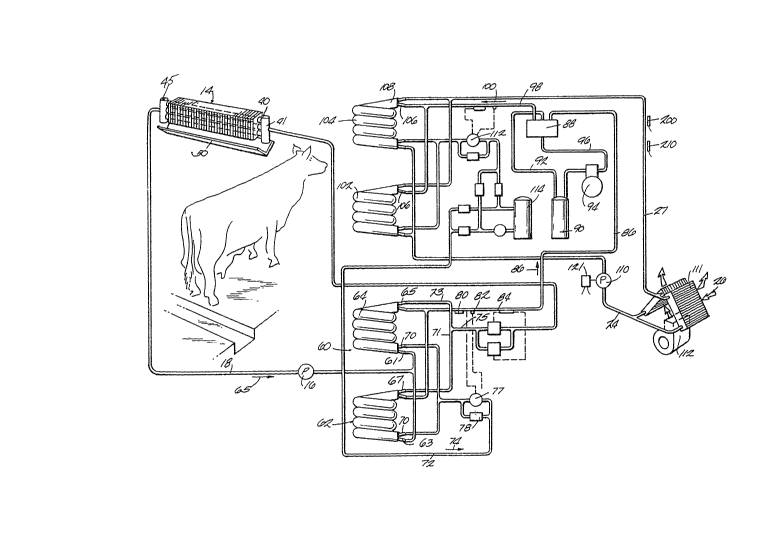
In the drawings, Fig. 1 shows a house 10
and a barn 12. A plurality of heat exchangers 14
- are arranged over the stalls of dairy cows in the
barn 12. The heat from the cows heats the working
fluid circulating in the heat exchangers. The heat
transfer fluid which has absorbed heat is conveyed by
pum~ 16 through conduit 18 to a heat pump system
generally designated 17. The heat pump system 17
upgrades the heat of the transfer fluid circulating
through conduit 18 in a first closed loop water
cir~ulating system. ~he compressor 94 upgxades the
heat from the first system and a second closed loop
circulation system is employad including conduits 24
and 27 to convey heated fiuid through a building or
room heat exchanger 26. The heat exchanger 26 re-
leases the heat into the interior 30 of the building
1~ during the heating cycle.
When using the system in the air condition-
ing mode to cool the house, an outdoor heat exchanger
31 may be e~ployed ~hich removes heat ro~ the txans-
fer fluid circulated through conduits 18 and 19 from
the house. Usually the heat exchanger 30 is not re-
quire~
~S More specifically, and referring again to tlle
hea~ e~changers 14 as iilustrated in Fig. 2, the heat
exchangers 14 ea-h include a plurality oE hori~on~ally
exten~ing inned condu~ts 40 arrangad in a ver~ical
plane and connected in parallel by headers 41. The
individual units 14 can be connected in series, as
illustrated in Fig. 1, or in parallel. The heat ex-
changPrs 14 are desirably positioned over each stall or
in spacefl l~cations in a ree stall dairy barn~ The
banks of fins and conduits are located over a drip
trough 5G 50 that the moisture will drip in'o a gutt~
ZZl~
-- 5 --
or trough 50 for disposal. The heat exchangers are
positioned so that they pick up the convected heated
air above the cows and the airt with heat removed,
flows downwardly by gravity around the cow.
S The heated transf r fluid is conveyed by
conduit 18 to a first transfer fluid-refrigerant heat
exchange assembly 60 which includes first and second
conduit coil sections 62, 64O The heat exchange
coils 62 and 64 have transfer fluid inputs 61, 63
connected in parallel to the conduit 18. During the
building heating cycle the flow of the heated fluid
goes in the direction of arrow 65 into the inlets 61,
63 of each heat exchanger section 62 and 64. The
heat exchangers 62 and 64 have concentrically located
lS inside and outside 50ils with the conduit 18 connected
to the outside coil which can be 1-1/4 inch plastic
tubing and which carries the transfer fluid pumped
from the barn. The inside Freon conduit 70 in each
coil is preferably a 3/4 inch copper nickel tubing. The
heat exchanger is si~ed an overall 26 feet per ton of
capacity as compared with typical and conventiona]. heat
exchanger ratio of 11 feet per ton, as hereinafter
discussed.
The outlets 65, 67 of the transfer fluid
conduit are connected in parallel to return line 75
by conduits 71, 73. Re urn line 75 returns the trans-
fer fluid to the barn heat exchanger 14 or other heat
source. The division of flow of the transfer fluid
colls in heat exchange assembly 60 results in reducinq
the velocity of the transfer fluid flow caused by circu-
lation of pump 15, which thus causes an increase in
residence time of the barn transfer fluid in heat ex-
change relationship in the coil assembly 60. Because
of the increased residence time, more heat can be
-- 6 --
transferred to the Freonv Similarly, the divided
Freon coil increases the residence time of the Freon
by reducing the velocity o~ the Freon. The increased
residence ime of the ~'reon results in elevating the
temperature of the Freon above that which would result
from a lesser residence time in the heat exchange
coils. The increased temperature increment also
causes greater expansion of the Freon and higher Freon
pressures delivered to the co~pressor. Hence the Freon
introduced into the compressor has ~ higher temperature
and prsssure than that introduced with the undivided
coil. This reduces the amount of electrical energy
required to operate the compressor and circulation
pumps, thus increasing the efficiency over prior art
heat pump constructions.
For example, with an undivided heat exchange
coil the Freon entering the coil may have a pressure of
40 psig and that exiting the ooil a pressure of 45 p~ig.
The temperature of the entering Freon may be 18 F
and the exit temperature may be 28 F. With the
divided coil asse~bly 60, as shown in Fig. 2, the
pressure increase may be for example from 40 psi to 49
to 50 psi and the temperature increase from 18 F to
38 ~. To obtain a super heat of 20 F with an un-
divided prior art coil, an increase in compre~sorcapacity and increase in circulation pump capacity
would be required.
Based on actual tests with entering wat~r
tempe~:atures of 50 F in a single heat exchanger coil
v9. divided heat exchanger, the output with the singLe
heat exchanger coil was 64,300 btuh and a COP of 3.61
and with a divided coil the output was 81,250 btuh and
a significantly imp.o~ed COP of 4.9.
These benefics cannot be achieved by merely
increa~ing the length o~ an ~ndivided heat exchange
coil. The length of the conduit or coil through which
Freon is circulated has to be matched with the com-
pressor capacity or design back pressure for that com-
pressor. A certain minimum pressure is required to
S achieve return of all of the compressor oil which gets
into the Freon pl~mbing system. Increasing khe length
of the coil would result in increasing the total pressure
drop and require a larger compressor to produce a
lesser heat output which would decrease rather than
increase the COP. Also, a larger circulating pump
would be required. Dividing the heat exchange coil
rgduces v810city and causes only a minimal pressure
drop. Furthermore, the total pressure drop through
the divided coil is less than that through a single
coil of the same length because of the paralleling o~
flow and the reduction of the length of conduit the
fluids must flow through. This minimization of pressure
drop can enable use of even greater lengths of conduit
to increase heat exchange between the transfer fluid
and ~reon without causing an imbalance between com-
pressor capacity and tot~l conduit length. For example,
a conduit length of 26 to 28 feet per ton of compressor
capacity is typically employed in commercial embodiments
of the invention. Various prior axt units with an
undivided coil employ 11 to 18 ~eet per ton. The divided
heat exchangers and the reduction of pressure drop
otherwise encountered also reduces the size of the
circulatory pump required to move the transfer fluid
betwee~ the input and output heat exchangers. This
reduces the electrical power consumption of the total
system.
During the building heating cycle ~Fig. 2),
the liquid Freon is introduced into the heat ex-
changers through conduit 72, with the Freon flowing
in the direction of the ~rrow 74. The Freon flow i~
resulated b-~ an exparlsion va],ve 77 and one-way valve
78. The expansion valve has r~ temperature sensor
control 80 and a tap 82 in line 84. The tap ~2
senses pressure and equali~es the system after shut-
down. Duriny tlle heating cycle 9 the output Erom theheat excharlgers 52 and 6A is in the form o~ gaseous
Freon which i~ conveyed by conduit 84 in the clirec~ion
of arrow 86 to a reversinc3 valve 88. In the heating
mode the gaseous Freon corlventicnally goes thrc~ugh a
suctic-~n accumlllator 90 via conduit 92 and then to a
compressor 94 where the temperature and pressure of
the gas is xaised. The heated Freon leaves ~he heat
pump t~hrou~h concluit 96 and goes through the revers-
ing valve 88, throuyh conclui~ ~8 in thQ direction cf
arrow 100, where it is lntroduced into a second divided
h~a~ exchatlger asGe~bl~,~ having two coils 102 and 104.
Thi~ heat exchanger has similar dividecl coils with an
inner Fxeon co~l and an out~r wa'er-alcohol coil.
The hea~ecl Freon is intro~ucecl to the inner coil 106
in which the E'reon giv9s OLf its heat to the water
based .rall~f~r flu;.~ contai.ed in the outer coils 108.
The hea~ ~ransfer flui.d is m~ed through th~ wate~
co,.ls 108 b~ a pump 110 il~ line 24 which continuously
~irc~la~.es t:~le water du~inc3 the hea~ing moce througl-.
a water--to-air heat exchanger 26 anâ lines 24, 27
whic~, have a Einne~ co~duit 111 w.ith a blower 112
wrli.cl~ OWS ~ir through tl~e heated I ins into t};e room.
Tl~ reell soes thrc)ugh the recei~Je.r 114 a~.d .llen
th2 expan6ion valve 77 an~ is returned to t,he he~.t
exchanger~ 6~2 and 64 ~.~ia lin~ or ccnduit 7?. where it:
a~ain is gasi~ied.
The heating tnode is controlled b~ a roor~
thermos~at 123 and associated switche.s which contrG
~l7~ ~,ump llQ and heat e~char.ger ~lowers 112. The roo~l
; ~ 35 therm~stat puts thc revelsing valve it. the heating mode.
Zl~
_ 9 _
If the room thermostat calls for heat, pump 110 and
blower 112 are energized and thermostat 200 is enabled.
If the temperature in the water line 27 is less than
the set point of for example 86 F, the compressor
94 will be energized. The pump 16 in the barn circuit
is connected by a circuit so that it is simultaneously
energized with the compressor. The compressor will
run until the high sstting for thermostat 2no ~ of
for instance 90 F, is sensed and the circulating
pump 16 will be shut down. However, the circulating
pump 110 and blower 112 will continue to operate and
int-oduce heat into the room even though the compressor
is not drawing power until the selected room temperature
is attained and sensed by thermostat 121. This signi-
ficantly increases the COP.
Cooling Mode
The room thermostat will switch the revers-
ing valve to the cooling cycle when the room air
conditioning unit is switched to air condition-
ing mode. If the room thermostat 121 calls for cooling,the circulating pump 110 and blower 112 will be energized.
A thermostat and hulb 210 control temperature o ~he
transfer fluid in condui~ 109. If the temperature in
conduit 27 is above a set point of for example 40 F,
the compxessor 94 will be energized and the compressor
94 will run until the 40 F is sensed in conduit 27
and the compressor 94 and airculating pump 16 are de-
energized. The blower 112 and pump 110, however, will
co~tinue to operate until the temperature of the room
as sensed by ~hermostat 121 drops to the control
setting of thermostat 121 and de-energizes pump 110
and blower 112.
In the cooling mode, the pump 110 circulates
transfer f]uid through the heat exchangers 102 and 104.
Heat is picked up in the building by the transfer
- 10 -
fluid and transferred to the Freon and the exchangers
].02 and ].04 and the Freon yoes to the compressor to
increase its heat and pressur~. Freon then travels to
the source water heat exchangers 62 and 64 where it
releases its heat into the source water which is con-
veyecl by pwnp 16 to the barn heat exchangers. The
Freon flow route i.s illustrated in Fig. 2 by broken
arrows for the cooling mode.
In the cooling mode, the heat exchanger 30
can be optionally used, but tests indicate that it is
not nec~ssary. A valve 120 in li.ne 19 can be employe~
to prevent circu.lation through the heat ~xchangers 14
in the barn but provide circulation of the transfer
fluid throuqh the outside heat exchanger 30 where
buildlng heat is released as the blower removes heat
from the transfer fluid.
The adva~tages obt.~ined using the divided and
para'lel :~!ow .,or the heat exchanyers 60, 62 are a].so
obt.~ined wi~h the heat ~cchangers 14. The use of the
di~ided ~low m.inimizes the pressure drop through each
heat xchan~et.~ 14 and increases the residence time of
the ~ransfe.r f.uid i.n the exchanser. A preferred
embodiment of the heat exchangers 14 would .include
hea~ers hav~.ng an inside diameter of 1-1/2 inches with
conduit5 of inside diameter of 1/2 inch. Tne fins each
consist of a single apartured plate with conduiis 40
extendillg through the aper~ures. The fins 43 dasirably
: hava a heisht o~ lQ inches anc~ wi.dth of at least 1 incn.
Bi~hi, ccnduits 40 .in sach heat e~changer has worked well.
30 :~n ail~ vent 45 and ~he to~ o a heade.r 41 assists in
ini.ti.al.ly ~ill.i.ng the heat exohanger wit.h transi-.er fiuid.
The use of water-methano:l. rather than e~h~Lene
~gl~col also requires a pump of less capacity, an~l a
smai..Ler Inotor ~ecatlse of the les.se.r ~-iscosity of l:h~
water-methanol mlx.
:
.