Note: Descriptions are shown in the official language in which they were submitted.
iZ9Z9"6
Title: VENEER LATHES HAVING VENEER THICKNESS SENSOR ~ND
THICKNESS CONTROL
This invention relates to lathes for making wood
veneer, and more particularly to such lathes in combination
with means to measure the thickness of the veneer as it
is cut in the form of a ribbon from the log. The signals
derived from such measurement are used to contLol the veneer
thickness. The invention also concerns novel control means
for adjustably positioning and controllably moving the peeling
knife of a lathe.
Lathes are used to cut veneer, in the form of
a ribbon, from a wood log or block as the block is rotated.
Typically lathes include an arrangement for rotating the
wood block, a knife and a pressure bar, and may be either
a spindle ox spindleless type. In the spindle type there
are two axially spaced head stocks that support thé log
and at least one head stock is driven for rotating the wood
block. The spindleless type lathe typically has three parallel
rollers that hold the wood block captive and at least one
of such rollers is driven to rotate the block. In either
type an adjustably movable knife is used to peel a ribbon
of veneer from the block as the block is rotated. In any
veneer forming apparatus the principal objective is to produce
a ribbon of veneer that is of uniform and precise thickness.
;,' Veneer must meet certain minimum quality standards
and the thickness must be within a few thousands of an inch
, of the average. This precise thickness is nece,ssary for
~z`~
the veneer to accept sufficient glue with a roll type spreader
or to prevent panel rejection because of being too thin or to
avoid excessive sanding losses. Veneer must be strong enough
to avoid breakage during handling, and loose enough to be
handled by automatic equipment, yet smooth enough to ensure
proper glue distribution at the glue spreader. Multi layers of
veneer are often laminated together to produce a panel product
and uniformity of veneer thickness yields panels that are
uniform.
The actual yield and qualit-; of veneer is dependent
upon lathe related variables, and as far as veneer quality i3
concerned, control is required for variable parameters such as
smoothness, tightness and thickness variability.
With a view to accompllshing the obJective of
quality control, most lathes use a nose bar in assoclation wlth
the knife.
Veneer thickness control ls the subject of United
States Patent No. 4,392,519, lssued July 12, 1983 to H.B.
Calvert, which discloses a nose bar and peeling knife assembly
wherein the pitch angle of the peeling ~nife is varied in
response to knife deflection. A sensor mounted in the knife
holder is used to detect the direction and amplitude of lateral
! deflection of the knife edge from a conditlon of substantial
equilibrium during veneer peeling. If the deflection of the
knlfe is towards the block the knife i~ said to be "leading",
1~9Z~
-- 3 --
and conversely, if the knife is deflected away from the
workpiece, it is undergoing "heeling". A leading ~nife usually
causes the knife and log to vibrate and the lathe will then
produce a corrugated veneer of irregular thickness. A heeling
knife tends to move in and out of the log producing alternately
thick and thin veneer. A strain guage sensor detects the
direction and amplitude of deflection of the knife relative to
the knife support bar and from a corresponding signal that is
generated a s~gnal responsive controller causes the knife,
which is either in a leading or heeling condition, to return to
its optimum pitch angle condition. ~ithout deflection sen~ing
and controlling means, the pitch angle (being the angle between
a horizontal plane and the plane of the cutting edge of the
peellng knife faclng the block) will vary from it3 pre-
established fietting.
The knife conventionally is guided along curved
pitch tracks, or by inclined rails as in the Calvert patent, as
it moves into the block so that the pre-established pltch angle
is caused to decrease as the diamter of the block being peeled
-decreases. The purpose of this is to maintain as close as
possible the optimum pitch angle.
In the Calvert form of construction, the signal from
the strain guage, which detects blade deflection, is used to
effect a correction to the pitch angle as it follows along lts
guide tracks, 80 as to maintain the knife in approximate
balance, and which is achieved by varying the angle of the
1~9Z~26
inclined rails in response to the signal.
Because Calvert has located the strain guage on the
cuttlng knife holder and downstream of the cutting edge of the
peeling knife, it iq susceptable to malfunctioning because of
debris accumulating in the area of the strain guage. Because
of such location the strain guage is also exposed to the
deleterious effect of steam and water.
The present invention, like Calvert discussed above,
uses a sensor that co-acts with the knife, but unli~e Calvert
provides a direct measurement of the veneer thickness as the
veneer is being peeled from the log. The novel sensor
arrangement of this lnvention can be utili~ed with known pitch
angle ad~uRtment means ~uch as hitherto taught by Calvert in
the aforementioned United Stateq Patent, or variable length
cylinder méans as disclosed herein. In an extremely simple
appllcation the sensor can be used merely to measure the
thickness of the veneer or for example the start up of a run
and if any change is necessary it can be done by manual
ad~ustment.
In the Calvert apparatus, deflection of the cutting
knife relative to the structure on which the cutting knife is
mounted is monitored and this provides perhaps in one sense an
indication of veneer thickness, i.e, thicker or thinner than
normal, because what i8 being ~ensed i~ whether the knife i8 a
heeling or leading knife, or in equilibrium. In accordance
129Z~26
with the present;invention, a direct measurement of the veneer
thickness is sensed by continuously monitoring the relative
position of the peeling knife and the lathe nose bar. This is
achieved by locating the sensor means so that it is carried by
or otherwise associated with the nose bar ltself, and so
positioned that a signal from the sensor can co-act with the
knife (e.g. being reflected therefrom), whereby blade movement
relative to the nose bar is directly measured and such
measurement is a direct function of changes in the thickness of
the veneer being peeled. This sensor is normally located in
reflective relationship to a major plane of the cutting knife
(preferrably closely ad~acent the knife's cutting edge). A
commercially available sensor suitable for such purpose is the
Kaman Di placement Measuring System.
As the Qen~or i5 ~paced from the peellng knlfe and
at no t~me is ln direct contact with the ~nife, its operation
is not adversely affected by the hostile environment resulting
from steam, water and debrls encountered during veneer
production. Further, the sensor being on the pressure or nose
bar permits using the invention on both conventional and
"spindless" veneer lathes.
In accordance with the present invention the lathe,
with the veneer thic~ness sensor, can have a solid, non-
rotating, elongate nose bar, which nose bar has been
traditional ln the industry, or a rotatable tdriven or ldler)
pressure roller whlch displays all of the attrlbutes of a
12~Z~26
conventional non-rotating nose bar, but provides greater
support to the bloc~.
In addition to the above features, where a pressure
roller i8 used as a nose bar, and whether or not the pressure
roller is used on a conventional or spindless lathe, the
pressure roller itself can it3elf advantageously include a
plurality of knife~ e projections for incising or tenderi~ing
the veneer.
In accordance with a further aspect of the present
invention there is provided veneer lathes having log and/or
knife peeling position adjusting means and which are responsive
to a veneer thickness sensor.
In accordance with a further aspect of the present
invention there i8 provided in a veneer lathe of the type
lncludlng means for ~upporting a bolt of wood and rotating such
bolt about itc longitudinal axis and a veneer peeling knife and
pressure nose bar disposed in a predetermined spaced
relationship relatlve to one another, said peeling knife and
pressure nose bar being supported on a movable carriage for
peeling veneer in ribbon-form from the outside of said bolt as
the latter is rotated, the improvement compri~ing sensor means
carried by said nose bar and co-acting with said knife to
detect variations in said predetermined spacing of the peeling
knife and nose bar and providing output signals in response and
proportioned to such variations.
In accordance with a further aspect of the present
.
129Z9Z6
invention there,is provided a veneer lathe comprising
~ a) a rigid frame structure having head stocks for
carrying and rotating a log to be peeled into a ribbon of
veneer;
(b) a nose bar and peeling knife mounted in
predetermined spaced relationship relative to one another on a
carriage;
(c) means reciprocally mounting said carriage on
said frame structure for movement toward and away from said
log;
~d) power means for moving sald carriage toward
said log at a predetermined rate to peel a ribbon of veneer
from the log as it 18 rotated;
(e~ means pivotally mounting said carriage for
movement about an axis parallel to the axis of rotation of the
log for permitting ad~ustlng the knife pitch angle;
(f) power means for selectively pivoting said
carriage; and
(g) means mounting said carriage permitting
movement of the same to selectively vary the gap between the
. knife tip and point of contact of the nose bar.. with the log.
In accordance wlth a stlll further aspect of the
present lnvention there i5 provlded a veneer lathe o the type
including means for supporting and rotating a bolt of wood
about its longitudlnal axis and a veneer pèeling knife and
pressure nose bar assembly having a predetermined flxed spaclng
l~Z9Z6
- 8 -
therebetween and.which is supported on a movable carriage for
peeling veneer in ribbon form fromthe outside of said bolt as
the latter is rotated, the improvement comprising sensor means
carried b~ said nose bar and operative to detect and provide an
output signal in response to variations in said predetermined
fixed spacing of the ~nife and nose bar and magnitude of such
variation and means for adjustably repositioning the peeling
knife in response to commands from a controller acting in
response to signals from said sensor means.
The invention is illustrated by way of example in
the accompanying drawings wherein:
Figure 1 ls a schematic cross-sectional view of a
lathe with a conventional rigid nose bar and peeling ~nife
including a ~nife position ad~usting means provided in
accordance with the present invention;
Figure 2 is similar to Figure 1 but where the nose
bar is a roller type;
Figure 2A is a partial view similar to Figure 2
illustrating a roller nose bar with incising teeth;
Figure 3 is an enlarged, partial cross-sectional,
view of the lathe of Figure 1 illustrating a veneer thickness
sensor mounted on the nose bar;
Figure 4 iq an enlarged partial cross-sectional
view, similar to Figure 3, of the lathe shown in Figures 2 or 3
Z~
- 9 -
illustrating the,sensor mounted on a support for the roller
nose bar;
Figure 5 ls a diagrammatic cross-sectional view of a
splndleless lathe with a veneer thic~ness sensor mounted on the
support of one of the rollers;
Figure 5A is a view similar to Fig. 2A but
illustrating a modified mounting for adjusting and controlling
the knife position; and
Figure 6 is a block diagram of the lathe veneer
thickness control system of the present invention actuated by a
veneer thic~ness sensor.
Tn Figure 1 there i9 illustrated ln partial cross-
section a spindle type lathe where, in a conventional manner, a
log or wood block is supported between and on a pair of
rotatably mounted chucks at least one of whlch i8 driven to
rotate the log about an a~is designated X. A knife 6 is
presented to the log and peels therefrom a ribbon 1 of veneer
as the log rotates. A nose bar 5 detachably mounted (as by
clamps) on a supporting rigid structure SA bears against the
outer surface of the log slightly upstream from the cutting tip
6A of the peellng knife 6. The knlfe 6 i9 mounted on a knife
holder 6B. The knife holder 6B and nose bar support 5A is a
rigid assembly pivotally mounted on the carriage 2. Pivotal
movement of the assembly is about the tip of the blade. There
12~2~"6
-- 10 --
have been various studies on the effect of varying lathe
rela1:ed parameters on quality of the veneer, such as relative
posi1:ioning of the nose bar and knife, and two which might be
mentioned for those wanting further information are: (a) a
report in the Forest Products Journal, October 1966, Volume 16,
No. lO, entitled "Effects of Hori-ontal Roller Bar Openings and
Quality of Rotary Cut Southern Pine and Yellow Poplar Veneer",
by J.F. Lut~ and R.A. Pat~er, and (b) a report in Wood 5cience,
January 1980, Volume 12, No. 3, entitled "Effect of Four Foot
Lathe Parameters on Veneer Yield and Quality Using Response
Serv~ce Analysis", by J.R.T. Haley, W.P. Hancock and ~.G.
Warren.
One of the main ad~ustments or variable~ in a lathe
i8 the pitch o~ the knife or the knife angle which must be
varied depending upon the kind of wood and the thickness of
veneer being produced, and furthermore must be varied as the
diameter of the log decreases and the veneer is peeled away
from the log. To accommodate the latter, and as previously
mentioned, the knife carriage conventionally has been mounted
on curved rails or tilted by a cam action during movement, as
is the case with the structure illustrated in Figure 2 of
Calvert's aforementloned Unlted States Patent No. 4,392,519.
In addition to changing the pitch angle, the kn~fe ls mounted
on a carriage movable laterally in a direction toward and away
from the spindle axis.
With respect to the present apparatus carriage 2 i~
lZ9;~926
-- 11 --
reciprocally movable in a hori~ontal plane to the left and
right (double headed arrow A) as viewed in Figure 1 by one or
more hydraulic, elëctrohidraulic (or pneumatic) cylinder units
lA. The carriage unit 2 can be raised and lowered in a
vertical direction (double headed arrow B) by a further
hydraulic cylinder (or pneumatic) cylinder unit lB attached at
one end to the fixed structure 5 and the other end by pivot pin
7B to the carriage 2.
- The knife carriage 2 is provided with both
reciprocal and vertical movement. In addition to this, the
knife and nose bar i5 movably mounted on the carriage for
movement in an arcuate path (double headed arrow C) about an
axls parallel to the axis of rotation X of the log 4 for
varying the knife pitch angle. This arcuate movement is
effected by a hydraulic cylinder unit lC attached at one end as
by a bar Bl to sllde on frame structure S, and at the other end
by a pivot pin 7C to the strùcture that carries the nose bar
and cutting knife. The bar Bl is movable with the carriage
structure 2.
From the foregoing, it can be seen the hydraulic
cyllnders lA, lB and lC adjustably control movement and
variable positioning of the peeling knife 6 relative to the log
or wood block w~ich remainq ln a fixed position. The log
during its rotation is further supported by a back up-roll 3 ln
a conventional manner, and which ls movable and in pressural
engagement with the log. The hydraulic cylinders 1~, lB and lC
12a~26
- 12 -
are each of the electro-h-~draulic type recently comlng into use
for controlling machine operations. These servoactuators move
loadc~ at high speed with high accuracy and they permit quick
changes in machine operation. There are a number of different
electro-hydraulic actuators with various feedback systems that
may be either mechanical or electrical or a combination
thereof. The system~ vary in accuracy, dependability and
complexity, and not all are suited for every application. For
the present application, the method of feedback control is
knowns as the *Tempasonic LTD which is a linear actuator
manufactured by a number of companies, including Aeroqu~p
Corporation, Moog Inc , and Parker, Hannifin Corp.. The
tranc~ducer hac~ no moving parts and thus wear i8 not a problem.
It ~s fairly tolerant of vibratlon and shock loads, and has a
po81 tioning accuracy of .001 to .003 inches.
The lathe system lllustrated in Figure 2 is
essentially the same as in Figure 1, except for the nose bar.
In the lathe of Figure 2 the nose bar is what is referred to as
a "big bar" and conClists of a roller 58 mounted for rotation on
a rigid nose bar of mounting structure 5A. The lathe is a
spindle type lathe with a roller nose bar, the nose bar being
movable along with the cutting knife and therefore somewhat
different from the roller nose bar in a centreless lathe, as
disclosed in United States Patent No. 4,335,764, issued June
22, 1982 to Charles J. Schmidt.
~ Trade Mark
lZ9~26
- 13 -
Figure 2A illustrates a roller nose bar type lathe
of Figure 2 but where the roller designated 5B' has ~nife like
pro~ections on the peripheral surface for inci~ing the wood
prior to peeling the veneer lA from the log 4.
In each of the lathes illustrated in Figures 1, 2
and 2A there is a sensor mounted in such a manner as to
determine any deviation or change in positioning of the lathe
knife 6 relative to the nose bar. This, by appropriate
calibration, gives a direct reading of the thic~ness of the
veneer belng peeled.
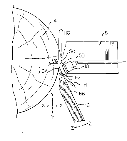
In Figure 3, which is an enlarged cross-sectional
view of the nose bar and log for the lathe of Figure 1, a
~ensor 10 is mounted in the nose bar 5 at a location downstream
from the tip 5C of the nose bar that engages the log 4. The
no~e bar, downstream from the log engaging tip portion 5C, is
recessed so as to provide an exit gap designated EG, at the
back face 6B of the knife which is greater than the horizontal
gap designated HG between the nose bar tip 5C and the leading
cutting edge 6A of the knife. This exit gap EG i~ greater than
: the thickness of the veneer designated TH allowing for free
f low escape of the veneer as it is peeled from the log.
The sensor 10, in the recessed face 5D of the nose
bar, i8 a transducer such as model type KD-2~10-6U manufactured
by Kaman Instrumentation Corporation of Colorado Springs,
Colorada which serves to continuously measure in electrical
lmpulsQ form, in a manner known, the distance and any variation
~292~2~;
- 14 -
in the distance between the sensor 10 and the opposed bac~-
face designated 6B of the cutting ~nife G. As will be clearly
evident from Figure 3, the sensor 10 is located in close
proximity or viclnity of the tip 6A of the ~nife, and thus any
deviation of the knife from its designated or set position is
picked up immediately that such deviation occurs. This allows
for implementing corrective immediate action should it be
required. The operation of the sensor or transducer 10 is
unaffected by the presence and movement of the veneer sheet 1
between the sensor and the cutting blade.
The nose bar illustrated in the lathe of Figre 2 is
a roller 5B having a central shaft 20 (Figure 4) ~ournalled by
6uitable mean~ at oppo~ed end~ on bearings on the no~e bar
~upport structure 5A and i5 further supported by a center
bearing mid-way along the length of the roll with such bearing
being carried by a ~upport 22. Mounted on the support 22 is a
sensor 10 spaced a selected distance Y from the rear face 6B of
the peeling knife 6. The tip 6A of the peeling knife is spaced
from the contact point of the roller with the log providing a
horizontal gap HG which is slightly less than the distance
between the roller and the rear face 6B of the cutting knife.
The positlonlng of the sensor, relative to the rear face 6B of
the blade, i5 co-related to the horizontal gap HG and thereby
provides a direct reading, through ~uitable calibration, of the
thickness of the veneer being peeled, and any deviation from
that thic~ness provides a ~ignal in the form of electrlcal
12~2~26
-- 15 --
impulses conducted by way of a wire 30 to a suitable controller
rendering commands to actuate cylinders designated in Figures 1
and 7. as lA, lB and/or lC.
The pressure roller 5B, depending upon its
appllcation, can vary in diamter from about 1 inch to about 6
inches, and is preferably within the range of 4 to 6 inches.
Further, and again depending upon its application, the pressure
roller may simply be an idler, or alternatively a driven
roller. Also, the pressure as for example, roller 5~' can be
provided with a plurality of cutting teeth about its peripheral
~urface for tenderizing or incising the block, and hence the
reaultant peeled veneer.
The lathes lllustrated in the foregoing embodiments
are of the spindle type in which the log i5 located between and
carrled by end plates or chucks that are rotated about a
predetermined axis of rotation. In such lathes it is also
known to uses additional rolls as idlers or powered to engage
and support the log duriny peeling
Figure 5 is a basic sectional view of a spindleles~
or centerless lathe as referred to in the aforementioned United
States Patent No. 4,335,~64, and which in turn refer~ to United
States Patent Nos. 1,951,834 and 4,073,326, as disclosing
centerless veneer lathes.
The centerless lathe conventionally consists of
three parallel rollers, one of which is fixed ln position, and
the other two movable relative thereto for receiving and
12~Z~2~i
holding captive a log. One or more of the rollers are driven
to rotate the log, and one or more of the rollers can be
provided with incising teeth to tenderi~e or incise the veneer.
Referring to Figure 5 there is illustrated a first
roll 5B of the type illustrated in Figure 4, having mounted
thereon and carrying therewith a sensor lo, roller 5B being in
a fixed location and carried by a structure designated 50. Two
further rollers designated Sl and 52 are mounted on structure~
carried by the piston rod of respective Tempasonic* hydraulic
cylinder units lD and lE. These hydraulic cylinders lD and lE
are fixed to the mounting structure 50. A further Tempasonic*
cylinder lF is anchored to the support structure 50 and has a
pi~ton rod connected to the carriage structure 53 having the
peellng knlfe 6 reclprocally mounted thereon. The peeling
knife 6 is controllably moved horizontally, as viewed in Figure
5, by a hydraulic Tempasonic* cylinder lG to change selectively
a gap designated G.that corresponds to the vertical gag VG of
Figure 3.
From this embodiment it is clearly ev~dent log
supporting rollers 51 and 52 (at least one of which may be
driven) are movable toward and away from roller 5B, the three
rollers holding captive a log and rotating the same during
peeling of the veneer. The peeling knlfe 6 is controllably
varied in pitch by actuation of the hydraulic cylinder lF
(pivoting being about pin 5A) and the gap G, iQ varied by ..
Trade Mark
lZ9Z926
actuation of the hydraul~c cylinder lG. Logs to be peeled are
infed from a bed 60 on the support structure 50, and which has
and inclined portion 61 directed downwardly to the gap between
roller 52 and roller 5B.
In the Figure 5 embodiment the veneer thickness can
be modified or controlled by actuating cylinder unit G to move
knife 6 into or out of the cut, by actuating cylinder unit lF
to pivot the ~nife support frame 53 (pivot of rotation being
the knife tip) and/or actuation of cylinder units lD and lE
varying the roll position3 and thus changing the angle at which
the block is presened to the knife.
Figure 5A illustrates an alternative to the
embodiments of Figures 1, 2 and 2A where the cuttlng knife i8
fixedly ecured to the knife holder. In Figure 5A the peeling
knife 6 i5 reciprocally mounted on the knife holder for
movement along a path parallel to arrow A-A. The direction of
path A-A relative to the log, the location of the knife and/or
the pitch of the knife can be chosen as may be required to give
the desired thickness control by moving the knife along the
predetermined path. Movement of the knife 6 is effected by a
~Tempo~onic cylinder unit ~0 mounted on the knife holder 71.
Log L is rotatably supported between a pair of end plates (not
shown) and a roller nose bar 72 is ~ournalled on a rigid bar ~3
and engaged by support rollers 74. The knife 6 is reciprocally
mounted in any convenient manner.
~ Trade Mark