Note: Descriptions are shown in the official language in which they were submitted.
3~
CLUTCH MECHP~ISM
Backaround of the Invention
The ad~ent of microprocessor logic znd its ability
to operate with Ye~y low power requirements has
spawned a lar~e number of applications to remote
operations wherein it is impractical to supply other
- 05 than bat~ery powerO In such operations, it is
essential to conser~e power draw and thereby extend
the life o~ ~he decision capability o~ the
microprocessor.
One such application has been found in the
reprogrammable combination electronic loc~. ~he. use
-~ of a-battery-powered microprocessor eliminates the
need ~or hard wixing doors and further allows such
locks ~o be utilized in remote locations where power
is not readily available. A problem in the past has
15 : been the amount_of power re¢uired to engage the
lockin~ mechanism once the microprocessor has decided
that it is appropriate to do so.
U.S. Patent No. 4,526,256 discloses a clutch
mechanism o~ which this invention may be considered an
improvement thereof.
Su~marv of the_Invention
The present invention comprises a clutch mechanism
which requires extremely low current draw by
utilizing, in par~, mechanically applied power to
assist in Pngagement of the clutch mechanism and a
novel combination of timed function motion sensor and
latching solenoid set and released inter~erenca
shutter. The object of the invention is to provide a
. ,, _ . , , ,, .. . ~. , , j . .. ,_.. _,_ ___, . _ ._ _ _. _,_ ~ __ _ . _ __ _ _ .. ... .. _ . _ . .. . .. _ . . . ... .
. .... . . . .. . ... . . . . ....
~3~o~
clutch mechanism which requires minimal current drain
for operation onc~ a decisîonal command to operate the
clutch is recei~ed.
; . A further object of the invention is to provide a
05 simple~ reliable and economical clutch mechanism. It
: is a further object of the invention to provide a
clutch mechanism which may be utilized in combination
with a micrcprocessor logic circuit in many
applications~
' Yet a ~urther object is to provide a clutch
- mechanism for use with a combination electric lock
which may be battery powered.
- .? These and other objects are obtained in a-clutch
mechanism, for an electronic loc~ or the like,
comprising: a first rotary clutch element, mcunted
for ~ree ratation about, and relative to, a spindle,
having a first jaw element; a second clutch element,
mounted for translation along, and~rotation in common
; . '' .''''with, the"'spindle,"having a second jaw element
.~ 20 engageable with the firs~ jaw element for effecting
rotation of one of the clutch elements in response to
the rotation of the other o~ the clutch elements;
. means interposed between the clutch elements normally
restraining the clutch elements in spaced apart
Z5 disposition; means for resiliently urging one of the
clutch elements to move towards the other of the
: clutch elements, in reponse to rotation of one o~ the
clutch elements to cause said ~aw elements to engage:
means for selectively preventing movement o~ the one
. . . 30 clutch element towards the other clutch element,
whereby the ~irst and second jaw elements are
~Z93~
prevented from e~fecting engagement and rotation of
the one clutch element in response to rotation of the
other clutch element; the improvement comprising: a
la~hing means in the means for sele~tive~y preventing
05 movem2nt of the one clu~ch element; timing means for
release of the latching means; and motion sensing
mea~s for alternatively releasing the latching means.
Brief Description o~ the Drawinas
. ....... FIG. 1 is an exploded view of the clutch mechanism ....
according to the present invention, as applied to.a.
10 loc~;
.FIG. 2 is a side elevational ~iew in full line
- ~ . illustration of the inne~ clutch plate, cam ~ol-lower,
follower block, bias springs, and bias arms, the
; . - -- latter shown in engagement with the inner clutch
plate, and in dashed outline the cam ~ollower and
ollower-block are shown in a cammed or displaced
disposition;
FIG. 3 is an elevational view taken from the left
hand side o~ FIG. 2 in which, however, the inner
clutch plate.is shown only in phantom; and
FIG. 4 shows an electronic schematic showing the
interrelationship between the timed latch function and
- the motion sensing ~unction o~ the present in~ention.
DescriPtion of the ~Pre~erred~Embodiment
. FIGS. 1 through 4 show a clutch mechanism
according ~o the presen~ in~ention embodied in a door
lock mechanism. Th~ door lock mechanism is intended
.3--
~32~l3
for use with a microprocessor or other logic sequence,
or decisional mechanism which would activate a
latching solenoid such as ~olenoid 15 as depicted in
FIG 1.
05 It is intended that the power requirements
necessary to opera~e solenoid 15 be minimal. It is
also intended that the clutch mechanism, which engages
the outer handle with ~he spindle, derive its energy
of operation primarily from ro~a~icn of the outer
handle. Further, it is intended that engagement o
the clutch mechanism will enable rot2tion of the lock
actuating spindle by the outer handle, The lock may
be of any convenient or conventional configuration
which utilizes a manually energized spindle ta operate
the latching mechanism.-
Referring now to FIG. 1, the clutch mechanismaccording to this invention is comprised of an outer
; clutch plate 1, which is moun~ed for rotation about a
'-' ' ;'' cylindrical~port'ion' of'an'outside spindle 7. 'In ' ~ '
mounting, the outer clutch plate 1 will not be free to
translate axia].ly along the outer spindle 7.
An outer lever handle 5 is shown attached to the
outer clutch plate 1 for rotation therewith by means
not shown. It should be understood that outer handle
5 may be manufactured as part of the outer clutch
plate 1 or attached thereto by any convenient means.
The outer clutch plate is provided with a set of
oppos2d out~r jaws 3 and an operating cam 21 disposed
on the outside periphery of the outer clutch plate 1
A coacting inner clutch plate 2 is mounted on an
inside spindle 8 of square cross section. The inner
clutch plate 2 rotates with the spindle ~ and is free
~
~Z~32~3
to translate axially along the spindle from an inner
position to an outer position wherein a coacting
female jaw me~ber ~ engages the outer jaw member 3.
It should be appreciated by on~ skilled in the art
05 that rotation of the outQr handle and outer clutch
plate will not xotate the outer spindle, and the inner
spindle will not rotate until the inner clutch plate
is mo~ed towards the outslde and the coacting jaws OL
the clutch engage. Once engaged, the inner spindle 8
may be rotated by the outer handle 5.
A coil spring 10 is.disposed about the-oute~
spindle 7.and centered..partially.:in a.recess 30 ~ormed ..
-- - in the face of the outer clutch plate 1. The purpose
..~o~ coil spring 10 is to yieldingly urge the inner
clutch plate 2 out of engagement with the outer clutch
plate 1. A mounting plate 9 forms a positioning base
for the 70ck mechanism.
FIG. 1 is an exploded ~i~w o~ the mechanism
~according~-to~~he prësent~invëntion, and it should be
appreciated that on assembly, the ~ace 31 of the outer
clutch plata 1 would be in close proximity or contact
with the outer face of the moun~ing plate 9, with the
outer clutch jaws concentric with and extending
partially into the hole 32 o~ the mcunting plate. The
2S peripheral diameter of the inner clutch plate 2 is
slightly smaller than the diameter of the hole 32 so
~ as to allow it to enter the hole to permit engagement
af the jaws.
A shutter 11 is shown mounted on mounting plate 9
by means of a shutter pin 12. The mounting allows the
shutter 11 to rotate about pin 12. A stop pin 16
fixed in and projecting outwardly from the mounting
~2932~8
plate 9, intrudes into a rectangular orifice 33 formed
in the shutter 11 to limit rotation of the shu~ter
11. As shown in FIG. 1, the shutter is in its release
or uppermost position which allows the inner clutch
05 plate to ccntac~ the outer clutch pla~e. I~ should
~urther be appreciated by one s~illed in the art that
~- the shutter may be rotated counterclockwise as shown
in FrGo 1, in which position it will par~ially block
. . hole 32 and interfere with the inner clutch plate
passing into hole 32.
~ ... . . The position o~ the shutter ll Is controll-ed by.. ...
solenoid 15. The position shown in FIG. l.is.. the.... -:
activated or release position. .A.solenoid.spring 17
urges tha shutter 11 counterclockwise to the
~- - 15 interference or-lock position wherl the solenoid~-15.is..
not activated. The solenoid plunger is connected to
the shutter 11 by means o~ a solenoid pin 14.
The mechanism which urges the inner clutch plate
towards-the outer c~utch plate is comprised of
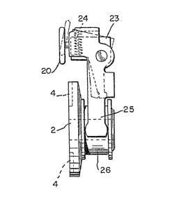
basically five parts--a cam ~ollower 20, a follower
block 23, biasing springs 24, bias arms 25, and spool
26. The af~resaid parts, in their cooperati~e
assembled relationships, are shown in FIGS. 2 and 3.
5pool 26 is attached to inner clutch plate 2 and
is ~ree to translate axially along spindle 8. Cam
~ollower 20 is provided with a cam shaft 22 which
extends into a bearing hole through cam follower 20.
The cam follower 20 may be retained by any suitable
means, such as a snap ring, on the cam shaft 22.
It should be understood that the cam sha~t 22 is
~ree to rotate in its bearing ~or the pre~erred
embodiment; however, it is not necessary ko ha~e the
. . ~ .
LZ~32~
cam follower rotate except as a means o reducing
friction to provide ease of operation.
Cam follower 20 is disposed in cam 21 and provides
an index means for handle 5 as well zs a devioe to
05 rotate ~ollower block 23 when cam follower 20 is
forced out of cam 21 and rides on the peripherzl
diameter Q~ outer clutch plate 1. Foilower block 23
is provided with a pair of bias springs 24. Only the
right hand spring is visible in FIG. 1. A- - - 10 corresponding spring is disposed on the lef~ hand-side
o~ the follower block 23.- -
~-~ Bias arms 25 are mounted for rotation abou~-the --
follower block ~3 on-a common mounting-pin 27-. With
_ ~ _ the bias springs 24 interpose~ between the following
~~ 15 block 23 and the bias arms 25, it should be obvious-to~
one skilled in the art that movement of the cam
follower and hence the follower block will result in
an urging force developed by bias springs 24 to rotate
~ ~he~bias a~ms in a clocXwise direction as viewed from
the left of FIG. l.
The follower block 23 and bias arms 25 are mounted
to the mounting plate g in a U-shaped saddle 28 by
means of the mounting pin 27 as shown. It should be
appreciated now that rotation of the handle 5 results
in the clockwise ro~ation of the bias arms which, in
turnl coact in the spool 26 to urge the inner clutch
plate towards the outer clutch plate.
; I~ should also be appreciated that when the
shutter 11 is in its inter~eriny position, relative
movement-between the follower blocX 23 and the bias
arms 25 is absorbed by the bias springs 240 This
permits rotation of the outside handle 5 without
rotation of the spindle 8 and operation of the lock.
~z~
When solenoid 15 is activated, by some activating
ffleans r shutter 11 will be rotated to a position where
its length obstructs the inner clutch plate and the
bias arms w~ll urge the inner C1ULCh plate into
05 engagement with the outer clutcn plate when the handle
is rotated. As a consequence, the inner and outer jaw
members 4 and 3 will come into mutual engagement.
~: Accordingly, further rotation of th~ handle 5 will
: cause rotation of the spindle 8. Where the spindle ~
serves as an operating element in.a..locX.,.its-rotation
:,-,,, , . , can be used to ef~ect.operation.of,.the:lock:or.its- :. ..,.~.mechanism.
... ~n.-. An,inner handle 6 directly engages spindle 8 and... .....
may be utilized to rotate the spindle directly at any
,, ,", 15 tlme without engagement o~:the clutch pl~tes.a:..-~.......
.To this point, except for the use of a latching
- sol~noid 15, the ~unction of the clutch mechanism i9
,as described in U.S. Patent 4,526,256 assigned to
2~. Schlage-~ock-Company-.-,The present invention
dramatically reduces the power demand by reducing the
time re~uired to energize the solenoid. In addition
to reduced power demand, loc]c security is improved by
providing a motion sensing means in combination with
the latching solenoid and a timing means. ~he
com~ination can be utili~ed to sense lock,function and
warn of tampering.
Referring now to FIG. 1, an electronic motion
sensing device such as optical scanner 40 is shown
conveniently mounted on mounting pla~e 9 ~y means of
rivets 44. A target 42 or.,identity code is shown
attached to the outer clutch plate 1. On assembly and
operation the optical scanner ~reads~ or senses the
--8--
~3~
passing of the target 42 in a well known mznner
through a square slot 43 cut in the mounting plate 1
for that purposeO
FIG. 4 is a schematic of the interrelated function
05 of the elements of the present invention. In the
prior art, the clutch meohanism was activated in
response to a command by the lock logic 50 ko open.
Solenoid 15 was energized ~or a convenient period of
time, for example 8 seconds, as determined.by timer
. 10 55. If the operator was not ~uick enough, he or she
~ -- . . would be timed out .and would-again need:to."~e-~ey.!! -~
- - the lock for a second function cycle--. During th-e~8-- -
~-- second cycle, the solenoid was fully energi2ed.::and--~:~~.--
drawing on the battery.
- 15 ln the present invention, the DC solenoid 15' is--
pulsed or energized for a short time only su~icient
to retract the plunger and magnetically latch it in
the open posi~ion. To accomplish thisj positive
` ~ voltage 1s applied to, for example, terminal A of the
20 solenoid 15'. At this point, timer 55 and motion
sensor or detector 40 is activated and one of two
op~ions takes place. If the lock handle is not
rotated to rotate the outer clutch plate 1, the timer
will reset the lock after a relatively longer period
of time, say 15 seconds, ~y application of positive
voltage to terminal B for a periad of time sufficient
to unlatch the solenoid. The motion detector may also
be deenergized. In the second alternative, the lock
handl2 will ~e rotated to open the lock and the motion
..... . .. 30. detector 40 will sense sufficient rotation to open the
lock and therea~ter the lock is reset again by a short
application of positive voltage to terminal B.
.. , . , , ~ _ . .. _ .. , ~ ._ _. __ __ __ _. __ . _., __ _ .... .. _. .. . . . . . . . . .. .. ....... . . ........ .
. ~
~932~
It will now be appreciated by one skilled in the
art that the amount of time reouired to have the
solenoid 17' energized has been reduced from say 8
seconds to perhaps one second or less.
05 The pre¢ence.of motion detector 40 can serve a
second ~se~ul purpose in that .if the lock handle is
rotated wit~out proper "keying" of the lock function,
an alar~ 60 may be sounded for a timed period, thus
warning occupan~s of an a~tempted en~ry.
It should be obvious to one skilled in the art .
'.!,, ,,''' ' .that n~merous..~modifications.of..the clutch.mechanism.a~s
..... ' described, and:,numerous.. other applications.. ~o.r a :_
-,... , clutch mechanism.deriving a portion.. of its.ope~ating
power from an input drive on selected command, will
"become apparent. ...I-therefore do no~.want to be
,. limited in thP' scope of my invention e~cept a,s
,claimed.
.
--10--