Note: Descriptions are shown in the official language in which they were submitted.
12'-~7,~;
The present invention relates to a system for retaining
documents such that withdrawal and replacement of the documents from
the retainer is sensed through the use of an electrical circuit and contacts
incorporated into the retainer. In a more specific example, the present
S invention relates to the protection from loss of credit cards using a so-
equipped wallet or purse.
At present, the most common retainers for documents are
file cabinets, brief cases, folders, purses and wallets. These retainers are
intended to be used for organized storage and physical protection of
documents and provide varying degrees of capacity, portability and
security. With these retainers it is however, quite common for the user
to forget to place the documents back into the retainer after use. As a
result and most commonly with respect to credit, bank transaction and
personal identification cards, the documents are left behind at point of use
where they are particularly prone to loss, theft and misuse.
There have been several previous attempts at solving this
problem. In particular, U.S. Patent No. 3,959,789 discloses a credit card
carrying case which incorporates contacts attached to the inside surfaces
of separators adapted to hold the credit card and to detect the absence of
a card. However, problems exist in this design in that the case is very
bulky and uses a single external spring clip to bias the multitude of pairs
of separator contacts together. The use of the single spring clip results
in the contact pressure of the spring clip being spread over too wide an
'~
1~93786
area thereby reducing the sensitivity of the device making the sensitivity
too low for reliable detection.
U.S. Patent No. 4,480,250 discloses a credit card carrier in
which a series of clip switches bridge from the hinge or spine of a pair
of folding flaps to common conductor strips, one strip being located on
each side flap. An alarm is triggered if the edge of any card is not held
between the assigned dip switch contacts when the flaps are folded to
overlie one another, due to the closing of a magnetic proximity switch
featured on the outboard edges of each flap. However problems exist in
this design in that the edge to edge card holding layout is inconvenient in
terms of space and area required per card. Furthermore, no facility is
considered to guide the cards into position between the clip switch
contacts or to prevent them from falling out of position. In addition, the
magnetic proximity switch is fragile, imprecise and difficult to align if the
carrier is flexible. Also, the magnetic proximity switch rnight endanger
the magnetic code strip common to most modern credit and bank cards.
U.S. Patent No. 4,652,865 discloses a credit card holder
composed of partly transparent pockets with conductive strips and/or disk-
sbaped magnetic contacts attached to the inside surfaces of the pockets in
opposed alignment. The strips or contacts detect the withdrawal of credit
cards and electricaUy activate an alarm system consisting of a battery,
buzzer and timer. In one embodiment, leaf springs are provided inside
double layered pocket walls to urge the walls and attached contacts
together. In another disdosed embodiment, the pockets are configured in
.
1~3~i'86
book leaf form or edge to edge fold-up accordion fashion. However,
problems exist in this holder in that the use of the magnetic contacts may
damage magnetic card coding provided on credit or bank cards.
Furthermore, the leaf springs positioned between pocket lining layers may
S cause bulging of the pockets and, without solid anchoring or support, may
not provide sufficient force for reliable sensor contact pressure and
function.
U.S. Patent No. 4,721,948 discloses a wallet with a credit
card holder that utilizes a flat flexible magnetic strip upon which two flat
parallel conductors are insulatedly attached. Co-attractive conductive
ferrous chips are opposingly attached to the inside of the far pocket walls
such that the near pocket walls, which over-lie the conductors, have
openings to allow the chips clearance to attract magnetically into contact
with the conductors upon withdrawal of a credit card. The chip bridges
the conductors and doses the alarm circuit. The sensor function is
completely dependant upon the magnetic attraction of the ferrous chips to
the magnetic strips. Again proUems exist in that damage to the magnetic
code provided on cards may occur due to the magnetism. Moreover, the
ferrous chip materials are sub3ect to oxidation and subsequent poor
conductivity.
It is therefore an object of the present invention to provide
a novel document retainer.
~)
lZ9378~
According to one aspect of the present invention there is
provided a document retainer comprising:
a plurality of receptacles, each of said receptacles for
receiving and holding a document therein;
S sensing means associated with each of said receptacles for
detecting the presence or absence of a document in said receptacle;
an electronic circuit responsive to said sensing means and
being energized by a power supply upon detection of a document absent
from said receptacle by said sensing means, said electronic circuit
including:
an audible alarm operable to provide an audible signal;
time delay means in communication with said audible alarm
and being operable to connect said audible alarm to said power supply
after a predetermined amount of time has elapsed after energization of
said electronic circuit; and
switch means in communication with said time delay means,
said switch means being manually actuable to reset said time delay means
to inhibit said audible alarm from sounding.
Preferably, the time delay means includes a timer which
initiates a count upon energization of the circuit and that the audible alarm
sounds once the count reaches a predetermined value. It is also preferred
that the switch means resets the timer and that the timer resumes the
count once the switch means has been actuated and subsequently released.
lZ93~86
It is also preferred that the document retainer further
includes an inaudible alarm operable to provide an inaudible signal upon
energization of the electronic circuit.
S In another aspect of the present invention there is provided
a document retainer comprising;
a receptacle having front and back walls to receive a
document;
sensing means having first and second electrical contacts
disposed in said receptacle, said contacts having a pair of juxtaposed faces
spring biased towards one another to be engageable with one another and
to establish electrical contact therebetween, said faces being maintained
in a spaced relationship by insertion of a document in said receptacle,
each of said contacts being secured in an electrically insulated manner at
one end thereof to a substrate;
said substrate maintaining said faces in alignment and
preserving said spring bias;
said receptacle front and back walls constituting guide means
for the insertion of a document in said receptacle and between said faces,
each of said walls being provided with at least one aperture therein, each
of said apertures allowing at least one of said contacts to pass
therethrough so that said faces are located in the interior of said
receptacle;
said substrate extending laterally beyond said contacts to
provide laterally spaced marginal edges for attachment of said substrate
to one of said receptacle walls adjacent opposed edges thereof to maintain
12937~6
alignment of said substrate to said receptacle and said faces within said
receptacle; and
means provided to connect operatively said contacts to an
alarm circuit to trigger said circuit upon the withdrawal of a document
S from said receptacle.
Preferably, the document retainer includes a plurality of
receptacles each operable to receive a document. It is also preferred that
the first contacts are formed on one electrically conductive plate and that
the second contacts are formed on a second electrically conducive plate
with both plates being attached to the substrate in a manner to maintain
alignment of the contacts on the plates.
l~e present document retainer provides advantages in that
alarms are initiated upon removal of documents from the retainer for a
prolonged time. This reduces the probability of loss of documents.
Moreover, the design of the document retainer facilitates placement and
removal of documents therein to ensure that the documents are seated
correctly ~or detection by the document sensing components in the
document retainer.
Preferred embodiments of the present invention will now be
described by way of example only, with reference to the appended
drawings in which:
.r~
lZ93786
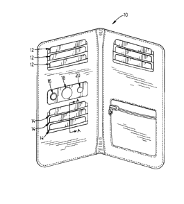
Figure 1 is a perspective view of a wallet;
Figure 2 is a perspective view of a portion of the wallet
shown in Figure l;
Figure 3 is a sectional view of Figure 1 taken along line A-
A;
Figure 4 is plan view of another portion of the wallet shown
in Figure l;
Figure S is a perspective view of the portion shown in
Figure 4;
Figure 6 is an exploded perspective view of another
embodiment of a portion of the wallet shown in Figure 2;
Figure 7 is a perspective view of the portion shown in
Figure 6;
Figure 8 is a sectional view of Figure 7 taken along line B-
lS B;
Figure 9 is a perspective view of the portion shown in
Figure 6; and
Figure 10 is an electrical schematic diagram of a portion of
the wallet shown in Figure 1.
Figure 1 shows a wallet 10 holding several credit cards 12
with each credit card being held in a separate receptacle or pocket 14.
The wallet is purchased with blank cards which are substituted for more
useful cards as required. Each receptacle is provided with a pair of
contacts which close upon the withdrawal of a card to detect the absence
of the card. Closing of any pair of contacts energizes an operationally
12937~f~
connected alarm circuit which in turn immediately energizes a warning
light 20 thereby indicating that a document is missing from a receptacle
and that batteries provided with the wallet are in working order.
A timing device in the form of a timer is provided in the
alarm circuit and is operable as is known by those of skill in the art to
commence a count to suppress the energization of an audible alarm 18 by
the batteries until the count reaches a predetermined value. The
predetermined value is selected so that the alarm circuit is suppressed for
a time period considered sufficient for a transaction to be completed. If
it is found that the transaction is lengthy a timer reset switch 16 can be
pressed and released to reset the timing device so that the audible alarm
18 is suppressed for another transaction time period. Resetting of the
alarm timer can be repeated as many times as is necessary to complete the
transaction. Reinsertion of a withdrawn document into the receptacle
reopens the contacts, which in turn results in the alarm circuit being de-
energized and the timer being automatically reset. Accordingly, the
conhcts within each receptacle function as sensors for detecting the
presence or absence of a document in each receptacle.
~0
Figure 2 shows one preferred embodiment of an assembly
50 for sensing the withdrawal of card from the receptacle in the ~etainer.
The assembly 50 includes a pair of stamped metal card contact sensor
plates 21 and æ respectively. Each sensor plate 21,22 includes a
plurality of contact segments 25,26 and 27 in echelon with the segments
on each plate being aligned. Each segment has a contact surface 24 with
lZ5~3~36
the surfaces 24 of each plate being opposed. The contact segments 25,26
and 27 protrude through retainer pocket linings and are biased to spring
into contact upon removal of any one of the cards 28, 29 and 30
respectively held therebetween.
Figure 3 shows cross-section A-A of Figure 1 and better
illustrates the pair of contact segments 26 and the manner in which they
are maintained in opposing a1ignment. As can be seen, a moulded plastic
mounting anchor or substrate 34 is positioned adjacent one end of the
sensor plates. The substrate 34 has stepped pins 36 formed thereon
including a large diameter porffion 38 and a smaller diameter poffion 42
which pass through holes formed at one end of each pair of contact
segments 25,26,27 respectively. Preferably, the sensor plates are sub-
assembled to the substrate 34 with the large diameter poffion 38 of the
pins 36 being pressed through matching holes in the sensor plate 21 and
the smaller diameter porffion 42 of the pins 36 being pressed through
matching smaller holes in the sensor plate 22. After assembly, the pins
36 are heated and flattened as shown to ensure permanent integrity. A
card 29 is shown held within the pocket lining and separating the contact
plates 21 and æ. It should be apparent to those of skill in the art that the
depth aspect of the substrate 34 is exaggerated to magnify the features.
The substrate is preferably designed to be as thin as possible to make the
retainer as thin as possible.
A pocket lining is used to isolate the sensor plates 21, 22
and to guide each card between its respective pair of contact segments.
1~37~36
Figures 4 and 5 better illustrate the pocket lining. As can be seen, the
lining is made from one pre-cut sheet of thin insulating material 48.
Rectangular holes 54 are provided through the lining 48 and allow for
protrusion of the contact segments Oll the plates 21,æ. In Figure 4, the
dashed lines 60 represent fold lines. After folding of the lining 48 as
shown in Figure 5 to define the receptacles, the bottom folds are fitted
between the respective contact segments. The four lining mounting pins
S9 on the substrate are then inserted into the corner holes of the lining 56
and the pins are heated and flattened, thereby fixing and aligning the
lining 48 with respect to the substrate 34 and contact segments. This
retainer assembly is then fitted and/or sewn into the retainer holder or
wallet after connecting the electric circuit to terminals 57 and 58 (Figure
2) extending downwardly from the sensor plates 21,22 respectively.
lS Another preferred embodiment of the retainer assembly is
shown in Figures 6 through 9. Figure 6 shows the substrate 86 in the
form of a thin flexible insulating body which is disposed between two
attached metal contact plates 88 and 90 respectively. Each contact plate
includes a multitude of contact segments stamped such that the contacts
from one plate 88 protrude through holes 86a in the substrate to align
with and pre-load against the contacts formed on the other plate 90. This
results in the formation of a series of protruding integrally spring loaded
pairs of contacts 92 (Figure 7) closed on one side upon assembly.
For attaching and aligning the plates to the substrate 86,
each plate 88,90 is provided with tabs 94 on the periphery for insertion
- 10-
1~937~6
into mating apertures or slots 96 formed in the substrate. To enBage the
plates and the substrate upon assembly, the plates are flexed to facilitate
insertion of the tabs 94 in slots 96.
S Figure 7 shows the contact plates 88,90 sub-assembled to the
substrate 86. The pre-curving of the contact plates 88,90 as illustrated in
Figure 6 helps the plates to fit flush to the substrate 86 despite the
reaction caused by the built in spring tension biasing the contacts 88a,90a
formed on the plates together. Figure 8 is view B-B of Figure 7, showing
how the contacts 88a formed on the rear contact plate 88 project through
the aperture 86a formed in the substrate 86 to engage with the contacts
90a in the front contact plate 90.
Figure 9 shows a receptacle-sensor sub-assembly which is
created byfitting the contactplate-substrate sub-assembly shown in Figure
7 between folds in the lining 48. After inserting each assembly between
folds in the lining, the linings are athched to the substrate 86 along the
marginal edges 104. Heat-pressure fusion is shown as a method of
achieving this, however, it should be realized that stitching, adhesives or
staples can also be used. Electrical coMections to an attached alarm
circuit module can be made from the rear side of the assembly. The
upper portion of the folds are untouched to provide an opening 102 for
the insertion of document therein and between the conhcts 88a,90a
respectively while the walls of the receptacle act as guides for the
insertion and removal of cards from the recephcle.
- 11 -
lZ93786
An electrical schematic of the basic circuit for detecting
removal of a document from a receptacle and subsequently energizing the
alarms is shown in Figure 10. Reference numeral 62 shows the normally
closed document retainer contact pairs which are held open by the
documents held therebetween. The three retainer modules contained in
the wallet shown in Figure 1 are connected in parallel so that the
withdrawal of any document, which results in the closing of a contact
pair, allows current from the compact battery, 66 to flow into the circuit.
This energizes the flashing LED 98 and starts the timing cycle, at the end
of which the piezo-electric audible alarm 70 is energized. Pressing and
releasing the reset switch 72 or replacing all of the documents and thus
opening all of the contact pairs, resets the timer. A 555 timer integrated
circuit 74 is connected to a bipolar PNP transistor 76, a capacitor 78 and
resistors 80 and 82 as shown. The small signal diode 84 prevents circuit
damage if a battery is inadvertently installed inverted.
It is conceived that many alternative circuit arrangements are
possible, especially those using specially designed application specific
integrated circuits manufactured for this particular purpose.
The present document retainer may also be used for:
1) Storage of documents in a large index file. An LED
panel mounted on the front of the cabinet and/or on the dividers indicates
from which cabinet and/or divider the documents were taken. Signals can
be fed into a central security monitor. A connected computer can also
illuminate the LEDs for quick location of retained documents.
~,.,
12~3~7l~6
2) The incorporation of a card retainer conveniently located
and secured by key or special code in the interior of an automobile. A
dashboard light or message, audible alarm and/or disabling interlock
activates if the card is not replaced before attempting to start the vehicle.
s
- 13-
, ,~