Note: Descriptions are shown in the official language in which they were submitted.
3r~2
rrhis invention relates to a light source for reduced
projection suitable as an exposure light source for transfer
printiny an extremely fine pattern on a semiconductor wafter.
According to this invention there is provided a light source
for reduced projection comprising an excimer laser device
inc]uding a total reflection mirror, a partial reflection
output mirror having a reflective index of from 1-49~ and a
chamber provided between said total reflection mirror and
said output mirror, said laser device emitting laser light
having a lateral mode of multimodes, and at least one etalon
located between said chamber and said total reflection
mirror.
The present invention wil] be further illustrated by way of
the accompanying drawings in which:
Figs. 1 - 4 are diagrammatic side views respectively showing
preferred embodiments of this invention;
Fig. 5 is a diagrammatic representation showing an
arrangement wherein an etalon is disposed on the outside of
the cavity of al~ excimer laser device;
Fig. 6 shows the construction of an air gap etalon arranged
in multiple stages;
Fig. 7 is a diagrammatic representation of the construction
o~ the reduced projection exposure device;
Fig. 8 is a graph showing the relation between the reflective
index of an output mirror and a laser output;
Fig. 9 is a graph showing the relation between the reflective
index of the output mirror and the spectrum line width;
lZ~9~3~2
Fig. ~0 is a yraph showing the relation between the
reflective index of the output mirror and the laser output
per unit line width; and
Fig. 11 is a diagrammatic representation showing the
construction of the injection lock type excimer laser device.
The light source of this type is required to have a narrow
line Width of spectrum in order to provide a high resolution
and it
- la -
.~
1 2~ ~ 3~
has been proposed to use an in;ection lock type excimer laser
device as the light source.
As shown in Fig. 11, this laser device comprlses an oscillator 10
acting as a stable resonator and an amplifièr 20 actlng as a
stable resonator.
In the oscillator an oscillation occurs between mirrors 11 and 12
and the wavelength of a light beam is selected by a dispersion
prism 13. Since the light beam is throttled by apertures 14 and
15 so that laser light having a narrow spectrum line width and a
coherent beam characteristic can be produced. This laser beam is
pro~ected upon the amplifier through mirrors 17 and 18 with the
result that the amplifier 20 undergoes a forced synchronous
oscillation in a cavity mode.
The in~ection lock type excimer laser device can produce laser
light having a narrow spectrum line width. ~owever, since the
lateral mode of the laser light is of a single mode, where the
laser device is used as the light source for reduced pro~ection,
speckle ~interference fringe) are formed thus failing to provide
a high resolution.
Accordingly, the present invention provides a light source for
reduced pro~ection capable of producing laser light having a
lateral mode of multimodes and a narrow spectrum line width thus
enabling a high resolution.
According to the present invention there ls provided a light
source for reduced pro~ection comprising a laser device lncluding
a total reflection mirror, a partial reflection output m~rror and
a chamber provided between said total reflection mirror and said
output mirror, said laser device emitting laser light having a
lateral mode of multimodes, and an etalon located between said
chamber and said total reflection mirror. Suitably said etalon
~ 2 -
,~QK,~
1294352
comprises an air gap etalon. Desirably said etalon comprises a
solid etalon.
Thus according to this invention, there is provided an excimer
laser device producing laser light whose lateral mode is
multimodes, and an etalon lnterposed between a total reflection
mirror and a chamber of the excimer laser device.
In one embodiment of the present invention a plurality of said
etalons are used which are arranged in a plurality of stages.
Suitably said output mirror has a reflective index of from l to
49~. D~sirably the reduced pro;ection light source further
comprises another etalon located on the outside of a cavity of
said laser devlce. Suitably said laser device comprises an
excimer laser device.
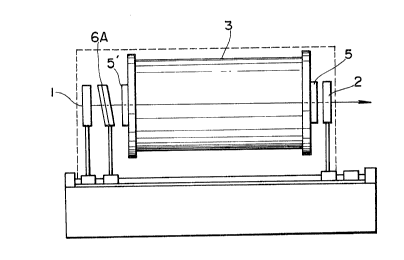
A preferred embodiment of this invention shown in Fig. 1 is
constituted by an excimer laser device comprising a total
reflection mirror 1 actlng as a rear mirror, an output mirror 2
acting as a front mirror and a chamber 3, and an air gap etalon
6~ disposed between the total reflection mirror l and the chamber
3. The chamber 3 is filled with a gaseous mixture of argon Ar
and fluorine F, a gaseous mixture of krypton Kp and fluorine F.
Further, discharge electrodes, not shown for exciting these gases
are contained in the chamber 3. Wlndows 5 and 5' are provided
for the opposite ends of the chamber 3.
~ - 3 -
lZ~35~
In the excimer laser device, a laser oscillation is
produced between mirrors 1 and 2 wh~ch constitute a stable
resonator so that laser light ls emitted ~rom the output
mirror.
The lateral mode of the laser light produced by the
excimer laser device has an extremely high order. In
other words, the lateral mode is multiple modes which are
very important for preventing the interference fringes in
the spectrum at the time of the reduced projection.
In each of the other gas laser devices and an injec-
tion lock type excimer laser device shown in Fig. 11,
since their lateral mode is a single mode or a similar
mode, such laser devices are not suitable for use in the
reduced project~on.
Let US describe the air gap etalon 6A acting as wave-
length selecting means. Since the etalon 6A is disposed
between the total reflection mirror 1 and the chamber 3 an
extremely high wavelength selection effect can be obtained
as will be described later, When the etalon is disposed
at the position shown ln Fig. 1. The light generated in
chamber 3 impinges upon the total reflection mirror after
it has passed through the etalon 6A. The light reflected
by the mlrror 1 passes again th~ etalon 6A and i8 then
- amplified. In other words, the light is subiectea to the
~avelength selection operation of the etalon during it~ go
and return passes. For th~s reason, ln th~s embodlment,
laser llght having an extremely narrow spectrum light
I
- 4 -
12~4352
can be produced.
Where the etalon 6A ls disp~sed between the output
mirror 2 and the chamber 3, a st~ong wavelength selecting
functlon described above can not be expec~ed so that it
becomes impossible to reduce the spectrum line width.
~ 'ig. 2 shows a modified embodiment of thls lnvention
in which in addition to the etal~n 6A described above,
another etalon 6B is disposed on the outslde of the cavity
of the excimer laser device. With this modification, the
lo ~ser light produced by the laser device ~hown in Fig. 1
would pass through the additlonal etalon 6B.
Fig. 3 shows another modifica~ion of this invention
wherein ~ (m ~ 2) etalons 6A are arranged between the
total reflection mirror 1 and the chamber 3.
Fig. 4 ~hows another modi~ication in which m etalons
6A and m etalons 6B shown in Fi~. 2 are aisposed.
The spectrum line Width at the time of tlatural
osc~llatlon (osclllatlon without the etalon) of the
excimer laser device ranges:
lOOcm 1 to 120cm 1 at full width
50cm 1 to 70cm 1 at half width
so that the optimum free spectrum range FSR of the etalon
would be
50cm 1 < ~SR _ 120cm 1
'~ Where an air gap etalon is used as the etalon, ~here
is the follo~ing relation between the air gap spaclng d
and the free spectrum range FSR of the et~lon
_ 5 _ I
12~43~2
FSR = 21d . . . . . (1)
where n represents the refractive index of the air gap.
By ~electing n=l, a = ~
Consequently, the range of ~ir gap d necessary fox
obtaining the optimum free spectrum range can be expressed
by the following equation (2)
42~m < d _ lOO~m . . . . . (Z)
Since there is a relation
~J 1 T F . . . . . ( 3 )
between the finesse F and the l1ne width (half width) a~
of the spectrum, the range of finesse F of the etalon
necessary to reduce the spectrum line width ~a~ of the
laser light spectrum to be less then 2 cm 1 (an optimum
line width for reduced projection, we can obtain 25 < F <
60 by substituting
~a~ - 2cm 1 and 50cm 1 ~ FSR < 120cm 1 into
equation l3)
The finesse F of the alr gap etalon can be shown by
the following equation ~4) in which FF represents the
surface finesse in the air gaps of the etalon and FR
~epresents the finesse caused by reflection.
~ ~ total finesse Ft = (F~ ~ FR ) / . . . (4)
3~2
Consequently, it is suff.icient to set the finesse
caused by the sur~ace finesse and the finesse FR caused by
reflection such that the followlng relation is satisf~ed
2~ < ~F~ + F 2~ 1/2 < 6
Thus, ln the embodiment shown ln Fig. 1, the specl-
fication of the et~lon 6A necessary to obtain a line width
2 cm 1 ls as follows. I
lo 1, free spectrum range: 50cm < FSR ~ 120cm 1 1¦
(the air gap space d is set to be ~2~m c d_ lOOl~m.
2. ef~ect~ve dlameter: larger than 2 mm
3. total finesse: 25 g Ft ~ 60
(FF and FR are set to satisfy a relation
o ( F F~ ) ~.60 )
In the embodiment shown in Fig. 2, let us call the
etalon 6A disposed in the cavity of the excimer laser
device as an internal etalon and call the etalon 6B
disposed or the outslde of the cavity as an external
etalon~ the specification of the internal and external
etalon 6A and 6B necessary to obtain a spectruM line width
of 2 cm 1 ls as follows.
Internal etalon 6A
1. free spectrum range: 50cm 1 < FSR < 120cm 1
(when the air gap spaciny d is set to
42~m < d < lOO~m,)
129~3~2
2. effective diameter: laryer th~n 2 mm
3. total finesse: 5 ~ Ft ~ 60
(FF and FR are set to satisfy a ~elation
'= F R -- )
External etalon 6B
1. free spectrum range: lOcm 1 < Ft < 20cm
(when t~e air gap spacing d is set to be
208~m - 2500~m.)
2. effective dlameter: larger than 2 mm
3 the overall finesse FaQ = Fin.FoUt,
product of the total finesse Ft ~ Fin of the internal
etalon 6A and the total ~inesse Ft = FoUt of
etalon 6B ls ~et to satisfy the following relation
25 ~ Fl F ~ 60
( FF and FR are set to satisfy a relation
25 < (FF2 + FR2) 1/2-Fin < 60 )
In the embodiment shown in Fig. 3, the specificatlon
for m etalons is aq follows.
As shown in Fig. 6, where m air gap etalons 6 are
arranged in multi-stages, according to equation (l), the
free spectrum range ~CRl of the first etalon is expressed
by
FSRl = 1/2 ndl . . . . . (S)
wherea~ the spectrum range of the k-th etalon (k 5 2-m) ls
-- 8 --
~ . .
3~i:
shown by
FSRl~ = l/(Fl-F2'~'Fk~ 2 n 1
where Fl and Fk represent the finesses of the first and
k-th etalons. To obtain the spectrum line width of 2
cm 1, the fr~e spectrum range FSRl shown ~n equation (5)
may be in a range of 50cm 1 _ 120cm 1 when n-l. Further-
more, equation (6) shows that the k-th free spectrum range
may satlsfy a relation
50cm~l ~ FSRk ~ F2 Fm) _
The overall finesse of respective etalons is ex-
pressed by
FaQ = Fl~F2 Fm . . . . . (8)
ln other words, in order to obtain a spectrum line
wldth of 2 cm 1, the overall finesse Fa may be in a range
of 25-60.
Accordingly, the speclfication for the m etalons 6A
of the embodiment shown in Fig. 3 is a~ follows.
1, The free spectrum range of the first etalon is
6Qt to satisfy a relation 50 < FSRl c 120, while that of
the k-th etalon is set to satisfy equation (8~
(in other words, the air gap spacing of the flrst etalon
~is set to satisfy a relation 42 ~ dl c 100 and that of the
k-th etalon is set to satisfy a ~elation 42 < dk / Fl F2 -
Fk_l) C 100)
12~4352
2. The effective diameter of ea~h etalon
larger than 2 mm
3. The overall f~nesse - FaQ is set to satisfy a
relation
~5 _ Fl'F2' ~ 'Fm < 60
Although in this embodiment~ the first to m-th
etalons are arranged in the order of incident of oscil-
lation light, This is only the purpose of the descrip-
tion, and it is clear that othex orders o arrangement can
be used. Thus so long as each etalon satisfies the above
described specification, the order of arrangement may be
random.
The following ~able I shows examples 1 - 12 of the
specifications of respective air gap etalons 6A and 68.
The specifications for the m internal etalons and m
external etalons of the embodiment shown in Fig. 4 are the
same as the specification for the m external etalons 6A of
the embodiment shown in Fig. 3. In this embodiment too,
the order of arrangement of the internal etalons may be
random so long as thc specificatlon described above is
fulfilled.
-- 10 --
I
1~43~:~
Table I
~xample of Air ~eflec~ Surface ~ffec- Total Free
Speciica- Gap tion Fineness tive Finesse Spectrum
tion Index Dla- l~ange
meter
l~m] [%] [6328nm] tmm] ~ ~t [cm-l]
, _., ,. ._ _
1 lO0 60 ~ l 50 3~ 5.2 50
2 100 70 A / 30 ~0~ 4.9 5
... .. ...
3 100 80 ~ / 30 30~ 5,44 50
. I
~ 100 90 ~ / 30 30~ 5-77 50
100 so ~ / 50 30~ 9.3 so
6 100 95 A / 30 30~ 5.~6 50
.. .... . . _ . . .. . . .. .
7 42 90 ~ / 50 30~ 9.3 120
8 38S 73 A / 50 30~ 7.0 13
_ _ _ _ _
9 500 ~0 ~ / 30 30~ 5.44 10
.... . . . .. _ . . . .
lo 500 62 ~ ~ 50 30~ 5.5 10
. . . ~
11 625 ~ 60 A / 30 30~ 4.23 8.0
12 926 50 ~ / 20 30~ 3 5,4
In this Table the surface ~inesse is represented by
uslng the oscillation wavélength ~ ~ 632.8 nm of a He - Ne
laser device.
The following Table II ~hows the lasex light spectrum
line wldth and the output ratio in cases ~here tlle inter-
nal etalon 6A and the external etalon 6B ~hown ln Fig. 2
and satlsfying the examples o the specifications shown in
~able ~ are suitably combined.
In Table II, the output ratlo means the ratlo of the
oscillation output when etalon~ 6A and 6B are not used to
~2~4352
that when the etalons are used.
Table II
Example of Speclflcation Specification L~ne Outp~t
Combination of Internal of External ~idth Ratio
Etalon Etalon ~cm 1] 1 % ]
1 1 2 1.5 30
2 1 10 1.1 16
_ .
. 3 2 9 1.2 12
4 2 10 1.1 14
3 9 1.0 14
6 3 10 1.3 11
I
7 4 _ 1.5 50
8 4 11 1.1 20
9 5 11 0.8 18
_ ~
6 10 oscillate
~ .
11 7 8 1.8 10
In example 10 of Table II, since the reflective
index of the internal etalon 6A is about 95%, the
throughput becomes small thus disenabling osclllation, but
in other examples, a line width of less than 2 cm 1 can be
obtained. The interference was investigated by passing
the laser lights o~ respective combinations through a pin-
hole and ~ound that no interference fringe was formed.
Thus it was found that the lateral mode of the laser llght
li~ of the multimodes that is there are sufficiently large
number of lateral modes.
- 12 _
~ .
.
352
The term "throughput" means the ratio of strength of
the inpu~ light when light of a selected wavelength is
passed through an etalon to the s~rength of the outpUt
light ls defined by the ~ollowing equation
~ 2
t = (1- )
where A s absorption index
R: ~eflective index
The following Table III show~ the result of experi-
ment~ where the number of internal etalons of the embodi-
ment shown in Fig. 3 was made to be m=2, and the specifi-
cations of the one and other internal etalons were suit-
ably selected and combined from Table I.
Table III
Example of Speciflcation Specification Line Output
Comblnation of Internal of External Width Ratio
EtalonEtalon [Cm-1] [ ~ 1
1 1 9 0.8 38
2 1 10 0.9 47
3 2 9 0.9 30
4 2 10 0.9 28
3 9 0.8 23
.
6 3 10 0.9 24
.
7 4 9 1,0 14
8 4 11 1.0 18
~9 5 11 0.7 14
_
7 a l.o 13
~ - 13 -
lZ94352
As shown in Table III ~n each of the combinations 1
10 a line width of less than 2 c~ 1 was obtained. Compar-
ison of these experimental data with those shown in Table
Il clearly shows that the
. 5 constru~tion shown in Fig. 3 has smaller power loss than
that shown in Flg. ~. Furthermore, a sufflc~ent number of
lateral mode~ was obtained with the combinations shown in
Table III.
The following Table IV shows the resl~lt of experiment
10 where only two external etalons were used as shown in Fig,
5.
Table IV
~ Example of Specif~ation speci~ation ~ine Output
! Combination of ~nternal of External ~idth Ratio
EtalonEtalon ~cm 1] [ ~ ]
I 1 1 9 1.8 3
r 2 1 10 1.9 2
3 ~ 9 1.9 2
4 2 lo 2 3
3 9 l.a 2
,
6 3 1 0 1 . 8 2
7 4 9 1.9 2
8 4 11 1.9 2
9 5 11 1.8 2
o 6 lo 1 . 9
1 7 8 1 . 8
31 29~35~:
As shown in Table IV, in each one of the combinations
1-11, a line width of less than Z cm 1 was ob~ained, but
I the output ratio was decreased slightly (1-3%) than the
¦ experimental data shown in Table II. This sho~s that when
¦ 5 only the external etalon 6B is used for decreasing the
¦ spectrum line width the power loss becomes large thus
I preventing practical use.
¦ Although in each embodiment shown in Figs 1-4, an
¦ air gap etalon was used as the etalon 6A, a solid etalon
I 10 can be substituted for the air gap etalon. However, it is
¦ necessary to use a solid etalon of the same specification
as the air gap etalon.
In the embodiments described above, the effective
diameter of windows 5 and 5' was set to be larger than 2
mm and a slit (aperture) of less than 2 mm was not instal-
led in the cavity of the excimer laser device.
Fig, 7 dia~rammatically sho~s a reduced projectio~
exposure device wherein light projected from a reduced
projection iight source 30 ls co~veyed to a wafer 36
through an integrator 31, a reflecting mirror 32, a
conden~er lens 33, a reticle 34 and a reduced projection
lens 35 so as to project a pattern on the rectile 34 upon
the wafer 36.
In thls apparatu9, where a high pr~sure mercury
lamp, for example, is used as the light source, it is
impo~sible to expo6e a fine pattern because thc maxlmum
resolution ~s only about 5.0 ~m. Furthermore, as the
- 15 -
~L2~4~S2
spectrum line width of the mercu~y lamp is relatively
wide, a color aberration compensation is necessary. For
this reason, it is necessary to ~se a reduced projection
lens 35 of a complicated construction comprising a com-
bination of glasses havlng d~fferent refr~ctlve lndices.ThiS not only makes difficult to design lens 35 but also
increases lts manufacturing cost.
Where the light source described above is used in the
embodiments shown in Figs. 1-4 laser light having spectrum
line widih of less than 2 cm 1 can be o~tained so that no
color aberration compensation is necessary. Accordingly,
it is possible to fa~ricate the projection lens with
quartz above, whereby the lens can be deslgned readily and
manufactured a~ a low cost.
With this embodiment, as it i3 possible to decrease
the spectrum line wldth without decreasing the number of
the lateral modes there is no fear of producing such
problem as speckle at the time of projection.
Accordingly, it is possible to construct projection
apparatus of high resolution.
In an excimer laser device, since the reflective
lndex of the output mirror has an influence upon the
output efficiency thereof, the laser outp~t ~ould decrease
unless the reflective index is optimum.
~ Let us consider how to opti~ize the reflective index
of the output mirror in order to efficiently deriving out
the laser output of the excimcr laser device.
- 16 -
~2~435Z
In the embodiment shown in Fig. 1, an air gap etalon
having a free spectrum range of 42 cm 1, a finesse of 1.7,
and an effective diameter of 30 mm was used and an
I experiment Was carried out for investi~ating ~he relation
between the reflective index of the output mirror 2 and an
excimer laser device utilizing Kr ~nd F.
Fig. 8 ~hows the resul~ of this experiment ~howing
that a maximum output ~180 mJ) can be taken out when the
output mirror 2 has a reflective index of about 8~.
10 Taking one hal~ value t90 mJ) of the maximum output as a
threshold value Tl, for judging high o~ low of the effi-
¦ ciency of the excimer laser device, as can be noted from
Fig. 8, a sufficiently practical output can be efficient~y
taken ou~ when the reflective index of the oUtput mirror
lies ln a range between 2~ and 43~.
As the reflective index of the output mirror isincreased, the number of turns of light in the cavity
~, lncreases 60 that the spectrum llne width of the laser
light becomes narrow. Fig. 9 is a graph showing the
reflective index of the output mirror 2 and the spectrum
llne width.
Fig. 10 shows a graph obtained by dividlng the laser
output showing ~ig. 8 with the spectrum llne width shown
in Fig. 9, the qraph showin~ the relation between the
~reflective index of the output mirror 2 and the laser
device output per un~t spectrunl llne width.
Fig. 10 ~hows that the laser output per unit line
- 17 -
1~9~352
wiath becomes a maximum (8.6 mJ/cm 1~ whe~ the reflective
index o~ the o~tput mirror is about 20%. Taking one half
value ~4.3 mJ/cm 1) of the maximum laser output per unit
line width as a threshold value T2 for ju~ging high or low
of the efficiency of the laser output per unit line width,
it is possible to efficiently take out the laser output
per unit line width when the reflective index of the
output mirror lies i~ a range of from 1~ to 49~, as can be
noted from the graph.
Tt should be understood that the relation shown in
Fig. 1~ also holds true for the embodiments shown in Figs
1-4,
Brlefly stated, in the above described embodiments
employing internal etalon 6A, 80 long as the re~lective )
~ndex of the output mlrror 2 is set in a range of from 1
to 49~, it ls possible to obtain sufficient laser output
per unit spect~um llne wi~th.
- lB -