Note: Descriptions are shown in the official language in which they were submitted.
3~3
The invention relates to a method and an apparatus for
compliance and posltion control of a teleoperated rohotic system.
This application discloses the use of Myoelectric signals to
control compLiance o~ a robotic system.
Teleoperate~ robotic systems may b~ used to handle toxic
material, manoeuvres in space, un~erwater searches or tactical
military manoeuvers. For example a teleoperated robot arm may be
used to hold a tool in a radiation filled environment since a
human subject would be exposed to the danger of working in such an
environment. Thus the teleoperator must be able to control the
position and compliance of the robot arm from a remote location.
It is known in present day technology that actuators are
used to control the joints in a robotic system. Hydraulic or
pneumatic cylinders, or electrical motors constitute the standard
actuating technology used in the current generation of robotic
systems. Known robotic systems using these types of actuators are
basically non-compliant. Two principal techniques have been used
to alleviate this deficiency. Compliance can be built into a
robotic system by permittiny spring-like bending of some elements
in the system. However, springs are passive components, and they
oscillate when excited, adding to the difficulty of controlling
the position of a robotic arm. One approach would be to
dynamically vary the control in anticipation of the oscillations
o~ the spring. Another approach is to generate an active
"pseudo-compliance" in the control software of the robo~ic system.
Proximity sensing and a feedback control loop are needed to
achieve the "co~pliant" behaviour from actuators which are
themselves noncompliant. However, compliance capabilities
lZ~3~33
achieved with these techniques are limited. They do not enable an
arm to accommodate impulse loads nor touch a work surface with
varying pressures and attitudes.
It iS the purpose of this invention to provide an
independent co~pliance control in each degree of freedom of the
robotic system. ThiS independent compliance control capability
allows dexterous assembly operations to be done without elaborate
fixture of a workpiece.
A method of controlling compliance and position of an
actuator in each degree of freedom of a teleoperated robotic
system is disclosed. The method comprises the steps of acquiring
a raw myoelectric signal from the muscles of a teleoperator:
processing the raw myoelectric signal into a compliance control
signal; and applying the control siynal to an actuator. Although
any type of actuator will function satisfactorily it is
preferable to use an actuator having characteristics that are
analagous to human muscle characteristics. An actuator which has
human muscle like characteristics is disclosed in U.S. Patent
4,733,603.
A brief description of the attached drawings will aid in
understanding the preferred embodiment of the invention. In the
drawings:
Figure 1 is a block diagram illustrating an embodiment
of the invention.
Figure 2 shows an example of force versus displacement
link family of curves for an antagostic pair of
actuators.
393
Figure 3 illustrates in detail a preferred means for
procesSing the myoelectric signals.
Figure 4 illustrates one embodiment of the invention.
Figure 5 illustrates a schematic diagram of the
embodiment o~ the in~ention illustrated in
Figure 4.
A myoelectric signal is derived from the depolarization
of contracting individual muscle fibres. Each muscle fibre is
surrounded by a membrane semipermeable to certain ions. In the
resting condition, the intracellular region is electrically
negative with respect to the extracellular fluid. When
stimulated, the fibre becomes permeable to ions which rapidly move
into the interior, causing potential reversal across the fibre or
itS "depolarization". ThiS iS followed by a "repolarization"
whereby the re~ting potential condition is restored. The process
Of depolarization and repolarization iS as~ociated With a
momentary mechanical contract~on of the muscle fibres. It can be
repeated but only after a certain resting period.
One nerve fibre controls an assembly of muscle fibres,
and together they constitute a motor unit. Muscle fibres of one
motor unit are activated almost simultaneously, giving rise to a
complex electrical potential transient in the nearby extracellular
fluid. A musc]e encompaSses numerous motor units acting
asynchronously. A myoelectric signal measured on the skin surface
reflects the cumulative effect of all muscle-fibre action
potentials in the proximity of the electrodes. The observed
electrical signal is strongly related to the muscle contraction
and, consequently, to the number of motor units and their rate of
activation. Most of the energy of the resulting waveform lies in
12~393
a frequency range between 30 and 200 Hz and the peak-to-peak
amplitude may range up to several milivolts, when measured with
electrodes on the skin. An instantaneous amplitude of the signal
iS not useful for eontrol pUrpoSeS. Elowever, "raW" signals can be
averaged and processed to represent the "amount" of the
myoelectric signal that is subject to conscious voluntary
eontrol.
Referring now to figure 1 which shows a block diagram of
the invention, myoeleetrie signals are aequired from a
teleoperator 1, by a means 10 for aequiring said myoelectric
signal. Electrodes may be used to aequire the myoelectrie signal.
This signal is then processed by a processing means 20 and the
output from the processing means 2~ is used to control fluid flow
in mean9 30 to the aetuator 40. The aetUator 40 supplies a foree
signal to the system depending upon the amount of fluid received
from the actuator.
As shown in Figure 2, the position of the arm ean be
eontrolled by the ratio o~ pressures acting upon a pair of
antagonistie aetuatorS. In thiS embodiment of the invention a
pair of actuators is supplied with position and compliance control
signals. For example, a right displaeement of 5 mm is obtained
with 25 psi pressure in the right actuator and 10 psi in the left
aetuator. The same displaeement ean be aehieved with other
eombinations of pressures in the two actuators, (as demonstrated
by interseetion of the vertieal line with other pressure eurves in
Figure 2). When pressures in both actuators are increased while
maintaining a eonstant pressure ratio, the angular position of the
arm is maintained, but its stiffness inereases, i.e., its
3~33
compliance decreases. Consequently, compliance o~ actuator
proportional control system can be dynamically varied according to
the absolute actuator pressures, independentl~ of the joint
angle.
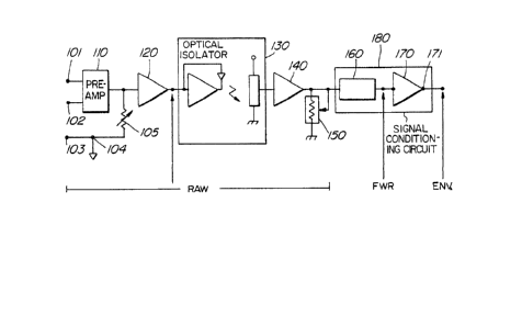
One possible processing means used to process the
myoelectric signal acquired ~rom the teleoperator is illustrated
in Figure 3. Myoelectric signals are picked up by a pair of
electrodes 101 and 102. A reference electrode 103 is connected to
an isolated ground at point 104. The outputs of the two
electrodes 101 and 102 are input into a preamplifier stage 110.
The signal from the reference electrode 103 is fed through an
amplification control means 105. The output of the
preamplification stage 100 and the output from the amplification
control means 105 is input into a buffer preamplifier 120. The
output of the buffer preamplifier 120 is input into an optical
isolation circuit 130 as shown in Figure 3. The purpose of the
optical isolation circuit 130 is to prevent the teleoperator from
receiving a shock from the processing means 100. The output from
the optical isolation circuit 130 is input into an ampllfier
buffer 140 the output of which is input into an attenuation
control means 150. The output from the attenuation eorltrol means
lSO is input into a signal conditioning circuit means 180 for
rectifying, integrating and averaging the signal. The resulting
output signal is the envelope of the myoelectric signal input from
electrodes 101 and 102. As illustrated in Figure 1 the output
signal from the myoelectric processor is supplied to the means 30
for controlling the liquid flowing to the actuator 40.
One embodiment of the invention is illustrated in
3~3
Figure 4. One single joint 201 is controlled by two actuators 210
and 220. Although the single joint 201 is shown to be controlled
by two actuators, any number of actuators may be used to control
the single joint. The total number of actuators in a robotic
system will be a function of the number of joints in a robotic
system.
A computer controller 250 receives an input from
processing means 251 for processing myoelectric signals from the
teleoperator and an input from pressure transducers 212 and 222.
The actual pressure measured in the actuators 210 and 220 by the
transducer 212 and 222 and the signal received from processing
means 251 are compared by the computer controller 250. The
outputs of the computer controller 250 are supplie~ -to the
servovalves 230 and 240. The output from the computer controller
is a control signal which i5 a pressure error signal multiplied by
a proportional gain. The compUter controller 250 Can be for
example, a l~-bit 32020 coprocessor although any general purpose
microprocessor will work.
The servovalves 230 and 240 control the amoUnt of flUid
that is passed through to the actuators 210 and 220. If the
actUators 210 and 220 are operated by air f low then the
servovalves 230 and 240 are pneumatic and if the actuators 210 and
220 are operated by flow of liquid then the servovalves 230 and
240 are hydraulic. The amount of fluid (gas/liquid) delivered to
the actuators 210 and 220 controls the amount of force output from
the actuators. As illustrated in Figure 2 the position and
compliance of a robotic system is controlled by the amount of
lZ~ 3~33
fluid pressure in the actuator.
Figure 5 is a block diagram illustrating the signal flow
oi the embodiment of the invention as illustrated in Figure 4.
The use of myoelectric signals for controlling the
position and compliance of an aCtUator offers particularly
significant advantages in telerobotic operations. The
teleoperation of compliance, by means of myoelectric signals
provides a dynamic and intuitive control of joint stif fness by
human operator, thus permitting a teleoperated robot to undertake
impulse dominated tasks in unstructured environments.
Although the invention has been illustrated in terms of
a specific embodiment other processing means, means for acquiring
the myoelectric signals, and meanS for providing the actuators
with liquid flow may be used without departing from the spirit and
scope of the invention.