Note: Descriptions are shown in the official language in which they were submitted.
5~i
DUST COLLECTOR
BACKGROUND ~F THE INVENTION
Field of the Invention
This invention relates in general to a dust collector
and, in more particular, to such a device of the type which
separates the dust particles from a vortex of air developed
in a drum.
Description of the Prior Art
There have been various types of cyclone dust
collectors developed in the prior art which, as might be
represented by Japanese laid-open utility model application
56-168054 proposed by the application of this invention,
typically comprises a dust chamber carrying at an upper part
thereof an exhaust pipe in which a funnel-shaped cyclone
drum is installed. The drum is formed to open at a lower
end thereof into the chamber. With this arrangement, when
negative pressure is developed in the chamber to introduce
dust carrying air into the chamber where it is caused to
swirl by the circular wall surface of the chamber. The
swirling air then makes its way into the drum through its
lower opening, thereby further accelerating its swirling
speed. Centrifugal force in the drum acts to separate the
dust particles contained in the air streams. Dust particles
thus centrifugalized are allowed to drop along the inside
slope of the funnel-shaped drum all way onto the bottom
where they deposit for subsequent disposal.
- 1 -
1~'34S~i
However, these conventional dust collectors have
been found to suffer from the disadvantage that the vortex
of air developed in the drum has tended to blow centrifugalized
dust particles about to drop along the inclined inside surface
of the drum, often resulting in poor performance of dust col-
lection. One proposed solution is to steepen the inside slope
of the funnel-shaped drum to such an extent that the dust
particles, upon centrifugalization, are allowed to take a
quick fall before they are carried away in the vortex of
the air. But this change in the design of the drum would
give rise to a problem of increasing the overall height of
the collector.
The present invention has been proposed to eliminate
the above-mentioned drawback of the conventional cyclone dust
collectors.
SUMMARY OF THE INVENTION
It is therefore a primary object of the present
invention to provide an improved cyclone dust collector
which is capable of efficiently separating the dust
particles from a vortex of air by centrifugalization.
It is another object of the present invention to
provide such a dust collector which is compact in construc-
tion.
The above and other objects, features and advantages
of the present invention are achieved by a cyclone dust
collector which comprises a cylindrical shell vertically
divided by a horizontal dividing plate into a pair of
-- 2
129'15~i6
.
upper and lower dust chambers. An air inlet is provided
mounted in the outside wall of the lower chamber to permit
the entrance of dust-containing ambient air into the shell.
Negative pressure generating means is provided in the shell
to create a negative pressure in the upper chamber through
a suction port provided in it. A communicating duct is
mounted substantially in the center of the dividing plate in
such a manner to extend downwardly into the lower chamber
to establish air-flow relationship between the chambers.
A cyclone drum with a closed bottom is mounted in the lower
chamber in such a manner to enclose the duct and spaced
away from the lower surface of the dividing plate to define
a narrow air gap between the plate and the top end of the
lower chamber. A disk is provided supported in the drum at
a height that divide the drum inside into a vertical pair of
upper and lower spaces and spaced away from the lower end of
the duct.
BRIEF DESCRIPTION OF THE DRAWINGS
Fig. 1 is a cross-section view of a first preferred
embodiment according to the present invention; and
Fig. 2 is a cross-section view of a second preferred
embodiment of the present invention.
DETAILED DESCRIPTION OF PREFERRED EMBODIMENTS
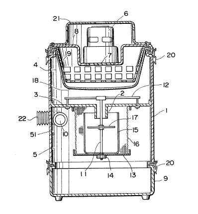
Referring first to Fig. 1, which shows a first
preferred embodiment of the dust collector according to the
present invention which comprises a cylindrical shell 1,
which is divided vertically by a horizontal dividing plate
lZ~566
3 into a pair of upper and lower dust chambers 4 and S. The
shell 1 has its top opening tightly closed by a top lid 8,
which may preferably be detachably secured with suitable
fasteners 20 at locations along the periphery of the lid to
provide easy maintenance access to the inside of the shell 1.
On the lid 8 is centrally mounted a ventilating
fan 6, installed to have its front faced downward. Opposite
the front of the fan 6 is bored centrally in the lid 8 an
exhaust hole 7 to permit escape of the internal air from
within the shell 1 as when the fan 6 is operated. Pre-
ferably, the fan 6 may be protected by a cover 21 removably
secured over the shell 1.
Also, the bottom opening of the shell 1 is tightly
closed by a bottom lid 9, which may preferably be detachably
secured with fasteners 20 at locations along the periphery
of the lid for easy maintenance. Preferably, the bottom lid
9 may be shaped like a tray to receive the dust and dirt
collected by operation; whenever a deposit of dust
particles is formed on the tray 9, it will be removed and
transported in order to empty the deposit into a waste
bucker or disposer.
The shell 1 is equipped with an air inlet 10 in the
wall 51 of the lower chamber 5. Preferably, the inlet 10 may
be positioned at such an angle so as to hold its axis
tangential to the circular circumference of the wall 51.
This arrangement enables the air entering the lower chamber
5 through the inlet 10, when negative pressure is developed
-- 4
12~ ~566
inside the shell 1 by the fan 6 in operation, to flow along
the inside wall surface of the lower chamber 5 into a vortex.
A communicating duct 2 is centrally mounted in the
dividing plate 3 to extend downward into the lower chamber
5 establishing air-flow relationship between the chambers 4
and 5. Opposite the bottom opening of the duct 2 is dis-
posed centrally in the lower chamber 5 a cyclone drum 15
having a closed bottom. The drum 15 is mounted on a platform
13, which is supported by a hanging bolt 11. The bolt 11 is
secured at a top end thereof to a support base 12 that is
mounted in fixed position on the upper surface of the plate
3, and extends downward into the lower chamber 5 through
the duct 2 to removably secure the drum 15 to the platform
13.
A disk 17 is horizontally supported within the drum
15, properly spaced away from the dividing plate 3, dividing
the drum inside into a pair of upper and lower spaces.
The upper space is provided to enable the air entering the
drum 15 to develop, upon impinging on the disk 17, into a
high-speed vortex of air for centrifugalization of dust
particles contained therein. The lower space beneath the
disk 17 is provided to permit the dust particles separated
to fall onto the bottom lid 9 without being affected by the
swirling air occurring above the disk.
The platform 13 is set by a nut 14 fitted about the
bolt 11 to a predetermined height such that the drum 15
is properly spaced away from the lower surface of the plate
-- 5
1~4c5~i6
3 enough to define an air gap between the plate and the
upper end of the drum 15. This air gap is dimensioned to
enable the air swirling about the drum 15 to enter, by
suction developed by the fan 6, into the drum with accelerated
speed.
A wire filter 16 formed into a cylindrical shape
larger in diameter than the drum 15 is provided to enclose
the drum. The cylindrical filter 16 is provided to filter
out the larger dust particles from the swirling air as it
flows into the drum 15.
Opposite the exhaust hole 7 in the upper chamber
4 is supported a filter 18 for screening the finer dust
particles from the air driven, by suction from the fan 6,
from the upper chamber through the hole 7. Preferably, the
filter l8 is held against a rigid frame 19 having a per-
forated front surface enough to permit the ready passage
of air therethrough. The frame 19 is provided to keep the
filter 18 at a proper distance off the hole 7, so that
suction developed by the fan 6 will not cause the filter 18
to be sucked into the hole 7.
A flexible hose 22 may be connected to the inlet 10
for increased convenience of dust collecting operation.
Since the system of the present invention has so far
been expounded, operation will be briefly touched upon to
provide a better understanding of the invention.
When the fan 6 is energized, negative pressure
developed inside the shell 11 drives ambient dust-carrying
-- 6
45~;;6
air to enter the lower chamber 5 through the inlet 10 and
form a vortex. The swirling air then enters the drum 5,
leaving behind the larger dust particles caught up in the
cylindrical cloth 16, through the air gap beneath the plate
3 into a rapid vortex due to the venturi effect. Upon
impinging upon the disk 17 within the drum 15, the flowing
air further develops into a swirling flow of accelerated
rate and moves at a high speed through the duct 2 and then
the exhaust hole 7, while separating the dust particles by
centrifugalization. The centrifugalized dust and dirt are
allowed to drop along the inside wall surface of the drum 15
passing the disk 17 onto the bottom plate 9.
Fig. 2 shows another preferred embodiment of the
present invention, in which a cyclone drum 25 is directly
mounted in fixed position on the bottom lid 9. The drum 25
carries at an upper end thereof a wired cloth 26 formed
into a conical shape adapted for screening the larger dust
particles fro~ a swirling flow of air introduced through
the inlet 10.
In the upper chamber 4 is provided a flexible filter
28 that is loosely spread over a cylinder-shaped frame,
which is provided to keep the flexible filter 28 away from
the exhaust hole 7 so that, even when negative pressure
developed in the hole 7 by the fan 6 pulls the filter to
full upward swelling, it will not be sucked into the hole.
A weight 30 is sewn to the center of the filter 28 to give
momentum to the filter as it is swung back and struck against
566
a horizontally spread wired cloth 23 over the plate 3 to
shake off the dust particles that might remain adhered to
the backside of the filter, as when the fan 6 is de-energized
to remove the suction. A dust tray 24 is mounted just below
the cloth 23 to receive such loosened dust from the filter 28.
Although, in the above preferred embodiments, the
swirling air in the upper chamber 5 is made to flow into the
drum through the air gap defined between the plate 3 and the
upper end of the drum 15, in an alternate embodiment, a
hole or holes may be provided in the wall of the drum 15 to
permit the entrance of flowing inside air. Such holes may
preferably be formed to hold their axis at an angle tangential
to the circular circumference of the drum so that the air
entering the holes will flow along the inside wall of the
drum into a proper vortex.
It is to be understood that changes and modifications
are possible without departing from the spirit of the present
invention and that the scope of the invention should be
limited, not by the above descriptions and drawings given
merely by way of illustration, but by the appended claims
which follows.