Note: Descriptions are shown in the official language in which they were submitted.
~ f~ 7~7
WIND SHEA~ DETECTION SYSTEM
BACRGROUND OP THE INVENTION
Field of the Invention
This invention relates generally to wind
shear detection systems, and more particularly to
airborne wind shear detection systems for alerting
the pilot of a wind shear condition if the aircraft
penetrates a wind shear condition of sufficient force
to pose a hazard to the aircraft.
Descri~lon of the Prior Art
Various wind shear detection systems are
known. Among these include ground based systems such
as systems that utilize a plurality of wind speed and
direction measuring stations placed about an airport
in conjunction with a system for analyzing the magni-
tude and direction of the wind at the various stations
to provide an indication of a wind shear condition.
Other ground based systems utilize Doppler radar lo-
cated at airports.
Airborne systems are also known~ Amon~
such systems are systems that compare airmass derived
parameters such as airspeed with ground speed derived
.;i,~. ~.
707
--2--
from a radar system. In the event of a rapid change
in airspeed relative to ground speed, a wind shear
condition is indicated. Other systems compare airmass
derived signals with inertially derived signals to
generate a signal representative of wind shear when
the rate of change of inertially derived parameters
varies from the rate of change of airma_ derive para-
meters by a predetermined amount. Two such systems
are disclosed in United States Patent Nos. 4,012,713
and 4,079,905. ~oth of these patents disclose systems
that compare a longitudinal accelerometer signal that
has been corrected for the effect of gravity with an
airspeed rate signal and provide a wind shear signal
when the difference between the accelerometer derived
~5 acceleration signals and the airmass derived rate
signals exceeds a predetermined amount. The '905
patent also takes into account a downdraft drift angle
that is a function of vertical acceleration and air-
speed rate. Still other systems monitor the rate of
change of deviation from a glide slope beam or an ILS
beam to provide a signal representative of wind shear.
The system disclosed in the applicant's Canadian Patent
Application Serial No. 529,103, filed February 5, 1987
compares a rate of change of airspeed signal with a
composite signal derived from inertially derived and airmass
derived signals and does not require the inertial gravity
correction utilized by the systems contemplated by the
U.S. Patents 4,012,713 and 4,079,905.
While all of these systems provide some
39 indication of wind shear, the ground based systems
are responsive only to conditions in the vicinity
where the transducers are placed, and are not respon-
sive to dangerous types of wind shear such as micro-
bursts which form and dissipate rapidly.
While airborne wind shear protection systems
are more responsive to conditions in the vicinity of
the aircraft than are ground based systems, many of
~;
~ J~7
,, ~
--3--
them require Doppler radar or signals such as inertial
navigation signals, glide slope signals and other
signals that are not available on older aircraft.
Also, the airspeed rate signals utilized by the air-
borne systems tend to be noisy because they are ob-
tained by differentiating an airspeed signal. The
nature of the differentiation process is to emphasize
rapid changes in the signal applied to the differen-
tiator. Consequently, short term components of the
airspeed signal that are not: related to wind shear
produce large peaks in the airspeed rate signal. Such
peaks must be limited, filtered or otherwise processed
to avoid nuisance warnings. In addition, the prior
art systems calculate wind shear along the longitudinal
and normal axes of the aircraft or along the horizontal
and vertical coordinates of the earth. This can result
in errors during high bank angle turns and other
dynamic maneuvers.
S~MMARY OF THE INVENTION
Thus, it is an object of the present inven-
tion to provide a wind shear detection system that
overcomes many of the disadvantages of the prior art
systems.
It is yet another object of the present
invention to provide a wind shear detection system
that utilizes signals that are present in most air-
craft.
- It is yet another object of the present
invention to provide a wind shear detection system
that does not require the use of an airspeed rate
signal.
It is yet another object of the present
invention to provide a wind shear detection system
that maintains its accuracy under e~treme flight con-
ditions such as high bank angle turns and other dynamic
maneuvers.
~2~ 7
--4--
It is yet another object of the present
invention to calculate wind shear along the velocity
vector of the aircraft.
Thus, in accordance with a preferred embodi-
S ment of the invention, there is provided a wind sheardetection system that requires only normal and longi-
tudinal accelerometer signals, an angle of attack
vane signal, a vertical speed signal and an airspeed
signal from the aircraft. These signals are employed
in a shear equation that utilizes longitudinal ac~
celeration, normal acceleration, angle o~ attack,
flight path angle and airspeed to generate a number
that is a function of the aforesaid variables and
provides an indication of wind shear. In addition,
the wind shear may be compensated for the effects of
roll and sideslip~ Also, by making the wind shear
calculations along the velocity vector of the aircraft
rather than along the other coordinates, errors due
to extreme maneuvers are minimized.
DESCRIPTION OF THE DRAWING
These and other objects and advantages of
the present invention will become readily apparent
upon consideration of the foll~wing detailed descrip-
tion and attached drawing, wherein:
FIG. 1 is a vector diagram illustrating the
relationship between various parameters used in detect-
ing a wind shear condition;
FIG. 2 is a block diagram illustrating the
basic principles of operation of the system according
to the invention;
FIG. 3 is a vector diagram illustrating the
relationship between various parameters utilized in
detecting a wind shear condition along the velocity
vector of an aircraft; and
FIG. 4 is a block diagram illustrating logic
circuitry that is responsive to a wind shear condition
along the velocity vector of the aircraft.
7~7
--5--
DETAILED DESCRIPTION
In the description of the present inven-
tion, various accelerations such as longitudinal ac-
celeration, normal acceleration and various angles
such as pitch angle, flight path angle, etc., will be
discussed, and these angles and accelerations are
illustrated in FIG. 1. Throughout the discussion
herein, it should be understood that the term "inertial
acceleration signal" can refer to related signals
other than pure inertial acceleration signals, such
as an inertially derived siqnal, derived from both
inertial and non-inertial transducers.
Referring to FIG. 1, there is shown a pair
of horizontal and vertical coordinates designated by
the reference numerals 10 and 12, respectively. A
representation of an aircraft 14 is also shown in
FIG. 1, and a pair of vectors 16 and 18 represent the
longitudinal and normal axes of the body of the air-
craft, with the vector 16 passing through the longi-
tudinal center line of the aircraft and the vector 18
being perpendicular to the vector 16. A dashed line
20 represents the flight path of the aircraft, and in
the illustration of FIG. 1 represents a descending
flight path.
The angle between the horizontal axis 12
and the longitudinal axis 16 of the aircraft is defined
as the pitch angle and represented by the symbol e.
The angle between the flight path 20 and the horizontal
reference 12 is defined as the flight path angle and
is represented by the symbol Y. The angle between
the longitudinal axis of the aircraft 16 and the flight
path 20 is known as the angle of attack of the aircraft
and is represented by the symbol Y. The flight path
angle y is negative for a descent and positive for
ascent. Thus, the angle of attack Y is equal the
flight path angle y plus the pitch angle ~.
--6--
In addition, various accelerations and ac-
celerometer signals will be discussed. One such signal
is a longitudinal accelerometer signal, AL, which is
the signal obtained from an accelerometer mounted
parallel to the longitudinal axis 16 of the aircraft.
The signal from the longitudinal accelerometer is a
function of the longitudinal acceleration of the air-
craft, and because of the influence of gravity, the
pitch angle e. Another such signal is the normal
accelerometer signal, AN, which is the signal obtained
from an accelerometer positioned parallel to the normal
axis 18 of the aircraft. The normal accelerometer
signal is a function of acceleration along the normal
axis of the aircraft as well as gravity, pitch angle
S e and roll angle 0. The roll angle 0 is the angular
derivation from horizontal about the longitudinal
roll axis of the aircraft. Horizontal acceleration,
AH, is a signal representative of acceleration along
the horizontal axis 12. An accelerometer mounted
parallel to the horizontal axis 12 would provide the
horizontal acceleration signal, AH. Finally, a ver-
tical acceleration signal, Av, is a signal representa-
tive of acceleration along the vertical axis 10. An
accelerometer mounted parallel to the vertical axis V
would provide a signal representative of the sum of
any vertical acceleration and the effects of gravity,
g, or 32.2 feet/second. A vertical gyro would provide
signals representative of the pitch angle e and the
roll angle ~.
Recapitulating the above, the various ac-
celerations and angles to be considered are as follows:
AN = normal accelerometer signal;
AL = longitudinal accelerometer signal;
AH = horizontal acceleration;
AV = vertical acceleration;
g = gravitational constant = 32.2
feet/second;
--7--
= angle of attack (AOA);
~ = pitch angle;
0 = roll angle;
y = flight path angle.
S In determining some of the above parameters,
other parameters may be required. These include:
h = vertical speed (which may be obtained
as a Z-velocity signal from an inertial
navigation system or a barometric altitude
rate signal; and
v = airspeed (which may be a true airspeed
signal VT)-
In the system according to the present inven-
tion, a wind shear representative signal is obtained
by computing a composite signal based on inertially
derived accelerations, angle of attack, flight path
angle and vertical velocity, and comparing the computed
signal with an airmass derived velocity signal such
as true airspeed. The difference between the composite
signal and the airmass derived velocity will be a
measure of wind shear.
Because the present system does not employ
a vertical gyro, and only normal and longitudinal
accelerometer signals AN and AL, are employed, the
~5 horizontal acceleration, AH, must be computed. The
computation is as follows:
(1~ AL = AH cos ~ ~ (g + Av) sin e
(2) AN = (g ~ Av) cos e - AH sin e
Substituting the quantity (g + Av) from
equation (2) into equation (1), we obtain:
( 3 ) AL = AH + AN tan e
cOs e
From equation (3) above, the horizontal
acceleration, AH, can be calculated if the pitch angle
e is known. However, to obtain the pitch angle direct-
ly, a vertical gyroscope is required. To avoid the
need for a vertical gyroscope signal, the no-wind
.707
--8--
condition of the pitch angle being equal to the angle
of attack plus flight path angle is utilized as
follows:
(4) ~ = ~ + Y
Utilizing this condition, the need for a
vertical gyroscope is avoided and the system also
becomes sensitive to vertical winds and up and down
drafts because angle of attack and flight path angle
do not add up to pitch in the presence of vertical
wind.
Making small angle approximations that for
small angles cos 9 = l and tan e = e in radians, equa-
tion ~3) becomes:
(5) AL = AH + AN (~)
lS Rearranging terms to solve for horizontal
acceleration, we obtain:
(6) AH ~ AL ~ AN (~)
Utilizing the no-wind condition approximation
for e, equation (6) becomes:
(7) AH = AL ~ AN ( ~+ Y~
The AH signal is an acceleration signal
which could be compared with an airmass derived air-
speed rate signal to provide a shear signal, as is
done in the above referenced Canadian Patent Application
Serial No. 529,103, filed February 5, 1987. However, to avoid
utilizing an airspeed rate signal, the AH signal is
combined with an airmass derived velocity signal, v,
which may be true airspeed, and integrated to provide
a composite velocity signal derived from both airmass
and inertially derived parameters. The composite
velocity signal is then compared with an airmass de-
rived airspeed signal (e.g., true airspeed) with the
difference being representative of wind shear. Mathe-
matically:
,, ,ii~
.. ~, . ....... -
dt,~ r~7
- 9 -
(8) shear = AL ~ AN (~ + Y) + v
l ~ Ts
where s is the LaPlace operator and T is the ~ntegra-
tion time constant.
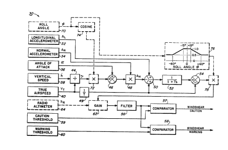
S A circuit for solving the shear equation
(8) above is illustrated in FIG. 2, and generally
designated by the reference numeral 30. Although the
circuit is illustrated as a series of functional blocks
for purposes of clarity, it should be understood that
the system need not be implemented exactly as shown
and that various analog and digital implementations
are possible. The system 30 utilizes various inputs
such as a signal from a longitudinal accelerometer 32
mounted parallel to the longitudinal axis of the air-
craft, a normal accelerometer 34 mounted perpendicular
to the longitudinal accelerometer 30 and an angle of
attack vane 36, which may be, for example, a vane
extending laterally from the side of the aircraft
that orients itself parallel to the local air flow
past the vane. The angle of attack vane signal is
combined with other parameters, such as, flap position
signals as well as a constant peculiar to a parti-
cular aircraft to provide the angle of attack signal.
In addition, a vertical speed signal source 38 provides
a signal, h, representative of the vertical speed of
the aircraft. Such a vertical speed signal may be
obtained by differentiating a barometric altitude
signal. An airspeed signal source 40 such as an air-
speed transducer whose output has been compensated
for environmental variations provide a signal represen-
tative of true airspeed, VT, is also provided. Al-
though two separate instruments are shown, the baro-
metric altitude and airspeed data can be obtained
from an air data computer, and the vertical velocity
may be obtained from the Z-velocity output of an iner-
tial navigation system. Also various airspeed signal
sources may be employed, and consequently, a
--10--
generalized term v, is employed in the following equa-
tions; however, vT may be substituted to v.
Because the flight path angle Y cannot be
obtained directly from any of the aforementioned trans-
ducers, the flight path angle y must be computed asfollows:
(9) y = arcsin (h/v)
which for small angles becomes:
(lO) y = h/v, where y is in Radians.
Thus, by dividing the barometric rate signal,
h, by the airspeed signal, v, for example, by means
of a divider circuit 44 (FIG. 2), a signal representa-
tive of the flight path angle y is obtained. During
the initial portions of this discussion, the components
shown by dashed lines will not be considered because
they relate to optional features of the basic system.
The flight path angle signal thus obtained is added
to the body angle of attack signal derived from the
angle of attack vane 36 by a summing junction 46 to
provide a signal representative of the sum of the
angle of attack and flight path angle signals (~ + Y).
The vertical speed signal used for the computation of
the flight path angle (y), essentially indicates iner-
tial vertical speed, i.e., the actual vertical motion
of the aircraft. Thus the resulting shear equation
will also respond to vertical shears (e.g., up or
down drafts) because the derived angle of attack (~)
and the inertially derived flight path angle (y) do
not add up to the pitch angle (e) in the presence of
up or down drafts. The output of the summing junction
46 is multiplied by the normal accelerometer signal
in a multiplication circuit 48 to provide the AN(~ + ~)
term. The airspeed signal from the airspeed transducer
40 is added to the longitudinal accelerometer signal
by a summing junction 50 which also subtracts the
AN~+ Y) term from the sum of the airspeed and longi-
tudinal accelerometer signals. The output of the
~2~
--11--
summing junction S0 is filtered by an integrating
filter 52 having a time constant, T, equal to, for
example, one second. The output of the integrating
filter 52 is compared with the true airspeed signal
S by a summing junction 54 to provide a "shear" signal.
The "shear" signal may be applied to a display to
indicate to the pilot the magnitude of shears being
encountered by the aircraft, and may also be applied
to one or more comparators such as the comparators 57
and 58 via a turbulence filter 56 to be compared with
caution and warning threshold references from a pair
of reference circuits 59 and 60 which provide signals
representative of hazardous shear conditions of varying
severities. In the event that the shear signal from
the filter 54 exceeds one of the reference signals
from the warning threshold reference circuits 59 or
60, the appropriate comparator will provide a signal
to initiate a wind shear caution, or a wind shear
warning in the event of a more dangerous shear condi-
tion.
The point at which the caution or warningis initiated may be varied as a function of the alti-
tude of the aircraft above ground to provide an earlier
warning at lower radio altitudes. This may be accom-
plished by means of a variable gain amplifier 62 whosegain is increased at low radio altitudes under the
control of a radio altimeter 54 in order to provide
an earlier warning at low radio altitudes.
As was discussed above, the normal accelero-
meter signal is a function not only of vertical ac-
celeration, but also of pitch angle. However, as
previously stated, the normal accelerometer signal is
also affected by the roll angle, 0, of the aircraft.
An approximate compensation for the effects of roll
3~ angle, 0, ~ay be obtained by multiplying the flight
path anglev ~, by the cosine of the roll angle, 0.
Thus, the shear equation becomes;
.t~ 7
-12-
(11) shear = AL ~ AN (~ ~ y) + v v
1 ~ Ts
The roll angle compensation is provided in
FIG. 2 by circuitry including a roll angle signal
source 70 which may include a vertical gyro, a multi-
plier 72 and a cosine function generator 74 interposed
between the roll angle signal generator 70 and the
multiplier 72. Also, the roll angle may be used to
alter the point at which a warning or caution is given
in order to reduce nuisance warnings at relatively
high roll angles. If an aircra~t is in a turn, for
example, a 180 degree turn from an initial heading
into the wind to a tailwind heading, the change in
apparent wind direction could be interpreted as a
wind shear, and a nuisance warning could be generated.
However, when an aircraft executes such a maneuver,
the aircraft generally assumes a roll attitude. sy
measuring the roll angle and desensitizing the wind
shear warning system whenever the aircraft is in a
roll attitude, such nuisances can be minimized. The
desensitization function is accomplished by a function
generator and a multiplier 78 that operates on the
"shear'l signal to reduce the amplitude of the "shear"
signal at high roll angles.
In the illustrated embodiment, the function
2iS generator generates a signal whose amplitude is a
function of the roll angle, 0. For roll angles between
plus and minus 15 degrees, the amplitude of the signal
from the function generator 76 is l unit. Thus, when
the "shear" signal is multiplied by the output of the
function generator 76, the value of the shear signal
is not changed. However, as the ~oll angle, 0~ in-
creases in either direction beyond plus or minus 15
degrees, the amplitude of the signal from the function
generator 76 decreases until the amplitude of the
output signal is reduced to 0.5 unit at a roll angle,
0, of plus or minus 60 degrees. Thus, the "shear"
C~
-13-
signal is multiplied by a factor of 0.5 by the multi-
plier 78 and the sensitivity of the system is reduced.
As previously stated, the roll angle 0 can
be obtained from a vertical gyro. It may also be
derived from the rate of change of aircraft heading.
For example, if the aircraft is in a heading of
degrees, the rate of change of heading becomes ~.
Since it is desired to make the system independent of
a vertical gyro signal, the second method is preferred.
In a steady coordinated turn, the rate of
change of heading, ~, is related to the roll angle,
0, by:
(12) ~ -(g/v)tan 0
(13) cos 0 = (1/ 1 + tan2
Substituting:
(14) cos 0 = 1/ ~1 + (v ~/9 )2
Thus, cos 0 signal may be obtained without
using a gyro. Also, the rate of change of heading, ~,
could be used with an appropriate function generator
to desensitize the system directly without computing
roll angle, 0.
In the wind shear system described above,
some simplifying assumptions were made which could
result in certain inaccuracies under extreme flight
conditions, particularly in high bank angle turns and
dynamic maneuvers. To compensate for such flight
conditions certain modifications can be made to the
above described system.
The main difference between the system de-
scribed above and a system modified to permit extreme
maneuvers lies in the fact that, in the modified sys-
tem, the accelerations of the shear equation are cal-
culated along the velocity vector of the aircraft
rather than along the horizontal axis of the earth.
3, A~ t~J
-14-
The modified system can be implemented either
with or without the small angle approximation that
was discussed above in conjunction with the system of
FIG. 2. If no small angle approximation is made,
5 large angles (angle of attack, pitch, roll and or
flight path angle) will not result in degraded accur-
acy.
The coordinate systems used to define the
wind shear parameters and equation are shown in FIG.
3, and the mathematical derivations presented below
are based on the assumption that the aircraft flies
coordinated, that is, at a sideslip angle (beta) of
approximately zero.
As shown in FIG. 3 the following coordinate
systems have been defined:
Earth coordinates:
X-axis = horizontal
: Z-axis = vertical
Coordinate system relative to the aircraft
body:
XB = aircraft longitudinal axis or.
roll axis
Zs = aircraft normal axis or yaw axis
Relative wind coordinates (stability axes
for zero sideslip angle):
XS = velocity vector
ZS = normal to velocity vector
The reason for utilizing three coordinate
systems is that the input variables required to compute
the wind shear equation are referenced in three coor-
dinate systems as follows:
Vertical speed (h) and gravity acceleration
(g) are referenced to the earth vertical
axis (Z);
The normal accelerometer is aligned with
the aircraft normal axis (ZB-axis), whereas
3 ~ ~ 7 ~ ~
--15--
the longit~dinal accelerometer is aligned
with the aircraft roll axis (XB-axis);
The angle of attack is defined as the angle
between the aircraft roll axis (XB-axis)
and the velocity vector (XS-axis). The
airspeed as well as airspeed rate are mea-
sured along the velocity vector (XS-axis).
Because of the zero sideslip (beta=O) assump-
tion, the Y-axis is not presently considered.
In order to determine the shear equations
using the above three coordinate systems, first the
body axis accelerations AXB and AzB are projected
onto the XS-axis thus calculating the acceleration
along the velocity vector, Axs. Since the velocity
vector lies in a plane formed by the body axis and
displaced from the XB-axis by an angle equal to angle
of attack (body angle of attack ~), AXs can be calcu-
lated as shown in equation (17) below from the body
axis accelerations and angle of attack (~) as follows:
(15) AXs = Ax~ cos~ -Azg sin~
The body axis accelerations are measured by
the normal and longitudinal accelerometers. The ac-
celerometer signals; however, include gravity effects
which have to be subtracted to yield the desired body
2~ axis accelerations. The gravity effects on the ac-
celerometers are a function of pitch (e) and roll (0)
and the gravity acceleration constant "g" (32.2
feet/sec*sec) and are calculated in equations (16)
and (17) below which show the body mounted accelero-
meter readings, AL and AN, in terms of acceleration
along the velocity vector and normal velocity vector
and pitch and roll angles:
(16) AL = AXB + g sin e
(17) AN = AZB -~ g sin e sin 0.
Rearranging:
1l8) AXB = AL - g sin e
(l9) AzB = AN - g cos e sin 0.
. . .
-16-
Substituting equations (18) and (19) into
equation (15) yields the acceleration along the velo-
city vector AXs as a function of the accelerometer
signals AL and AN and angle of attack (~) and attitude
S (e and 0) angles as shown in equation (20).
(20) AXS = AL cos~-AN sin~-g sin ~ x
cos~+ g cos e cos 0 sin tY.
It is desirable to express the acceleration
along the velocity vector without relying on pitch
and roll signals in order to be unaffected by attitude
errors inherent in vertical gyros. Equation (21)
; below expresses the functional relationship between
pitch and roll angles and other flight parameters for
the case of no up/down draft conditions.
(21) h/v = [cos~ cos3 sin e - sin 2 sin 0
cos e sin~ cos~ cos ~ cos 0]
The relationship shown in equation (21) is
the general form of the relationship that assumes a
sideslip angle ~. This relationship may be simplified
if zero sideslip angle is assumed (~ = O). Thus,
simplified relationship is shown in equation (22)
below:
(22) h/v =cos~ sin a - sin~ cos e cos 0
Rearrangins equation (24) yields equation
(23):
(23) cos~ sin e = h/v + sin~ cos e cos 0
Substitution of Equation (23) into equa-
tion (20) yields equation (24)
(24) Axs = AL cos~ - AN sin~ - g(h/v)
Equation (24) expresses the acceleration
along the velocity vector as a function of normal and
longitudinal acceleration, ~, vertical speed and air-
speed. As intended, the attitude variables pitch and
roll which require a vertical gyro have been eliminated.
Wind shear is defined as being the difference
between the accelerometer derived acceleration along
the velocity vector and the rate of change of airspeed.
-17-
Preferably equation (24) is used to define the accelero-
meter derived acceleration along the velocity vector,
AXs~ to avoid the need for a vertical gyro but other
relationships may be used to define AXsl for example
the relationship expressed in equation (20). The
rate of change of airspeed rnay be obtained by differen-
tiating an airspeed signal such as true airspeed avail-
able from the aircraft air data system. This defini-
tion is expressed by the "shear" equation (25) below:
(25) shear = AXs - v = AL cos~ - AN sin~ -
g(h/v) - v.
Equation (25) consists of a mix of inertial
and airmass derived variables. Inertial variables
are the normal and longitudinal acceleration signals
as well as the vertical speed signal. Airmass derived
variables are airspeed rate and airspeed as well as
angle of attack. The term (h/v) in equation (25) can
be considered to be a pseudoinertial flight path angle
because vertical speed (h) is essentially an inertial
- 20 signal representative of the actual vertical velocity
of the aircraft (even though it may be derived from a
barometric altimeter or an air data computer instead
of an inertial navigation system), whereas airspeed
(v) is airmass derived.
Due to this mix of inertial and airmass
derived variables the shear equation responds to changes
in wind velocity as well as to up or downdrafts. In
no-shear conditions the acceleration term of equation
(24) AXsr is equal to airspeed rate, and the shear
term in equation (25) is zero. In an increasing per-
formance shear caused by an increasing headwind, AXs
and airspeed rate are not equal and the value of the
shear equation (25) is negative. Likewise, in an
increasing performance shear due to an updraft, the
35 angle of attack increase caused by the updraft is not
matched by a corresponding decrease in vertical speed
because angle of attack responds to the airmass whereas
3~
-18~
vertical speed is an inertial signal. This mismatch
results in a negative AXs term which is reflected
also in a negative shear equation output. Decreasing
performance shears either due to decreasing headwinds,
increasing tailwinds and or downdrafts will result in
a positive value for shear equation ~25).
A small angle approximation can be applied
to equation (25) resulting in a simplified shear equa-
tion (26).
(26) shear = AL ~ AN ~ - g(h/v) - v
; In the above description of the derivation
of the shear equation along the velocity vector, ac-
celerations and airspeed rates were utilized because
the concept can be clearly illustrated utilizing ac-
celerations and airspeed rates. However, a system
that calculates wind shear along the velocity vector
utilizing airspeed rather than airspeed rate may also
be implemented. One such implementation is illustrated
; in FIG. 4.
In the system illustrated in FIG. 4, a longi-
tudinal accelerometer 321, a normal accelerometer-
34', an angle of attack vane 36', a vertical speed
signal source 38' and a true airspeed signal source
~` 40' are employed. The sources 32', 34', 36', 38' and
40' are analogous to the respective sources 32, 34,
36, 38 and 40 illustrated in FIG. 2, and previously
discussed. In the system illustrated in FIG. 4, the
longitudinal accelerometer signal is multiplied by
the cosine of the angle of attack signal by a multi-
plier 100 which receives the longitudinal acceleration
signal from the longitudinal accelerometer 32' and
the cosine of the angle of attack, which is received
from a cosine function generator 102 which receives
the signal from the angle of attack vane 36'. The
35 angle of attack signal from the angle of attack vane
36' is also applied to a sine function generator 104
to provide a signal representative of sine of the
.iÇ7(~7
-19-
angle of attack. The sine of the angle of attack is
multiplied by the normal accelerometer signal by a
multiplier 106. In the event that a small angle ap-
proximation is desired, the cosine function generator
S 102 and the sine function generator 104 may be elimi-
nated and the signal from the angle of attack vane
36' may be applied directly to the multipliers 100
and 106.
The vertical speecl signal from the vertical
speed signal source 38' and the true airspeed from
the true airspeed signal source 40' are applied to a
divider 108. The divider 108 divides the vertical
speed by the true airspeed to generate the flight
path angle y at its output.
LS The signal from the multiplier 106 is sub-
tracted from the signal from the multiplier 100 by a
. summing junction 110 to provide a difference signal
; representing the difference between the normal and
longitudinal accelerations along the ZS and XS (sta-
bility) axes. The difference signal is then subtracted
from the flight path angle signal by a summing junction
112. A normalizing function generator 114 multiplies
the output of the divider 108 by g or 32.2 feet per
second squared to normalize the computation in terms
of feet per second; however, the computations can
also be made in terms of g's. The signal from the
summing junction 112 is then added to the true airspeed
signal from the true airspeed signal source 40' by
means of a summing junction 116. The output of the
summing junction 116 is integrated by a filter 52',
analogous to the filter 52 of FIG. 2. A summing junc-
tion 54', similar to the summing junction 54, subtracts
the true airspeed signal provided by the true airspeed
signal source 40 from the output of the filter 52'.
The output of the summing junction 54' results in a
"shear signal" that is filtered by a filter 56' similar
3~ 7
. .,~
-20
to the filter 56. Thus~ the system illustrated in
FIG. 4 results in a shear equation (27) wherein:
(27 ) shear = ALCos~ -AN sin~ -(h/v)g+
1 + Ts
wherein all accelerations are normalized to feet per
second, but the equation may be normalized to other
units, such as, for example, g's or metric units.
The above equation assumes that there is
zero side lateral acceleration and zero slip angle.
; If it is desired to compensate for lateral accelera-
tions and slip angles, a lateral accelerometer 120
that is mounted laterally in the aircraft perpendicular
to the longitudinal and normal accelerometers may be
used. In addition, a slip angle detector 122 which
may be a computer that compares the heading of the
aircraft with its ground track to generate a slip
angle may be used. By taking the sine of the slip
angle from the slip angle detector 122, utilizing a
sine function generator 124 and multiplying the sine
of the slip angle by the lateral acceleration by means
of a multiplying circuit 126 the error due to slip
angles may be determined. The output of the multiplier
126 is then added to the summing junction 116 to gener-
ate a wind shear calculation that has been compensated
for slip angles. The slip angle compensated wind
shear equation is as follows:
(28) shear = (AL cos~- AN sin~ - (h/v~g
+ v~ALAT sin ~)(l/(Ts + 1) - v
wherein the equation has been normalized in terms of
feet per second as in the case of equation (27). While
not illustrated in FIG. 4, equations (27) and (28) may
be compensated for roll altitude and radio altitude in
the same manner as the shear signal generated in FIG. 2.
3~
- 21 -
Obviously, many modifications and variations
of the present i~vention are possible in light of the
above teachings. Thus, it is to be understood that,
within the scope of the appended claims, the invention may
be practiced otherwise than as specifically described
above.
` 6: .
~ ~ .