Note: Descriptions are shown in the official language in which they were submitted.
o~
,~ ,.,. 1
D~sc~i~1Qn
~hQ~ emanufa~turanq a Rock Drill ~i~
Technical Field
The present invention relates generally to methods
for manufacturing drill bits of the type used in the
petroleum industry and, in particular, to a method of
whereby a rock drill bit can be either reconditioned
for reuse or originally manufactured.
~ackground ~E~
Rock drill bits with rolling cone type cutters
have enjoyed widespread use in the petroleum industry
for over seventy years. Although many improvements
have been made in rock drill bits since their
introduction to prolong drill bit life, rock drill bits
remain today a Uthrow-away'' item. Once a drill bit no
longer functions effectively, it must be removed from
the well drill string and replaced with a new drill
bit. The entire drill bit is then discarded, ~ though
a large portion of it is generally ~till in good
condition. The rolling cone cutters and those portions
of the drill bit body which support the cutters and are
constantly in contact with the rock formations being
drilled are typically the only drill bit parts which
are worn. ~owever, since there is currently no
practical method for rebuilding a worn rock drill bit,
the entire drill bit, which can cost the drill operator
at least $3,000 and $4,000, must be discarded.
Considerable effort has been directed toward
improving various features of the rolling cone cutter
type of rock drill bit as well as toward methods of
originally manufàcturing such drill bits. There is no
prior art, however, directed to methods for rebuilding
or reconditioning worn rock drill bits so that only the
worn out portions need to be discarded and those drill
~k
~, ";~.
-- 2 --
bit portions which are still usable can be reused~
A reconditioned or remanufactured rock drill bit
which is not as strong as an originally manufactured
bit could present problems for the drill operator which
could ultimately negate any cost savings that might be
achieved by the reconditioning process. If, for
example, a failure of the reconditioned rock drill bit
requi res that drill ing be stopped to pull the
inoperative drill bit up from the bottom of the well so
that it can be repl aced, the expense associated with
the interruption of drilling operations is lilcely to
exceed any savings achieved by employing a
re con di ti oned bi t . Con seq uently, any method of
reconditioning or remanufacturing a rock drill bit must
produce a bit which is as reliable as an originally
manufactured bit. The bit body must be free from weak
areas which could cause the bit body to crack or break
when subjected to stresses durinq the drilling process.
In addition, a successful remanufacturing process must
produce a rock drill bit with cone cutters which are
accurate~y al igned to avoid premature and uneven wear
of the bit teeth.
Prior art methods of originally manuf acturing rock
drill bits are not readily adaptable to the
reconditioning or remanufacturing of the bits. These
methods are not directed toward salvaging a substanti al
portion of the drill ~it body and building the
additional components to fit on the salvaged body to
produce an integral whole. The method of manufacture
of a rock bit disclosed in U.S. Patent No. 4,187,743 to
Thomas illustrates the problems encountered in
attempting to apply known original equipment
manufacturing methods to reconditionin~. The method
described in this patent includes the welding together
of three separate rock bit le~ assembl ies, each of
which includes a cutter cone which has been
preassembled to its supporting structure on the leg
" , ~, '
-- -- 3 --
assembly. A used rock drill bit would have to be cut
along its vertical axis into three ~ections before
these methods could be used, thereby unnecessarily
creating surfaces to be rejoined which could weaken the
integrity of the bit body.
Similar technigues of rock drill bit assembly are
described in U.S. Patent Nos. 4,127,043; 4,249,621;
4,258,807 and 4,414,734. The method of manufacture
disclosed in each of these patents is premised
essentially on formin~ a segment includinq part of the
bit body and cutting cone support structure and then
assembling two or three such segments into a complete
bit. While such a method can be employed with good
results in the original manufacture of a rock bit, it
is a costly and potentially ineffective reconditioning
procedure. As discussed above, the introduction of
m ~ tiple joints in a previously manufactured structure
could create weakened areas which co~ d cause breakage
of the bit body when the bit is subjected to the
stresses of drilling. Consequently, the prior art
methods of rock bit manufacture which relate to the
assembly of multi-segment bits, although well suited to
original equipment manufacture where each segment can
be formed to proper tolerances and assembled securely
to form a strong, unitary structure, cannot be
effectively employed in bit remanufacture.
A method of making a non-segmented, one piece rock
bit body is disclosed in ~.S. Patent Nos. 4,266,62~ and
4,350,060 to Vezirian. The one piece rock bit body
described in these patents includes at least two
integral leg portions which extend beyond the~bit body.
Cone cutter subassemblies must be positioned within
each of the legs in their operative positions and then
secured to the legs. However, while the rock drill bit
is in use, the outer surfaces of the~leg portions of
the bit body are in almost constant contact w~ith the
rock formation being drilled. Therefore, these
.. ~.
. ~
- 4
surfaces can experience significant wear and generally
should not be reused. Moreover, the removal of the
worn cone cutter subassemblies from the legs of one of
these bit bodies to permit the substitution of new ones
can be a difficult, time-consuming procedure.
The prior art, conseguently, has failed to
disclose a method whereby a used, worn rock drill bit
can be economically and effectively reconditioned or
remanufactured to produce a reusable bit capable of
functioning reliably during drilling operations.
Summ2ry of the Inyention
It is, therefore, a primary object of the present
invention to provide a method for remanufacturing or
reconditioning a used ~ock drill bit to produce a bit
which will function as reliably as an originally
manufactured bit.
It is another object of the present invention to
provide a method for remanufacturing or reconditioning
a used rock drill bit which salvages a maximum amount
of the unworn, reusable portion of the bit and requires
the replacement of a minimum amount of the used bit.
It is a further object of ~he present invention to
provide a method for remanufacturing or reconditioning
a used rock drill bit which is economical and produces
a supply of reusable bits at a significant cost savings
over the cost of obtaining originally manufactured
bits.
It is yet another object vf the present invention
to provide a method for remanufacturing or
reconditioning a used rock drill bit which results in
very accurate alignment of the cutter cone.
It is a still further object of the present
invention to provide a method for remanufacturing or
reconditioning a used rock drill bit which includes the
removal and the replacement of the bit legs, journals
and cone cutters.
- 5 ~
In acc~rdance with the present invention, a method
for remanufacturing and reconditioning a rock drill bit
is provided including the steps of separating the legs,
journals and cone cutters from the bit body to expose
the bit body surface, removing unworn, reusable car~ide
teeth from the separated cone cutters, facing the
exposed bit body surface, forming a new leg, journal
and cone cutter assembly to replace each leg, journal
and cone cutter separated from the bit body; and
securely attaching the new ley, journal and cone cutter
assemblies to the faced bit body surface so that the
cone cutter assemblies are accurately ~igned with each
other.
The present invention further provides a method
for originally manufacturing a rock drill bit which
includes the steps of forming a unitary bit body from a
single piece of material, forming at least two leg
assemblies, each of which includes a bit body leg
extension, a journal and a cone cutter, securing the
leg assemblies to the bit body and aligning the cone
cutter assemblies to a desired orientation.
Other objects and advantages of the present
invention will be apparently from a review of the
following description, claims and drawings.
Brief De~c~iptiQn of the ~rawin~
Figure 1 is a broken side perspective view of a
rock drill bit;
Figure 7 is a side perspective view of a rock
drill bit showing the separation of the legs, journ~ s
and cone cutters according to one embodiment of the
present invention;
Figure 3 is a side perspective view o~ a rock
drill bit showing an alternate method of separating the
leg, journal and cutter portion from the bit body;
Figure 4 is an exploded perspective of a portion
of a rock drill bit viewed from the inside of the bit
- 6 ~ 3~
body wherein the used leg portion has been separated
from the bit body according to the ~ethod of ~igure 3
and a new leg and journal assembly is positioned above
the bit bo~:
Figure 5 is a side view of a leg extension and
journal assembly;
Figure 6 is a diagrammatic repr~sentation of
proper cutter cone alignment; and
Figure 7 illustrates, in top view, the bit cutter
cones shown diagrammatically in Figure 5.
Modç for ~arryi~ Out the Invention
Roller cutter rock drill bits of the type to which
the present invention pertains have three major
components: the cutters, the bearings which rotatably
support the cutters and the bit body. The cutters or
cutting elements are typically formed on cone-shaped
supports and include circumferential rows of teeth
which are positioned to interfit between the rows of
teeth on adjacent cones. Although various bearing
structures may be employed to rotatably support the
cutters, journal-type bearings are widely used. The
bit body includes a threaded connection for attaching
the bit body to the drill stem, lubricant reservoirs
and conduits for the flow of drilling fluid. In
addition to supporting the cutting ~lements, the bit
body directs drilling fluid to the b~ttom vf the hole
and to the cutters to keep the area being drilled and
the cutters clean.
During drilling operations a rock bit lS subjected
to severe usage~particularly if the drilling is being
conducted in a hard rock formation.~ The stresses
created on the bit~tend to chip; break or losen the
cutting teeth and wear or break the cones. In
addition, the bearing surfaces, such as the journals
which rotatably support the cones, are subject to wear.
Bit manufacturers typically recommend weights and
:
- 7 - ~Z~
rotary speeds for each type of drill bit which minimize
bit wear. If these operatin~ parameter~ are not
followed, wear of the bit components may be
accelerated. In addition, factors such as encounterlng
an unexpectedly hard rock f ormation, an obstruction in
the hol e or improperly functioning hydraul ics can al so
accelerate bit wear or even cause bit failure. The
only available response to rock drill bit wear or
failure until the present invention has been ~o discard
the worn or broken bit and install a brand new one on
the dr ill stem, even though only the cutting teeth or
perhaps one of the cones was worn. The present
invention provides a method f or ~;alvaging usable bit
components and reconditioning them in a manner which
makes available to the drill operator a reliable drill
bit at a signif icant cost savings over originally
manufactured drill bits.
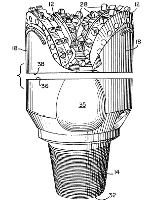
Referring to the drawings, Figure 1 illustrates,
in broken side perspective view, a rock drill bit 10
which can be remanuf actured according to the present
invention. Although the rock drill bit illustrated and
discussed herein has three cones 12, the method of the
present invention is applicable to a drill bit having
two cones. A threaded drill stem connector 14, which
is located at the opposite end of the bit from the
cones 12, is shown in the drawings as if it was
positioned at the bottom of the drill bit~ In
operation, however, the cutting cones 12 would be
located below the threaded connector 14 so that the
lowermost portion of the assembled drill bit would be
cones. The threaded connector 14 is engaged by a
correspondingly threaded drill string or stem (not
shown) which extends upwardly from the bottom of the
bore hole being drilled by the bit 10 to the earth's
surf ace .
The threaded connector 14 is part of the bit body
16, which supports three substantially i dentical leg
- 8 -
extensions 18, which, in turn, support the three cones
12. The bit body 16 is caused to rotate about a
central axis by the drill stem during drilling
operations. Each leg e~tension 18 include~ an outer
shirttail portion 20 which may be employed to form the
external annular gage surface of the bit. The
shirttail portion 20 additionally includes journal
mounting structure (not shown) which attaches a journal
22 to the bit leg extension. Each cone 12 is rotatably
mounted on a journal 22, such as is shown in cross-
section in Figure 1.
A lubricaticn supply source 24 for providing
lubricant to the journ~ bearing surfaces is contained
within the bit body 16 as shown in Figure 1. A passage
26 formed in each leg extension 18 provides fluid
communication between the lubrication supply source 24
and the journal bearing surfaces to assure proper
lubrication of these bearing surfaces during drilling
operations.
Each cone 12, which is rotatably mounted on a
journal 22, includes cutting teeth 28 which are
arranged on the outer surface of each cone in
circumferential rows so that the surface of the cone
may contain several rows of teeth. The rows of teeth
of adjacent cones must be spaced so that optimum
intermeshing and interaction of the teeth can occur as
the cones rotate on their journals during drilling.
The pattern and location of the teeth 28 is unique for
each cone so that these cutting structures will
disintegrate the rock formation as the bit is rotated
within the hole. The material from which the cutting
teeth 28 are formed will directly affect the useful
life of the rock drill bit 10. If a single tooth
breaks or becomes very worn, the remaining teeth will
be overloaded and wear more quickly. Therefore, it is
preferred to employ teeth formed ei~her from sintered
tungsten carbide alone or tungsten carbide combined
. ,
- 9- ~z~
with other alloys. These tungsten carbide teeth are
very expensive; however, until the present invention,
they were discarded with the rest of the worn-out bit,
even though many of them were not worn.
The bit body 16 further includes a centr~ channel
30 coextensive with the axis of rotation and the
central longitudinal axis of the drill bit which
communicates at one end through a port 32 with the
drill stem (not shown) and which may terminate at the
opposite end in a plurality of jet nozzles 34, only one
of which is shown in Figure 1. Drilling fluid can then
enter the bit body from the drill stem (not shown)
through port 32 and pass downwardly through channel 30
to be discharged through nozzle 34. Nozzle housing 35
may be formed integrally with the bit body.
The cessation of drilling operations to replace a
worn and, thus, inoperative drill bit, as previously
mentioned, is usually a costly procedure. The present
invention can effectively reduce that cost by providing
a reconditioned drill bit which functions as reliably
as an originally manufactured drill bit. In addition,
the remanufacturing process described herein can be
adapted to be used to originally manufacture new drill
~its at a lower cost than is possible with other
manufacturing methods.
Figure 2 illustrates one reconditioning method in
accordance with the present invention. Each drill bit
to be reconditioned must be examined care~ully to
determine the extent of the wear or any other damage
caused by the stresses of drilling. The present method
should not be employed on a bit body which is worn or
dama~ed or the resulting reconditioned bit will not be
capable of reliable performance. Once it has been
ascertained that the bit body can be effectively
salvaged, the leg extensions 18 including the journ~ s
(not shown) and the cones 12 are separated from the bit
body 16 along a plane perpendicular to the centr~ axis
- 10~
of the bit body located at approximately the level of
the nozzles 34. Separation of the leg assemblies from
the bit body can be accomplished in a variety of ways.
However, is it preferred to sever the bit body from the
leq extensions with a horizontal band saw. Those
tungsten carbide teeth 28 which are salvagable and can
be reused are then removed from each cone 12, and the
leg assemblies are then discarded.
After the leg extensions, journals and cones are
separated from the bit body, the bit body is left with
a substantially flat surface 36 and has the
configuration shown in Figure 2 between surface 36 and
port 32. Surface 36 may be faced on a lathe to prepare
the bit body for reconditioning. The bit body surface
36 must be prepared, by machining, milling or in some
similar suitable way, to receive new leg extension and
journal assemblies. Any redrilling of the lubricant
supply passages, central channel or nozzle housing
which is required may be done at this point. Either
two or three new leg and journal assemblies will be
required to complete the reconditioning, depending upon
whether the bit has two or three cone cutters. Leg and
journal assemblies which will fit on the reconditioned
bit body are relatively easily constructed by
conventional methods. It is preferred to form these
structures by hot forging. Howerver, they may be cast
in one of several ways known to the art. The bit body
engaging surface 38 of each leg extension 18 must be
substantially flat and may require facing by machining,
milling or the like to correspond to surface 36 on the
bit body 16. The interface between surface 36 and
surface 38 should preferably be no more than .003
~o .005 inches apart during the attachment procedure to
achieve optimum attachment of the bit bod~ and leg
extensions. In addition, the leg extensions and
journals will need to be posi~ioned o:n the bit body and
~ igned so that the cones are in correct alignment and
intermesh properly. Since the parts to be ~ igned are
small, the alignment can be accomplished in large part
by the machining of the parts.
Mating surfaces 36 on the bit ~ody and 38 on the
leg extensions are secured by electron beam welding
techniques. A focused beam of electrons is applied to
irradiate s~rfaces 36 and 38 and melt them to form a
welded interface which can extend deeply between the
bit body and the leg extensions in the direction of
beam pene~ration. Since electron beam welds are
characterized by a depth of penetration which is much
larger than the width of the heat affected zone,
warping and distortion of the welded parts is
minimized. Consequently, ~ ignment o parts ~oined by
electron beam welding is easier to acbieve. As
discussed above, any gap between surfaces 36 and 38
should be less than about .004 inches for best welding
results.
New cones into which salvaged, reusable tungsten
carbide teeth have been inserted are then mounted on
the journals and aligned to complete the bit
remanufacture process. The reconditioned rock drill
bit thus produced provides a lower cost, reliable
alternative to the installation of a completely new
bit.
Figures 3, 4 and 5 illustrate another method of
reconditioning a rock drill bit according to the
present invention. In this embodiment a hollow milling
tool is preferably used to cut the leg assemblies from
the worn drill bit. A curved saddle bore 40 is ormed
beIow each leg extension to be substantially coaxial
with the center of rotation of each cone~ The axis of
rotation of the saddle bore 40 will be approximately
transverse to the axis of rotation of the bit body 16.
In Figure 3, two such saddle bores 40 are shown in
dashed outlane. All of the leg extensions and cones
would be cut away to form saddle bores as part of the
-- 12 --
remanufacturing proce~s. ~he saddle bores 40 are cut
~o that the attachment of a new leg extension and
journal assembly 42, as shown without a cone 12 in
Figure 4, will accurately locate the cone cutters at
the correct an~le and skew.
Figure 4 illustrates, in exploded perspective, the
position of leg and journal assembly 42 wi~hout a cone
prior to attachment to the bit body 16 as the assembly
appears viewed from the interior of the bit body from
central channel 30. The assembly 42 is formed with a
saddle engaging surface 44 having a radius of curvature
subtantialy equal to that of the saddle bore 40. The
forma~ion of the leg and journal assembly 42 can be
accomplished on turning equipment with a drilling
operation, which is a relatively simple, low cost
procedure. The saddle engaginq surface 44 of the leg
and journal assembly 42 can be attached to the saddle
bore 40 by electron beam welding techniques as
discussed above. Because the saddle bores are formed
to position the cutters accurately, only minimal manual
alignment of the parts is required, and the leg and
journal assembly complete with a cone and cutters can
be attached to the bit body in a fully assembled
condition.
Figure 5 illustrates, in side view, a leg and
journal assembly 42, illustrating the relationship
between journal 22, shirttail port 20, leg extension 18
and saddle engaging surface 44.
Although the remanufacturing method of this
invention has been described and shown with respect to
separating the leg extensions and related structures
either along a plane perpendicular to the bit axis of
rotation or by the generation of saddle bores, other
methods of removing the leg extensions which generate
surfaces of other geometries may also be employed. For
example, the leg extensions may be separated from the
bit body by generating a concave or convex conical
. - ` ': ':
.
- 13 -
surface, in which the central axis of the cone i~
coaxial with the axis of rotation of the bit. In
addition, surfaces of other configurations and
geometries, such as concave or convex spherical
surfaces, could be generated. However, the generation
of a surface having any configuration during the
separation of the leg extension from the bit body is
contemplated to fall within the scope of the present
invention.
The method of remanufacturing a rock drill bit
discussed in connection with Figures 3, 4 and 5 can
also be applied to the original manufacture of new rock
drill bits. The bit body 16, which is formed from a
single, integral piece of material can be produced by
casting or forging. The bit body thus produced would
be drilled and/or machined as required to form the
lubrication passages 26, drilling fluid channel 30,
nozzle housing 35, threaded connector 14 and saddle
bores 40. Leg and journal assemblies 43 would then be
turned and drilled, the cones 12 with teeth 28 ~ormed
and secured to assembly 42, and the complete leg,
journal and cone assembly attached to a saddle bore 40
by electron beam welding. An originally manufactured
rock drill bit produced as just described costs
significantly less to manufacture than the bits of the
prior art.
Moreover, use of the saddle bore formation
technique both to remanufacture and to originally
manufacture a rock drill bit greatly simplifies cone
and cutter alignment, thus substantially eliminating
drill bit wear problems caused by nonaligned cones.
Figures 6 and 7 illustrate one type o~ cone ~ignment.
In Figure 6 the position of the cones relative to each
other is shown diagrammatically. The direction of
rotation of the bit is indicated by the arrow 46, and
the center of bit rotation is shown at point 48. The
cones in Figures 6 and 7 have two or more basic cone
~ 2~
- 14 -
angles, none of which has its apex at point 48.
However, since the cones are f~rced to rotate about the
bit centerline 48, they slip as ~hey rotate and produce
a tearing, gouging action. Cone action can be
increased by offsetting the cone centerlines from point
48, as shown in Figure 6. FigurP 7 illustrates three
cones in the positions shown dia~rammatically in Figure
6, and demonstrates the intermeshing of the cutting
teeth 2~. If proper cone alignment is not achieved,
whether it is the offset type of alignmen just
discussed or a more centered alignment, breakage or
other damage to the cutting teeth co~d occur and lead
to premature bit failure. Cons~uently, it is critical
to achieve proper cone alignment while performing the
bit remanufacturing and manufacturing processes of the
present invention.
The present remanufacturing process has been
discussed with respect to its application to tungsten
carbide cutters. The principles described hereln may
also be applied to recondition o~her cutters, such as
those made of milled steel and having abrasion
resistant hard facings. In addition, while the
specific journal structure of the remanufactured bit
has not been described, it will be apparent to those
skilled in the art that the present methods are well
suited for reconditioning drill bits having any of the
commonly used journal structures. These meth~ds will
be equally successful when applied to journ~s having
ball bearings, to journals having annular thrust
members and to journals of any other construction.
Many other modifications and variations of the present
methods within the purview of the following claims will
be apparent to those skilled in this ar~
Industrial Applicability
The reconditioning and remanufacturing methods
will f~nd their primary application in the salvage and
- 1 5 ~ ~
reconstruction of rolling cone cutter rock drill bit~
of the kind employed by the petroleum industry to dig
bore holes intended ~o 1 ead to petroleum depo~its.
However, any drill bit of similar construction,
whatever its end use, can be effectively and
inexpensively reconditioned to provide a reliable
alternative to discarding a worn bit and replacing it
with a completely new one. In addition, the methods
described herein can be employed in the original
manufacture of a rock drill bit at a lower cost than is
currently possible with available original equipment
manuf acturing methods.