Note: Descriptions are shown in the official language in which they were submitted.
~ ~ lS
¦ POWER AND FREE ROLLER CONVEYOR
1 ¦ This invention relates generally to a power and free
2 ¦roller conveyor driven by a linear induction motor.
3 l
4 ¦ Power and free roller conveyor systems are well known
¦in the art. Such systems typically include a plurality of
~ ¦rotatable cylindrical rollers supported on a frame and defining
7 la conveyor path along which objects may be conveyed. At least
8 Isome of the rollers are powered in some way to cause them to
~ ¦rotate about their axes and thereby impart a driving force to
¦any object supported thereon to cause it to be conveyed in a
11 ¦desired direction.
12 ¦ In a typical prior art system, an object to be
13 ¦conveyed will move along the conveyor path until it engages an
14 ¦obstacle, such as a stop that is movable into and out o~ the
¦path of travel of the object. Once movement of the object has
1~ ¦been arrested, the rollers ~hat support the ~bject will stop
17 ¦turnlng, although the remaining powered rollers will continue
18 ¦ to rotate. Upon removal of the obstacle, the arrested object
19 ¦ will continue its movement and the previously stopped rollers
¦ again will rotate.
21 ¦ Most of the known power and free roller conveyor
22 ¦ systems utilize pulleys, sprocket wheels, or other mechanical
~3 ¦ drive transmitting devices coupled to the rollers to cause them
~4 ¦ to~rotate. The pulleys or sprocket wheels are driven continu-
25 ¦ ously by one or more electric motors via belts, chains, or the
¦ like. A clutch mechanism conventionally is incorporated
~7 ¦ between the driving pulley or wheel and each powered roller to
~8 ¦ enable the la~ter to stop turning while i~s pulley or wheel
continues rotating.
~0 Although such prior art constructions operate
31;~9~915
1 reasonably well for the purposes intended, a number of
2 disadvantages are inherent in them. For instance, the clutch
3 mechanisms can be complicated to manufacture, expensive to
assemble, and troublesome to maintain. Further, many of the
known constructions have rollers that are driven in one
~ direction of rotation and cannot easily be driven in the
7 reverse directionD In addition, many of the prior art systems,
particularly those that use chain drives, are noisy.
~ In one prior art construction some of the rollers are
powered by electrical induction motors of the kind wherein the
11 rollers themselves serve as the rotors for the motors. In this
12 construction only some of the rollers are provided with such an
13 inductive drive while many, if not most, of the other rollers
14 are not powered. This system suffers from many disadvantages
l~ that arise throu~h an apparent compromise in its design. On
1~ the one hand, providing a motor for each roller is costly and
17 possibly difficult to implement sinGe each motor will differ to
18 some extent from the others, thereby causing speed inconsisten-
19 cies, uneven power distribution~ and the like. On the other
hand, the failure to provide drive means for each roller may
21 cause the system to be underpowered and unsuitable for many
22 applications.
23 In another prior art construction a linear induction
motor is utilized to drive the conveyor, but the conveyor is
2~ not composed of rotatable rotors. In particular, the conveyor
2~ of this prior art construction has a secondary member of a
~7 linear inductive motor a~fixed thereto, and the primary member
~8 is mounted in a position in which it may interact with the
secondary member to impart linear motion thereto. ~lthough a
~0 number of different embodiments of such a s~stem have been
'~
- 2
~9~91~
1 suggested, none of them has made use of rollers.
2 Accordingly, the invention seeks to provide a power and
3 free conveyor that substantially avoids the deficiencies of the
4 prior art. In particular, such a conveyor should be relatively
quiet and efficient in operation, require minimal maintenance,
~ and provide drive power to all rollers as necessary while
7 enabling any of the driven rollers to stop turning when
8 movement of an object supported thereon is halted. Preferably,
~ s~ch a system enables an operator easily to reverse the
direction of rotation of the driven rollers and further enables
11 the operator to control the torque and the speed of rotation.
12 inally, such a system should be relatively easy to manufac-
13 ture, simple in construction, and relatively inexpensive in
14 omparison to the benefits attained. A conveyor constructed
ccording to ~he invention possesses all of these character-
1~ istics.
17 In one broad aspect, the invention comprehends a power
18 and free roller conveyor comprising a linear induction motor
19 having one primary and a secondary, constituted by a
lurality~of freely rotatable rollers together forming a length
21 f conveyor path. Means mount each of the rollers in spaced
22 relation longitudinally of the path for rotation about its own
23 axis and closely adjacent but spaced from the primary by an air
a4 gap. Means cyclically propagate magnetic flux in one direction
along the primary longitudinally of the path, the air gap
26 roviding clearance between the primary and each of the
~7 lurality of rollers and being sufficiently small that the
~8 ropagation of the magnetic flux results in an interaction
f flux and current between the primary and the plurality of
~0 ollers sufficient to effec-t concurrent rotation ln one
1 Z99~15
1 direction of the plurality of rollers.
2 A power and free roller conveyor constructed
according to the invention includes a linear induction motor
4 driving system. In addi-tion, the conveyor includes a plurality
of load bearing rollers each of which has a driver attached
~ thereto. The drivers function as secondary members that
7 cooperate with the primary member of the linear induction motor
8 to impart rotation to the rollers.
9 In the disclosed embodiments of the invention the
speed with which a magnetic wave is propagated along the
11 primary member can be adjusted to control the speed at which
12 the rollers rotate. If desired, the direction of propagation
13 can be reversed to enable the direction of rotation of the
rolle to be reversed.
~1
22
a4
26
~8
129gL915
1 ¦ In one embodiment of the invention each roller has a
2 ¦cylindrical driver which effects ro~ation of such roller. In
¦another embodiment of the invention each driver is tubular and
4 ¦has a plurality of circumferentially spaced, substantially
¦planar surfaces formed thereon. The use of such planar
~ ¦surfaces allows presentation of more mass in closer proximity
7 ¦to the primary member than is possible with a curvilinear outer
8 ¦surface. As a result, greater driving torque can be applied to
2 ¦each roller.
10 l
11 ¦ A conveyor constructed according to the invention is
12 ¦disclosed in the following description and the accompanying
13 ¦drawings, wherein:
14 ¦ Figure 1 is a fragmentary, side elevational view of a
¦typical section of the conveyor;
1~ ¦ Figure 2 is a sectional view taken on the line 2-2 of
17 ¦Flgure l;
18 I Figure 3 is a sectional view taken on the line 3-3 of
19 ¦Figure 2;
¦ Figure 4 is a fragmentary, isometric view of a typical
2~ ¦ roller and its driver; and
22 ¦ Figure S is a view similar to Figure 4, but
23 ¦ illustrating another embodiment of the roller and driver unit.
~4 1
25 ¦ A power and free roller conveyor according to the
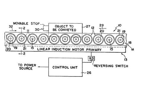
~B ¦ invention is designated generally by the numeral 10 and
~7 ¦ includes a plurality of rotatable load bearing rollers 11, a
~8 ¦ corresponding plurality of drivers 12, and the primary member
¦ 13 of a linear induction motor M.
~0 Each roller ll is cylindrical and is fixed to a shaft
- 4
!
1 ¦15 that projects beyond both ends of the roller. The shat at
2 ¦one end of the roller is journaled by bearings 16 in a frame
¦member 17 and the shaft at the opposite end of the roller is
¦journaled by similar bearings 16 in a second frame member 18
¦that is spaced from and parallels the frame member 17. Each
~ ¦roller thus may rotate freely about its own axis in response to
7 ¦the application of a driving force Each of the frame members
8 ¦17 and 18 is supported at a suitable level by conventional
~ ¦framework (not shown).
¦ The rollers and other supporting structure should be
11 ¦formed of appropriate material to provide adequate support for
12 ¦objects to be conveyed along a path, and the rollers themselves
13 ¦should be of appropriate diameter and length. Further, and as
14 ¦is shown in Figure 1, the rollers substantially parallel one
¦another and are sufficiently close to one another
lB ¦longitudinally of the conveyor path to effect the load
17 ¦ supporting and conveying tasks.
18 ¦ As is best shown in Figures 2 and 4, one end of the
19 ¦ shaft 15 of each roller extends beyond the adjacent frame
¦ member 18 and has fixed thereto one of the drivers 12. Each
21 ¦ driver is cylindrical, coaxial with its associated roller 11,
22 ¦ and preferably is o~ larger diameter than the latter. A cavity
23 19 may be ~ormed in each driver to reduce its weight and
a4 facilitate attachment to the roller shaft 15. Such attachment
may be effected by any known means, including various fasteners
2B or friction retention devices.
~7 Each driver 12 should be formed of electrically
conductive, non-magnetically permeable material, such as
aluminum or copper, in order to cooperate with the primary
~0 member 13 of the linear inductive motor as described below.
lZ~ 15
1 Each driver can be formed entirely of the non-magnetically
2 permeable material, or it can comprise a core 2~ formed of a
ba~e metal, such as steel, encircled by a closely fitting,
4 fixed sleeve 21 of aluminum or copper.
The primary member 13 of the linear induction motor
~ includes a core member 22 positioned within a housing and
7 composed, for example, of stacked, laminated, silicon-steel
8 strips having vertical slots 23 therein forming longitudinally
~ spaced poles 24 as is conventional. Coils 25 of electrically
conductive wire, such as copper, are wound on the core 22 and
~1 accommodated in the slots 23 in three-phase, multi-pole
12 configuration as shown in Figure 3. The coils 25 are alter-
nated with respect to their phase relationship so that, in a
14 direction longitudinally of ~he member 13, a phase 1 coil is
1~ followed by a phase 2 coil, a phase 2 coil is followed by a
1~ phase 3 coil, a phase 3 coil is ~ollowed by a phase 1 coil, and
17 so forth.
18 The particular primary member disclosed has a pole
19 pitch of about 5.715 cm (2.25 in.) and a length selected to
suit the needs of a particular application. The width of the
21 primary member preferably is less than the len~th of the
22 drivers 12, thereby enabling the latter to extend beyond
23 opposite sides of the primary as shown in Figure 2 to enable
~4 flux at opposite sides of the primary to be utilized.
~dditional information regarding the composition,
~B function, and operation of such a primary member can be found
~7 in an article entitled ~The Nature of Linear Induction Motors"
~8 and which appeared in Machine De~ maga7ine (August 23,
2~ 1984), which article is incorporated herein by reference.
~0 The primary member 13 of the linear induction motor M
- 6 -
~9~
1 should be positioned in close, overlying or underlying
2 proximity to the drivers 12, as is shown in Figure 2. However,
3 there should be sufficient space between the primary and the
4 drivers to provide rotational clearance therebetween, but such
space should not be so great as to prevent driving of the
~ rollers. In practice, a clearance or air gap of about 0.0889
7 cm (0.0625) or less is satisfactory. Larger clearances will
8 impair the efficiency o~ the system, and a clearance in excess
~ of about 0.635 cm (0.250 in.) may result in unsatisfactory
performance.
11 ~he use of drivers is not essential: the primary 13
12 could be positioned adjacent the rollers themselves. The use
of drivers, however, permits a variety of otherwise electric-
14 ally unsuitable materials to be us~d for the conveyor rollers
and also enables adequate driving torque to be obtained even in
18 those instances in which the diameter of the rollers may be too
17 small for optimum results.
18 An adjustable frequency and voltage control unit 26
19 couples the primary 13 to a source o~ power, such as three-
phase, 220 or 440V, 60Hz, AC power, and controls the ~requency
21 and voltage of power supplied to the primary member. A
22 suitable control unit is a Parajust GX AC motor speed control
23 manu~actured by Parametrics, Orange, Connecticut, and is
~4 coupled electrically to the primary member 13 in accordance
with conventional practice to vary the cyclical supply o~ power
~5 to the coils 25, and hence the speed with which a magnetic wave
~7 is propagated along the primary member 13. The control unit 26
28 also may incorporate a reversing switch RS o~ conventional
2~ construction to change the direction in which the magnetic wave
~O is propagated along the primary member 13. The control unit 26
- 7
lZ9~915
1 may be one which enables the driving torque imparted to the
2 rollers also to be varied by variation of the output frequency
3 o~ the control ~nit.
4 In operation, an object 27 supported on the conveyor
and of such length as to span two or more of the rollers 11 may
~ be conveyed along the conveyor in one direction or another by
q appropriate control of the linear induction motor M. As the
8 output o the control unit 26 effects propagation of a magnetic
8 wave in one direction along the primary member 13, an interac-
tion of magnetic flux and current between the primary member 13
11 and the secondary members, i.e., the drivers 12, induces
12 rotation o~ the rollers in one direction as is indicated by the
13 arrow 28 in Figure 4. Objects 27 supported on the conveyor
14 ¦ rollers 11 will be moved in the direction 29.
16 ¦ When an object 27 engages a stop or barrier 30 that is
1~ ¦movable into and out of the path of movement of the object,
17 ¦ movement of the latter will be arrested. The static weight o~
18 ¦the arrested object will prevent rotation of the rollers
19 ¦ directly supporting it. However, the remaining rollers will
¦ continue to rotate, thereby enabling other objects supported on
21 ¦ the conveyor to continue their movement.
22 ¦ If desired, the operator may adjust the control unit
23 ¦ 26 by means of the reversing switch RS to cause the magnetic
wave to be propagated in the opposite direction along the
primary member 13. This will cause the drivers 12 to rotate in
~B the opposite direction, as shown by the arrow 31 in ~igure 4,
~7 and thereby cause objects supported on the conveyor to move in
~8 the opposite direction 32.
The operator may adjust the frequency or voltage of
the output of the control unit 26 to control the rate o~
- 8
~z~
1 ¦propagation of the magnetic field, thereby controlling the
2 ¦speed and torque of the rollers 11.
3 ¦ ~n an alternative embodiment shown in Figure 5, the
4 ¦core 20 of each driver 12 is encircled by an electricall~
¦conductive, non-magnetically permeable sleeve 33 the periphery
~ ¦of which is provided with a plurality of circumferentially
7 ¦spaced, substantially uniform area planar surfaces 34. As a
¦ result, at a plurality of successive points in the rotation of
~ ¦ each driver a planar surface 34 will be parallel to the upper
¦ surface of the primary 13, thereby providing a substantially
11 ¦ greater surface area for exposure to the magnetic flux. This
12 ¦ relationship provides greater driving torque to the driver.
13 ¦ When using a driver like that shown in Figure 5 care
1~ ¦ should be taken to provide a sufficient number of p]anar
¦ surfaces to prevent the presence of too great an air gap
1~ ¦ between the driver and the primary when a planar surface
17 ¦ parallels the primary. The provision of eight such planar
18 ¦ surfaces appears to be an appropriate minimum.
19 ¦ The embodiments disclosed are representative of
¦ presentl~ preferred forms of the invention, but are intended to
2~ ¦ be illustrative rather than definitive thereof. The invention
22 ¦ is defined ~n the claims.
23
~4
~7
_ 9