Note: Descriptions are shown in the official language in which they were submitted.
8D-389 Canada
ROTATING SYSTEM CRITICAL SPEED
WHIRL DAMPER
ack~round of the Invention
This invention relates to ultracentrifuges and
particularly to speed dampers for ul-tracen-trifuges.
Still more particularly, this invention relates to a
solenoid-actuated ultracentrifuge damper that is
disengagable from the drive shaft when the rot~tional
speed attains a predetermined critical value.
Ultracentrifuges are used to separate liquid
materials of different densities and solids from liquids
by rotating a mixture of materials in a tube at angular
velocities of 100,000 revolutions per minute or more.
The material having the greatest density, and, hence the
greatest inertia will aggregate at the end of the tube
furthest from the axis or rotation. ~f a plurality of
materials of differing density are in the tube, they will
become arranged in descending order of density toward the
axis of rotation.
An important consideration in ultracentrifuge
design is the necessity of minimizing stresses upon
bearings used in conjunction with high speed components
such as the drive shaft that connects the rotor to the
driving mechanism. It is common pxactice in the design
and construction of an ultracentrifuge to make the drive
sllaft to have a relatively small diameter to provide a
degree of 1exibility in the drive shaft. Two primary
raasons exist for requiring flexibility in the drive
shaft.
First, when a user is operating an
ultracentrifuge rotor, it is very important to place test
samples so as to have a baIanced, symmetrical mass
distribution about the drive shaft. ~owever, perfect
balance is usually impossible; and even small variations
8D-389 Canada
--2--
have deleterious effects on the operational
characteristics of the ul-tracentrifuge system at angular
velocities typically achieved in such systems because the
cen-tripetal force on any given mass is proportional to
the square of the angular velocity. Even a very small
imbalance could cause vibrations that are capable of
applying damaging stresses to the high speed bearings
that are required to support the shaft. A slight flexing
of the d~ive shaft accommodates the imbalance and
prevents application of undesirable stresses to the
bearings.
A second reason for providing flexibility in the
drive shaft relates to slight geometric limitations
inherent in the machining processes used to form the
rotor shaft and associated drive mechanism. It is
impossible to construct an ideal drive shaft of uniform
density and diameter, because there are always tolerances
that must be allowed in forming the drive shaft.
Furthermore, it is also impossible to perfectly align the
drive shaft with the drive mechanism. Although
ultracentrifuge components are machined to be very nearly
perfect, the nature of the ultracentrifuging process is
such that the slightest imbalance or misalignment will
become apparent when the system is in use at high
rotational speeds. The usual ef-fect of an imbalance or
misalignment is unacceptable wear on the drive shaft
bearings, which as explained above is relieved by a
flexible drive shaft.
However, the use of a thin, flexible drive shaft
causes problems in the acceleration of the device to the
high speeds required. It is well-known that a thin,
elongate shaft rotating about its longitudinal axis has
certain natural frequencies of vibration that become
apparent at certain critical speeds. Ihe lowest critical
speed is a parameter of the centrifuge system and depends
primarily upon the shaft stiffness and the rotor mass.
8D-389 Canada
--3--
If only one end of the shaft is fixed, that end
is always a node, and the free end is always an antinode
at the resonant frequencies. In a typical
ultracentrifuge, the first resonance occurs at an angular
velocity of about 500 RPM. In general, the amplitudes of
tlle second and higher order resonances are out of the
operating speed range and have no effect upon the
efficacy of ultracentrifuging processes or upon the high
speed components of ultracentrifuge systems.
Ultracentrifuge operations require acceleration
of the drive shaft to speeds greater than the speed at
which the first resonance occurs. If the shaft is not
sufficiently stiff, stabilized, or damped, the
combination of vibrations caused by unbalanced conditions
from the test samples and the structure of the rotor and
the resonance may cause deflections of the shaft
sufficient to cause damage to the centrifuge and remix
the sample.
A possible solution to the difficulties caused
by imbalances and resonances in the system is to fix a
damper bearing on the thin drive shaft. Fixed dampers
must be designed for both low speed and high speed
operation and are, therefore, generally limited because
of the additional complexity of the dynamics of such
designs. Other attempts to solve the problems associated
with low speed resonances include journalling the shaft
in a plurality of bearings with the amount of bearing
surface engaging the rotating shaft being adjustable.
U.S. Patent 2,961,277, issued November 22, 1360
to Sternlicht discloses a bearing system in which a shaft
has a frustoconical journal portion intermediate the ends
of tlle shaft, which are supported on fixed bearings. A
bearing is mounted on an adjustable support to be movable
into or out of engagement with tlle frustoconical
journal. m e movable bearing is engaged with the journal
before the shaft reaches the critical angular velocity
8D-389 Canada ~2~3Ç;
and i5 disengaged from the shaft after the angular
velocity is greater than the critical value.
U.S. Patent No. 4,205,779, issued June 3, 1980
to Jacobson and assigned to Beckman Instruments, Inc.
assignee of the present invention, discloses an
ultracentrifuge drive system that includes a fixed damper
bearing. Jacobson discloses a cylindrical collar around
the shaft. A solenoid actuated bushing having a tapered
centering chamber is adapted to move into contact with
the collar to laterally support the rotor.
U.S. Patent No. 3,958,753, issued May 25, 1976
to Durland et al. discloses a centrifuge in which the
rotor is driven by an air jet and supported on an air
cushion. A solenoid moves a brake men~ber into engagement
with a friction bearing mounted on the bottom of the
rotor to decelerate the rotor and provide stability to
the rotor as it reduces its speed from a high rotational
speed to come to rest.
UOS. Patent ~o. 3,322,338 to Stallman et al.
discloses a centrifuge having a movable bearing assembly
carried by a frame that supports a rotatable member
coaxially with the axis of rotation of the rotor. The
rotatable member is movable between advanced and
retracted positions to engage and release -the rotor and
is formed to engage the rotor to hold it in a defined
axis of rotation. Stallman et al. further disclose means
for permitting the rotatable member to move laterally
within predetermined limits, thereby damping lateral
rotor movement a t critical transit ion speeds.
U.S. Patent ~oO 2,951,731 to Rushing discloses a
centrifuge having damping means including two sets of
concentric, spaced apart cylindrical sleeves. The
sleeves ar~ arranged to follow shaf-t vibrations and
overlap with other sleeves that are fixed with respect to
the shaft. A viscous liquid is reta ined between the
overlapping sleeves to damp out shaft vibrations.
~ 5
U.S. Patent No. 3,902,659 to Brinkman et al. discloses
a rotor stabilizing device having an upper bearing formed of
a first axially polarized magnetic ring and a second ring
including a ferrite material. One of the rings i5 secured to
the rotor, and the other ring is held stationary relative to
the rotor~ The rings are positioned such that oscillations of
the rotor cause eddy currents in an induction ring, which
absorbs the vibrations.
U.S. Patent No. 3~786/694 to Willeitner discloses a
damping device for a centrifuge rotor that is elastically
supported by hydraulic oil. The damping device comprises a
plurality of coaxial ring magnets and a disc that damp rotor
vibrations in the oil.
U.S. Patent No. 3,430,852 to Lenkey et al. discloses a
centrifuge rotor stabilizing device that frictionally contacts
the rotor to provide stability at critical speeds.
International application PCT/US83/00402 of Beckman
Instruments, assignee of the present application, discloses
a centrifuge stabilizing bearing that is actuated by a solenoid
in response to a specified rotational speed for engagement with
a bearing mounted to the rotor.
Summary of the Invention
The present invention overcomes the difficulties
associated with the complex dynamics of fixed damping systems
and the vibrational energy dissipation problems associated with
the devices that re~uire movement of a bearing relative to the
drive shaft to engage a bearing when it is necessary to damp
vibrations or to disengage the bearing after the critical speed
has baen surpassed.
LCM:mls
~2~
5A
Broadly speaking, the present invention provides
a method for damping transverse vibrations on a shaft
mounted centrifuge rotor wherein the rotor is concentrically
mounted to an axially extending drive shaft and rota-ted
thereby, comprising the steps of: placing a drive shaft
bearing on the shaft; placing a linearly movable bearing
assembly slidably movable in the axial direction along the
shaft, proximate the drive shaft bearing; actuating the
linearly movable bearing assembly to make low friction con-
tact with the drive shaft bearing for a predetermined angularvelocity range of the drive shaft; converting vibrations of
the drive shaft transverse to the axis of rotation of the
drive shat into lineax motion of the linearly movable bear-
ing assembly axially of the drive shaft by means of the low
friction contact; and dissipating energy associated with
linear motion of the linearly movable bearing assembly to
damp the transverse vibrations of the drive shaft.
The above method may be carried out by way of a
centrifuge system having a low speed vibration damping system
for dissipating transverse vibrational energy external to
rotating components of the system, comprising: a drive
shaft for mounting a centrifuge rotor concentrically to an
axial direction along the shaft; driving means for rotating
the drive shaft; a drive shaft bearing fixed to the drive
shaft; a linearly movable bearing assembly slidably movable
in the axial direction along the shaft, mounted adjacent
the drive shaft bearing; means for selectively engaging
the linearly movable bearing assembly and the drive shaft
~IF
Jt~ Sp: J ~ (
3~j
5s
bearing in low friction contact to convert vibrations of the
drive shaft in a plane transverse to the axis of rotation
thereof into linear motion of the linearly movable bearing
assembly axially of the drive shaft; and means for dissipating
energy associated with linear motion of the linearly movable
bearing assembly to damp the vibrations of the drive shaft.
~ he present invention is directed to a damper
system for a rotating device such as an ultracentrifuge that
comprises a rotor supported by a flexible drive
sp: ~! C ~'
~2~
8D-389 Canada
--6--
shaft connected to a motor by rigid support bearings.
The damper system includes a plunger that is
concentrically mounted upon the flexible drive shaft. A
plunger bearing is mounted to an end of the plunger for
selectively contacting a conical drive shaft bearing.
The drive shaft bearing is mounted to the drive shaft
near the plunger bearing. A magnetic solenoid actuates
the plunger to move the plunger bearing into contact with
the drive shaft bearing. The plunger applies a constant
force against the driveshaft bearing. The solenoid is
set to maintain low friction contact between the plunger
bearing and the drive shaft bearing for a predetermined
angular velocity range.
If the drive shaft tends to vibrate in a plane
perpendicular to the axis of rotation, the energy
associated with such vibrations is coupled from the drive
shaft bearing to the plunger bearing, which is fixed in
the plunger. Vibratory energy of the drive shaft is
therefore transformed into linear motion of the plunger,
which moves longitudinally relative to the solenoid. The
inner, generally cylindrical surface of the solenoid is
in frictional contact with the plunger such that
vibrational energy of the drive shaft is dissipated as
heat without damaging the ultracentrifuge system and
without substantially interfering with rotational motion
of the drive shaft. The system also shifts the critical
speed by changing the shaft stiffness.
Brief Description f the Drawings
Figure l is a vertical cross sectional view of a
centrifuge drive assembly including a disengagable
critical speed whirl damper according to the invention;
and
Fi~ure 2 is a simplified block diagram of a
control system for controlling the critical speed whirl
damper of Figure l.
f~
8D-389 Canada
--7--
Description of the Preferred Embodiment
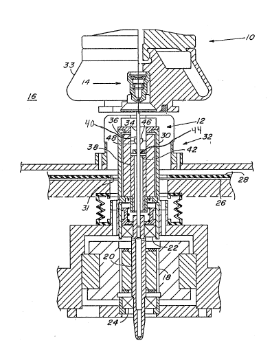
Referring to Figure 1, a centrifuge 10 includes
a drive spindle assembly 12 and hub assembly 14 that
projects from the drive assembly into a rotor chamber
16. m e drive spindle assembly 12 ~xtends downward from
the hub assembly as shown in the Figure 1 and is
connected to suitable drive means, such as an induction
motor 18. As shown schematically in the Figure 1, the
motor 18 includes an armature 20 mounted by an upper high
speed bearing 22 and a lower high speed bearing 24.
Suitable high speed bearings and motors are well-known in
the art so that the structural features of the motor 18,
the upper high speed bearing 22 and the lower high speed
bearing 24 are not explained in detail herein.
The motor 18 is mounted in a motor housing 26,
which as viewed in the Figure 1 is below a drive mount
plate 28. The drive spindle assembly 12 projects through
a passage 31 in the drive mount plate 28. m e rotor
chamber 16 is mounted to an end 30 of the drive spindle
assembly 12 that extends away from the motor 18 through
the passage 28. The hub assembly 14 is designed to mount
a rotor assembly 33 designed to contain a plurality of
test samples (not shown) in suitable containers for
centrifuging.
m e drive spindle assembly 10 includes a drive
shaft 34 extending between the armature 20 and the hub
assembly 14. The drive shaft 32 preferably has a
diameter that may be as small as about 0.078 inch. Such
shafts are typically employed in ultracentrifuge systems
fro driving a relat~ively small ultracentrifuge rotor 33
that may have a diameter as small as about 4 inches. The
small diameter drive shaft 34 is susceptible to ~lexing
and vibration since it serves as a coupling between the
hub 14 and the motor 18. In addition, as explained
above, the drive shaft 34 may be subjected to vibrations
8D~389 Canada
caused by rotor imbalance and limitations in the
machining steps involved in forming the cent:ri fuge 10.
A solenoid 36, which prèferably comprises a
plurality of turns of a suitably conduc~ing wire, is
fixed within the drive shaft housing 30 near the upper
end thereof. A plunger 38 is siidably mounted within a
~,~ cylindrical cavity 40 inside the solenoid 36, and a
~j plunger bearing 42 is fixed in ~ end 44 of the plunger
38. A low-speed drive shaft bearing 46 having a
frustoconical portion 48 facing the plunger bearing 42 is
fixed to the drive shaft 34 in proximity to the plunger
bearing 42.
The plunger bearing 42 may be selectively moved
along the axis of the drive shaft 34 into and out of
engagement with the frustocon~cal portion 48 of the drive
shaft bearing 46. Displacement of the drive shaft 34 in
a plane perpendicular to its axis of rotation brings the
frustoconical portion 48 of the low-speed drive shaft
bearing 46 into contact with the plunger bearing 42. The
force between the frustoconical portion 48 and the
plumger bearing 42 has a longitudinal component that is
generally aligned with the axis of rotation of the drive
shaft 34. This longitudinal force component causes the
plunger 38 to move within the solenoid cavity 40. me
force between the drive shaft bearing 46 and the ~plunger
bearing 42 has a radial component that .increase the
normal force between the interior of the solenoid 36 and
the outer sur face of the plunger 38. Friction between
the inner surface of the solenoid 36 and the outer
surface of the plunger 38 dissipates energy associated
with the translational motion of the plunger 38 relative
to the solenoid 36 and hence, also dissipates the
vibrational energy of the drive shaft 34.
Because the only contact between drive shaft 34
and the damping systems is via the low friction interface
of the frustoconical portion 48 of the drive shaft
8D-389 Canada
_g_
bearing ~6 and the plunger bearing 42, the vibrational
energy is dissipated without dissipating an appreciable
amount of rotational energy of the rotating portions of
the centrifuge system 10. This dissipation of
vibrational energy external to the rotating system
through a low friction contact with the rotating drive
shaft 34 is in contrast to previous damping systems that
rely upon relatively high friction contacts with the
drive shaft. Avoiding hiyh friction contact with the
drive shaft 34 prolongs the useful lifetime of the
centrifuge system 10 and results in increased operating
efficiency.
The plunger 38 should be formed of a material
that experiences a force when it is in a magnetic
field. It is well known that passing a direct electrical
current though a solenoid, such as the solenoid 36,
produces a static magnetic field having two opposing
poles like an ordinary bar magnet. The polarity of the
magnetic field of the solenoid 36 depends upon the
direction of the electrical current therethrough, and the
magnitude of the magnetic field depends upon the
magnitude of the current. m e plunger 38 includes a
material, such as iron or a ferrite, which experiences a
force when it is in a magnetic field. Therefore,
controlling the current in tl~e solenoid 36 provides means
for controlling the force between the plunger 38 and the
plunger bearing 42.
Accordingly, the centrifuge system 10 includes a
solenoid control system 50, shown in Figure 2, that is
coupled with the solenoid 36 by a pair of electrical
conductors 52 and 54 for providing electrical current to
the solenoid 360 The control system ~ includes a sensor
56 that outputs a signal indicative of the angular
velocity of the drive shaft 34. Suita~le speed sensing
techniques are well known in the art.
~ ~J'~ ~ 3
8D-389 Canada
--10--
The control system 50 is se-t to maintain the
plunger bearing 42 in close proximity with the low speed
drive shaft bearing 46 over a predetermined angular
velocity range of the drive shaft 34. The angular speed
range in which the solenoid 36, the plunger 38, the
plunger bearing 42 and the low speed shaft bearing 46
cooperate to damp low speed vibrations of the shaft 34 is
typically zero to about lOOO ~PM in mos-t ultracentrifuge
systems. Starting from the rest, the system provides
damping until the rotational speed exceeds ~he first
critical speed.
In operating the centrifuge lO it is necessary
to damp out vibrations of the shaft 34 that occur at low
speeds because such vibrations could have the detrimental
effects of disturbing materials separated from one
another in the centrifuging process or damaging the
centrifuge lO. It has been found that the critical speed
where resonances of the centrifuge system lO including a
very thin shaft 34 as described herein normally occurs at
less than lOOO RPM while the shaft 34 is either
accelerating from zero to its operational speed or while
the shaft is decelerating to a stationary position after
a centrifuging operation.
Therefore, as the motor 18 begins to operate to
accelerate the shaft 34, the control system 50 provides
electrical current to the solenoid 36 to move the plunger
bearing 42 into engagement with the frustoconical portion
48 of the low speed shaft bearing 46. The cen-trifuge
system lO thus is provided with vibration damping from
initial rotation of the drive shaft 34 until the angular
velocity of the drive shaft 34 exceeds a predetermined
value, typically about 550 RPM. Generally there is no
need for damping at rotational speeds above lOOO ~PM
since rubber drive housing mounts 58 provide adequate
damping at such speeds.
~2~3~
8D~389 Canada
--11--
The control system deactivates the damping
action by reducing the electrical current in the solenoid
to a value sufficient to permlt the weight of t.he plunger
38 to move the plunger bearing 42 out of engagement with
the low speed shaft bearing 46. After the centrifuge run
is complete and the shaft decelerates to the
predetermined angular velocity, the control system 50
again activates the solenoid to provide damping until the
shaft 34 comes to rest.