Note: Descriptions are shown in the official language in which they were submitted.
!'-~ , ,
SOFT SEAT FOR METERING VALVE
Background of the Invention
This invention pertains to the art of valves and
more particularly to metering valves~
The invention is particularly applicable to a new
5. and improved soft seat assembly for a metering valve and
will be described with particular reference thereto.
However, it will be appreciated that the invention has
broader implications and may be advantageously employed
in other valve environments and applications.
10. Previous metering valve arrangements, have typically
provided sealing engagement between the lower end of a
valve stem and a metallic valve seat defined on a
generally planar surface of a valve chamber. Although
the durable metal to metal contact between the stem and
15.seat provides adequate sealing for many applications,
the seat or an abutment area on the valve stem is
eventually subject to wear and degradation with
continued use over time. Irregularities that develop
between the mating metal surfaces of the stem and seat
20-inhibit precise sealing efforts.
More recent developments have attempted to employ a
soft seat that is designed for mating, sealing contact
with the valve stem. U.S. Patent No. 3,228,655 to Weise
issued January ll, 1966 is representative of one type of
25.valve assembly incorporating a soft seat. The Weise
patent particularly teaches a two-piece structure
defining a substitute seat surface comprising,
alternatively, a soft seat or hard seat. The substitute
seat is suitable for modifying an original valve
30.assembly in which a metal seat surface has become pitted
and worn. Further, the substitute seat i5 received in
the valve assembly without having to change or modify
any of the remaining valve components.
~z~
-2-
The substitute seat in the above-noted patent
necessarily requires a two-piece construction uhich is
sub ject to further problems. Mul~i-part components
require separa~e manufacture, tolerance specifications,
5 inventory, and, additionally, are prone to deleterious
wear between the cooperating members. ~loreover, any
movement of the substitute seat either during ~ssembly
or use, has an adverse effect on the metering function
and resul tant flow through the valve .
10. The present invention contemplates a new and
improved seat assembly which allows all of the benefits
of the prior construction to be realized while
eliminating the above-referred to problems and others.
15. Summary of tne Inv ntion
According to the present invention, an economical
and rel iable metering valve construction which
incorporates a soft seat construction is provided.
In accordance with one aspect of the invention, the
20. metering valve includes a valve body having first and
second passages communicating with a valve chamber
formed therein. A bonnet member and valve stem are
received in the valve chamber, and the stem is mounted
for selective advancement and retraction relative to a
25. valve seat disposed in the valve chamber intermediate
the first and second passages~ A seat insert interposed
between the valve stem and seat includes a base portion
having an aperture extending therethrough for fluid
communication with the first passage. The base portion
30. includes a tapering ou~er wall portion adjacent the
radial outer peripheral edge to Eacilitate fluid flo~
therepassed to the second passage. The seat insert
further includes plural leg portions extending axially
4~1
--3--
outward rom the tapering wall portion for abutting
engagement with the bonnet member. Each leg portion is
disposed radially inward from ~he outer periphery of the
base portion to enhance fluid flow therearound.
5 According to another aspect of ths invention, each
leg portion has a predetermined peripheral width
dimension which is less than the cross sectional
dimension of the second passage. This arrangement
as,sures fluid flow to the second passage regardless of
10- the orientation of the seat insert in the valve chamber.
According to yet another aspec~ of the invention,
the valve stem includes a generally frusto-conical
portion adapted for annular band contac~ with the soft
seat insert. Alternatively, the valve components are
15- dimensioned so that the stem frusto-conical portion is
adapted for abutting engagement directly with the valve
seat in the absence of the sea~ insert.
The principal advantage of the invention is the
provision of a metering valve having a unitary seat
20. insert for enhancing sealab il ity.
Another advantage of the invention resides in the
total encapsulation of the seat insert in the valve
chamb er .
Yet another advantage is found in the improved flow
25. paths defined around leg portions of the seat insert for
establishing free fluid flow between the first and
second passages.
Still other advantages and benefits of the invention
will become apparent to those skilled in the art upon a
30- reading and understanding of the following detailed
description .
, 3
~Z~
Brief Description of the Drawings
The invention may take physical form in certain
parts and arrangements of parts, a preerred embodiment
of which will be described in detail in this
5, specification and illustrated in the accompanying
drawings which form a part hereof, and wherein:
FIGURE 1 is a cross-sectional view of the assembled
metering valve formed in accordance with the invention
illustrating both open and closed positions of the valve
10. s tem;
FIGURE 2 is an enlarged, exploded detail of the
lower portion of the valve stem, the seat insert, and
the valve chamber;
FI~URE 3 is a plan view of the sub ject new seat
15. insert; and,
FIGURE 4 is a cross-sectional view of the lower
portion of the new metering valve in a closed position
showing the manner of valve sealing in the absence of
th e s ea t ins er t .
.:
20, Detailed Description of the Preferred Embodiment
Referring now to the drawings wherein the showings
are for purposes of illus trating the preferred
embodiment only and not for purposes of limiting same,
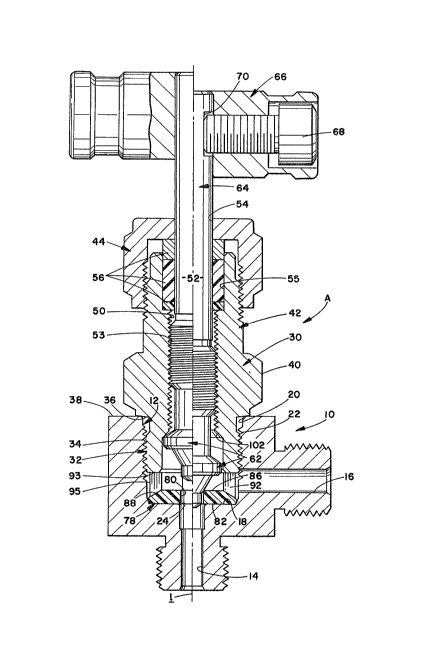
FIGURE 1 shows an assembled metering valve A having a
25. valve body 10 which may be used in a valve manifold
environment or in other types of valve assemblies. The
body includes a valve chamber 12 that commlmica~es with
a first or inlet passage 14 and a second or outlet
passage 16, although the inlet and outlet passages may
30. be reversed in certain appl ications . As shown, the
first passage coaxially communicates with valve chamber
12 at a radially disposed chamber inner end wall or
,
shoulder 18. The valve chamber further includes a
generally cylindrical sidewall 20 having a threaded
portion 22 spaced from end wall 18 adapted to receive a
valve bonnet member therein. A valve seat 24 is defined
5- generally at the area of intersection be~ween the valve
end wall and the first passage 14.
A valve bonnet member 30 includes a first or inner
end 32 cooperatively received in the valve chamber.
Specifically, threaded exterior portion 34 adjacent the
10~ bonnet inner end engages threaded portion 22 of the
valve chamber. A generally radially extending shoulder
36 is brought into abutting engagement with an outer
surface 38 of the valve body for positively defining
innermost receipt of the bonnet member in the chamber.
15- The advantageous function provided by the abutting
rela~ion will be described in greater detail
hereinbelow. Means to facilitate ease of threaded
insertion of the bonnet member 30 into the valve chamber
may be provided, e.g., wrench flats 40 or the like, on
20- an exterior surface of the bonnet member. ~ second or
outer end 42 of the bonnet member is s tructured to
threadedly receive a bonnet nut 44 thereon.
An elongated opening or bore 50 extends axially
through the bonnet member and is adapted to threadedly
25- receive a valve stem 52 as a~ 53 over an axial or
longitudinal extent of the stem. Similarly, an opening
54 is provided in the outer end wall of the bonnet nut
allowing outward passage of the valve stem
therethrough. Suitable packing means generally
30- designated 56 is interposed between the valve stem
exterior surface and an enlarged area 55 of the bore 50
adjacent the outer end 42 of the bonnet member. The
packing means is of a conventional, known type and
prevents fluid in the valve chamber from exi~ing the
valve around the stem. As is also known, the packing
means is axially dimensioned so that advancement of the
bonnet nut onto the bonnet member axially and radially
5- compresses the packing means into increased or more
positive sealing engagement between the ~alve stem and
bonnet member. Since packing means of this type are
known in the art and since the details thereof do not
form part of the present invention, a further detailed
10~ description thereof is deemed unnecessary.
The valve stem 52 includes a first or inner stem tip
end 62 disposed in the ~alve chamber 12 for selective
regulation of fluid flow between ~he first and second
passages 14, 16. The valve stem further includes a
15- second or outer end 64 having convenient actuating means
such as handle 66 disposed thereon. In the preferred
embodiment shown in FIGURE 1, the handle includes cap
screw means 68 extending into engagement with a flat 70
on the valve stem for maintaining the handle in
20- non-rotative relationship therewith. Therefore, manual
rotation imparted to the handle, in ~urn, rotates the
valve stem relative to the bonnet and the threaded
engagement between these members at area 53 provides
axial advancement and retraction of the stem in the
25- valve chamber as is well known in the art.
With continued reference to FIGURE 1, and with
reference now also to FIGURES 2 and 3, the subject
metering valve further includes a seat insert B.
Preferably, the seat insert includes an annular base
30- portion 78 having a central opening 80 therethrough.
The opening 80 is located to be concentrically aligned
with the inlet passage 14 and the stem axis 1. The base
portion further includes a first or inner surface 82
/
--7--
adapted for a facing, close mating relationship with
valve chamber inner end wall 18. A second or outer
surface 84 of the base is generally spaced Erom the
first surface and is comprised of two components. That
5- is, the surface 84 has a cen trally disposed, generally
planar portion 86 and a tapering, radially outer
band-l ike portion 8B interposed between planar portion
86 and an outer peripheral or circumferential surface
90. The tapering band-like portion B8 forms an enlarged
10. diameter flow passageway to better acilitate fluid flow
from the inlet to the outlet passage as will become more
apparent hereinbelow.
A pluralality of circumferentially spaced apart leg
portions 92 extend generally axially outward from the
15- outer surface 8~ of the seat insert at the area of the
tapering surface portion 88. The leg portions have a
length or axial dimension which is sufficient for
allowing the outer free ends thereof to be abuttingly
engaged as at 93 by the innermost portion oE bonnet
20- member inner end 32. Such rela tionship securely retains
the seat insert against rotational and axial movement in
the valve chamber wi th inner surface 8~ of the insert
base portion in close engaging relation with valve
chamber end wall 18. Purther, the base portion is
25. dimensioned and configured so that the outer peripheral
surface 90 of the base portion is closely received by
- the chamber sidewall 20. In the preferred embodiment, a
chamfered zone 94 defines the area of interface between
the chamber side and end walls. Close receipt of the
30- seat insert in the valve chamber in the manner described
provides total encapsulation to potentially el iminate
movement of the insert B.
9~g~
--8--
The leg portions 92 are typically equiangularly
spaced apart around the insert outer surface 84, and
four such legs 92 are contemplated in the preferred
embodiment here under discussion. However ~r it will be
5- appreciated that a greater or lesser number of legs
could also be used as deemed necessary and/or
appropriate. Additionally, the leg portions are spaced
radially inward by some predetermined dimension d from
the outer peripheral surface 90 of the base portion.
10. This radial spacing provides an annular gap 95 tFIGURE
1) between the outer surfaces of the leg portions and
the valve chamber sidewall 20 so that fluid may freely
flow therearound. Similarly, the leg portions 92 are
spaced radially outward from the cen~ral opening 80 by a
15. distance which is adequate to prevent any interference
with the valve stem 52.
With particular reference to FIGURE 2, the leg
portions 92 have predetermined peripheral or width
dimensions t which are less than the cross-sectional
20- dimension of the outlet passage 16. In this manner,
fluid may freely flow therearound to the annular gap 95
and, eventually, to the outlet passage 16. This
dimensional relationship advantageously dispenses with
any necessity for any particular rotational alignment of
25. the seat insert in the valve chamber. During assembly,
the seat insert may be placed in the chamber wi~hout
regard to the relative positioning between the leg
portions and outlet passage 16. Even if one of the leg
portions is situated directly in front of the outlet
30. passage, the flow of fluid is in no way hampered since
the leg portions all have a peripheral or width
dimension which is less than the cross-sectional
dimension of the outlet passage.
, ~ , 3
The sea~ insert B is formed of a non-metallic
material such as a plastic. Preferred examples of
suitable materials include HALAR~ a trademark of Allied
Corporation, a New York corporation~JDELRIN, a trademark
5- of E.I DuPont de Nemours and Compa ~ , a Delaware
corporation, and TEFLON, also a trademark of E.I. DuPont
de Nemours and Company, although it is readily apparent
that other materials exhibiting similar properties may
be used with equal success. The plastic construction
10. defines a so-called "soft" seat insert in comparison to
the "hard" metallic seat 24. Radial and axial
encapsulation o the seat insert as described positively
maintains the seat insert positioned between the valve
seat 24 and the bonnet member 30. Gross deformation of
15- the seat insert is successfully avoided by this total
encapsulation.
A radially outward extending frusto-conical portion
96 is provided on the stem inner end 62 for sealing
engagement with the seat insert. Since the seat insert
is formed of a soft material, annular band contact
between the frusto-conical portion 96 and the seat
insert is possible. A stem throttling portion 98
extends axially outward from the frusto-conical portion
for receipt in the inlet passage 14 during valve
25. closure. Further, a radially extending flange 100 is
advantageously provided adjacent the large diameter end
of frusto-conical portion 96. The flange and an
interior chamfered surface 102 on ~he bonnet member
cooperate to define a positive stop means for limiting
30- opening movement of the valve stem.
The metering valve A incorporating the soft seat
inser~ enhances the life of the valve. The valve stem
frusto-conical portion advantageously seals with either
the metal seat 24 or the seat insert B for regulating
~-- / --
9-i~
-10 -
fluid flow between the inlet and outlet passages.
Addi tionally, the leg portions of the seat insert allow
~otal encapsulation of the insert without any adverse
affect on fluid flow.
If the seat insert is removed for maintenance or
replacement, the remaining portions of the metering
valve are unaffected. In other words, the bonnet member
is designed to abuttingly engage the valve body outer
surface 38 along radial shoulder 36 with or without the
10. presence of a seat insert in the valve chamber. ~ly
the extent of axial advancement of the valve stem is
altered, and this movement is accommodated by
predetermined design characteristics incorporated into
the cooperating stem and valve bonnet threaded
15 portions. With reference to FIGURE 4, the sub ject new
metering valve is shown with the seat insert B removed
therefrom . It is apparent that the frus to -conical
portion 96 is designed for metal-to-metal abutting
contact with the valve seat 24. Thus, regulation of
20- fluid flow between the inlet and outlet passages can
proceed satisfactorily in the absence of the seat
insert. Sufficient axial advancement capability of the
valve stem into the chamber is provided so that
appropriate contact between the stem and valve seat may
25. be readily achieved.
The invention has been described with reference to
the preferred embodiment. Obviously, modifications and
alterations will occur to others upon a reading and
understanding of this specification. It is intended to
30. include all such modifications and alterations insofar
as they come within the scope o the appended claims or
the equivalents thereof.