Note: Descriptions are shown in the official language in which they were submitted.
WIRE MESH PRESS FACE COVER
Background of the Invention
1. Field of the InvPntion
This invention relates to press bending, and in particular to
an improved cover for a mold press face, especially for molds forming
complex and complicated shapes in hot glass sheets.
2A. Technical Considerations
Press bending is a well known shaping technique used in forming
glazing units that require precisely defined curvatures dictated by the
shape and outline of the glazing frame, for example, automotive windows.
Press bending of glass sheets as disclosed in U.S. Patent No. 4,197,108
to Frank et al and U.S. Patent No. 4,508,556 to Bennett et al, is usually
performed by heating the glass sheet to its heat softenlng temperature,
conveying the heat soEtened glass to a position in a shaping station
between upper and lower glass shap:lng members having complementing
shaplng surfaces, sandwiching the glass sheet between the shaping members
to impart the desired shape, removing the shaped glass sheet from the
shaplng station and rapidly cooling the shaped glass to impart at least a
partial temper. In the case of press bending heat soEtened glass sheets
in a lehr as disclosed in U.S. Patent No. 4,260,409 to ~eese et al, the
glass sheets are placed on a support carriage that is conveyed through a
heating lehr to effect a preliminary shape to the glass sheet by
grav-lty. After the preliminary shaping, a lower full
surface pressing mold lifts the glass sheets off the carriage and into
engagement with an upper full surface pressing mold to sandwicll the glass
~5~3~
sheets therebetween. The shaped glass sheets are then returned to the
carriage and conveyed through an annealing zone of the furnace.
The shaping members may be provided with a covering to protect
the glass sheet from the shaping member pressing surface. In particular,
the surEace of the hot glass sheet may get a "burn" mark if it contacts a
bare metal pressing surface. A stretchable knit fiber glass cloth is
commonly used to cover the pressing surface of the shaping member.
As automotive stylists continue to strive for more aerodynamic
designs with less drag and wind resistance, there is a demand for more
complex and compound shapes in automotive windows and windshields, such
as deep wraps and reverse curvatures. Fiber glass cloth may be used to
cover glass sheet shaping members, but the complexlty of these shapes may
cause excessive rubbing of the glass sheets against the cover during the
shaping operation, such that the cover wears out at a accelerated rate,
especially on concave shaping surfaces of the shaping member. Woven wire
screen has been used to help increase the useful life of the fiber glass
covers at high wear areas -ln surface areas of relatively simple
curvature, but this screen may tend to wrinkle when stretched across or
pressed against compound and/or complex shaping surfaces. The wrinkles
cause irregularities in the pressing surface that may be transferred to
the pressed glass sheets, causing optical distortion.
It would be advantageous to cover the shaping surface with a
cover that can protect the hot glass sheets from the surface of the
shaping member and conform to the complex and compound shaping surfaces
without wrinkling.
2B. Patents of Interest
.3~
U.S. Patent No. 3,248,968 to Cypher et al. discloses the use of
knitted fiber glass fabr-Lc as a mold cover for pressing molds in a
bending operation. As the mold contacts and presses the heat softened
glass sheet, the knitted fiber glass fabric deforms to provides a
resilient mold cover that also acts as an insulating layer between the
hot glass sheet and the mold face.
U.S. Patent No. 3,328,151 to Richerson discloses a wooden press
bending mold with a composite pressing surface. The pressing surface of
the mold includes alternating layers of woven glass cloth and aluminum
foil with an outer glass sheet contactlng surface of knitted fiberous
glass material.
U.S. Patent No. 3,420,652 to Seymour discloses a mold cover for
bending glass sheets. The useful life of a flber glass cover for a press
face is increased by superimposing a fine wire screen on the fiber glass
cloth at critical portions of the press face, such as areas of simple
curvature or portions of the mold that contact a painted portion of the
glass sheet. The screen is pulled aga-lnst the fiber glass cloth and mold
surface by a spring arrangement.
U.S. Patent Nos. 3,586,492 to McMaster and 3,741,743 to Seymour
disclose the use of wire mesh on a glass sheet support frame. In each
patent, the glass sheet engaglng surEace of a ring like support frame is
covered with at least one layer of wire mesh so that the heated glass
sheet contacts the mesh rather than the underlying steel support
structure. Seymour discloses the use of a fine wire mesh to contact the
glass supported by an underlying heavier wire mesh.
U.S. Patent No. 4,539,031 to Fecik et al, discloses an
apparatus for press shaping hot glass sheets. The pressing member
3~
includes a ring-like frame covered with insulating material that will not
mark the glass. The insulating material includes a wire screen embedded
between an upper and lower layer of nitryl rubber. As the upper layer
wears, it exposes the screen which will contact the glass sheet and
impart a mark that is visible on the glass sheet upon inspection, but
will not cause rejection of the shaped glass sheet.
An ob~ect of the presentdisclosure is to provide a temperature
resistant, wear resistant cover for a mold press face. The cover
includes a knitted wire mesh superimposed over an insulating material
layer. The knitted mesh may conform to the curved surface of the mold
during a pressing operation and maintains a smooth unwrinkled sheet
shaping surface. The knitted mesh may be stainless steel wire and the
insulating material may be refractory fiber paper. In one embodiment of
the invention the cover may include only the knitted wire mesh.
Another ob~ect ls to provide a mold for
pressing heat softened material including an insulat:Lng material
superimposed over the pressing surface of the mold and a knitted wire
mesh with interconnectlng wLre loops superimposed over the insulating
material. The knitted mesh is secured to strap members positLoned around
the periphery of the mold.
The knitted wire mesh provides a resilient, wear resisCant
covering that may deform co complex and/or compound curvatures of a
bending mold without wrinkling. Woven wire mesh which is formed of
straight wires in a rectangular weave cannot flex and deform to the
extend that knitted mesh can without forming a surface irregularity, i.e.
3;;~
wrinkle, which may be pressed into a heat softened glass sheet. The knitted
wire mesh provides a smooth pressing surface.
In accordance with one aspect of the invention there is provlded,
a mold cover for a heat soEtened sheet material shaping mold having a
complicated sheet shaping surface comprising:
a heat lnsulating material layer to thermally insulate said heat
softened sheet material from said shaping mold;
a wear resistant, knitted wire mesh stretched across said
insulating layer and said shaping surface to provide a durable contact
surface between said heat softened sheet and said insulating layer wherein
said cover substantially conforms to the complicated shaping surface of said
shaping mold while providing a smooth unwrinkled sheet shaping surface; and
means to secure said mesh to said mold wherein said mesh has
additional resiliency to stretch further and maintain said smooth,
unwrinkled sheet shaping surEace while secured to said mold and engaging a
heat softened sheet material.
In accordance with a second aspect of the invention there is
provided a mold for shaping heat softened sheets comprising:
a pair of opposing press faces each with a complementing
complicated sheet engaging surEace conEorming to the final shape of a said
sheet to be shaped;
an insulating materlal layer covering at least one of said sheet
engaging surfaces of said opposing press faces to thermally lnsulate said
heat softened sheet material from said sheet engaging surface;
a wear resistant, knitted wire mesh stretched across said
3~
insulating layer and said sheet engaging surface to provide a durable
contact surface between sald heat softened sheet and said insulating layer
wherein said insulating layer and said knitted mesh substantially conform to
said complicated sheet engaging surface of said at least one press Eace
while providing a smooth unwrinkled sheet engaging surface; and
means to secure said mesh to said at least one press face wherein
said mesh has additional resiliency to stretch further and maintain said
smooth unwrinkled sheet engaging surface while secured to said press face
and engaging said heat softened sheet.
In accordance with a third aspect of the invention there is
provided a mold for shaping heat softened sheets comprising:
a pair of opposing ceramic press faces each with a complementing
complicated sheet engaging surface conforming to the final shape of a said
sheet to be shaped;
a wear resistant, knitted wire mesh stretched across sai.d sheet
engaging surface of at least one of said press faces to provide a durable
contact surface between said heat softened sheet and said ceramic press face
wherein said knitted wire mesh substantially conforms to the shape of said
complicated sheet engaging surface of said at least one ceramic press face
while providing a smooth unwrinkled sheet shaping surface; and
means to secure said mesh to said press face wherein said mesh
has additional resiliency to stretch further and maintain said smooth
unwrinkled sheet shaping surface while secured to said press face and
engaging a heat softened sheet.
Embodiments of the invention will now be described with reference
- 5a -
~'
3~2
to the accompanying drawings wherein:
Figure 1 is a cross-sectional view of a lehr press bending
station, incorporating the press cover embodying the preserlt invention.
Figure 2 is a sectional view taken along line 2-2 oE Figure 1
showing the upper and lower pressing molds in their separated position and
covered with the mold press cover.
Figure 3 is a view similar to that of Figure 2, showing the glass
sheets lifted by the lower pressing mold into engagement wi-th the upper
pressing mold and the mold covers conforming to the pressing surfaces of the
upper and lower molds.
Figure 4 is an enlarged plan view showing a section of the
knitted wire mesh, illustrating its interlocking loop configuration.
Detailed Description of the PreEerred Embodiments
The present embodiments are presented with respect to their use
on the pressing surEaces of glass shaping members in a lehr press bending
arrangement as disclosed in U.S. Patent No. 4,260,409 to Reese et al, but it
should be understood that the invention may be used in any application where
a protective covering is required to maintain a wrinkle-free surface.
In a lehr bending operation as disclosed in U.S. Patent No.
4,260,409, glass sheets are loaded onto a plurality of mold support
carriages, conveyed through the heating lehr where the glass sheets are bent
by gravity to a preliminary shape, conveyed into a shaping station
- 5b -
3~
immediately beyond the gravity bending zone where the glass sheets are
pressed between upper and lower molds to impart the final curvature and
conveyed through an annealing ~one where the shaped sheets are cooled.
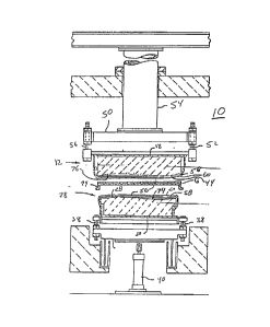
Referring to Figure 1 which shows a cross-section of a press station 10,
a plurality of mold support carriages 12 (one only shown in Figure 1)
extend transversely through lehr 14 and are conveyed through the lehr 14
by rotational engagement of stub rolls 16 with carriage rails 18. Each
stub roll 16 is mounted on a shaft that extends through a side wall of
the lehr 14 and is connected to a conveyor drive means (not shown).
Upright members 20 connect the rails 18 to a pair of upper horizontal
longitudinal rails 22, to which is mounted a glass sheet support rail
24. The glass sheet support rail 24 defines the curvature of the glass
sheet at a location slightly inboard of its perimeter.
With continued reference to Figure 1, the bending station 10
comprises a lower pressing mold 26 that includes an upper press face 28
whose upper surface covers a contlnuous area whose outline is slightly
smaller than the outline oE the support rall 2~ for reasons to be
discussed later. The press face 28 defines the final curved shape of the
glass sheet. In the particular embodiment of the lower pressing mold 26
as shown in Figures l and 2, the press face 28 defines a shape that is
concave in elevation across the width of the lehr to conform to a
longitudinal component of bend (see Figure 1), and is S-shaped in
elevation in the carriage conveying direction of the lehr 14 to conform
to a desired transverse component of bend. The pressing mold 26 rests on
a metal plate 30, and is held in alignment by pin and slot arrangement 32
similar to that disclosed in USPN 4,260,409 which locates and maintains
the geometric center of the press face 28 as the pressing mold 26
~3~i~3~
expands and contracts during heating and cooling. The metal plate 30 is
secured to reforcing frame 34, which is connected to a lower frame 36 by
vertical adjustment means 38, for example; by adjusting screws. A lower
piston 40 is connected to the lower frame 36 to raise and lower the lower
pressing mold 26 in a vertical directlon to positions controlled by the
stroke of the lower piston 40 and the adjustment of the ver~ical
adjustment means 38. When the lower piston 40 moves the lower'pressing
mold 26, the geometric center of the press face 28, moves along a fixed
vertical axis at the geometric center of the press bending station 10.
With continued reference to Figure 1, the press bending station
10 also includes an upper presslng mold 42 comprising a lower press face
44 that defines a downwardly facing shaping surface that complements the
upwardly facing shaping surface defined by the press face 28 of the lower
pressing mold 26. The upper pressing mold 42 is supported in a position
such that the geometric center of its press face 44 is intersected by the
vertical axis of movement for the geometric center of the press face 28
of the lower presslng mold 26, and so that the downwardly facing shaping
surface defined by the press face 44 is oriented and aligned over the
upwardly facing shaping surface defined by press face 28. A pin and slot
arrangement 46 similar to that on lower press mold 26 is used to maintain
the geometric center of the press face 44. The mold 42 is bolted to a
metal plate 48 and is ad~ustably secured to an upper metal frame 50
through vertical adjusting means 52 which may be similar in construction
to the vertical adiustment means 38. A vertical column 54 supported from
an overhead support structure and adjustable by screw jacks (not shown)
is used to hold the upper pressing mold 42 in a desired position.
The press faces 28 and 44 of the molds 26 and 42 respectively,
may be either ceramic as shown in Figures 1 through 3, metal, or any
other type of high temperature, wear resistant material. Each press face
includes a press cover 56 which embodies this invention. The
press cover 56 includes an insulating material layer 58, whlch acts as an
insulator between the hot glass sheet G and the press face to reduce the
amount of heat loss in the glass sheets during pressing. In addition,
the layer 58 should be sufficlently bulkly so as to act as a cushion to
absorb any small deEects in the press face surfaces or capture any
particles such as dust or glass chips on the press face and prevent these
irregularities from being transferred to the glass surface during
pressing and causing optical distortion. Due to the comple~ity of the
compound and/or complex curvature of the press faces 28 and 44,
insulating material layer 58 preferably has good tensile strength
flexibility so that it may conform to the press face surfaces. In one
particular embodiment of the invention, the insulating material layer 5B
may be a refractory fiber paper, such as material sold under the
tradenames of Cerafiber, Cerawool, or Pyrotek paper available from
Johns-~ansville, Colorado. Other materials, such as a fiber glass cloth
may be used for the layer 58.
The press cover 56 further includes a knitted wire mesh 60 to
cover the insulating macerial 58. The knitted feature of the mesh
material 60 allows it to be formed over the press faces. The knitted
mesh conforms to the compound and/or complex surfaces of the press faces
28 and 4~, and does not wrinkle as does woven wire screen, which includes
straight wires forming a rectangular weave, when forced to conform to
other than simple curvatures. The knitted mesh 60 is formed by
-- 8 --
3;~
interlocking loops 62 as shown in Figure 4, that can move relative to one
another and still retain relatively smooth and unwrinkled curved
surfaces. The knitted mesh 60 holds the insulating material 58, and
provides a more durable contact surface between the glass G and
insulating material 58.
In choosing the proper size mesh, several factors are of
importance. The mesh must be flexible to conform to the press face
surface without wrinkling, and resilient to withstand repeated loading
from successive pressing operations. In addition, the weave of the
interlocking loops 62 should be preferably "tight" enough i.e. have
closely spaced wires, so as to avoid any marking on the glass. An
increased number of wires in a given area will reduce the pressure on
each individual wire and thus lessen any marking due to the knitted
mesh. In a preferred embodiment, the knitted mesh 60 is made of .0045
inch (.114 millimeters) diameter wire with a mesh openlng of 14 to 16 per
inch. The wire is preferably made of 304 stainless steel wire, so that
it may operate for an extended useful life at the high temperatures to
which it ls sub~ected during the hot glass sheet pressing operation. The
knitted wire mesh is available from ~etex, New Jersey or ACS Industries,
Inc., Rhode Island.
Referring to Figures 1 through 3, the insulating layer 58 is
initially stretched across press faces 28 and 44 of molds 26 and 42,
respectively, and taped around the perimeter of the mold to hold it in
place. Knit wire mesh 60 is next stretched over the insulating layer 58
and secured to strap members 64, which extend around the perimeter of
each press by tack welding, clamps or any other well known attaching
arrangements.
32
In the pressing arrangement as shown in Figure 1, when the
carriage 12 which supports the heat softened, the preformed glass sheets
are positioned within the pressing station 10, lower mold 26 moves
vertica1ly upward through the outline of the rail 24 on carriage 12 to
lift the glass sheets off the carriage 12 and press it against the upper
mold 42. It is preferred that the lower mold 26 contact as much of the
glass G surface as possible so that proper contour of the glass sheets
may be effected as close to the edge of the glass sheet as possible. As
a result in the particular embodiment as shown in Figure 1, the strap 64
of the upper press 42 may be positioned outside the perimeter of the
press face 44, and supported by hangers 66 from back plate li8. On the
other hand, on lower press 26 the straps 68 are positioned within a
circumferential ledgé 70 beneath the press surface 28 of the mold 26 and
is supported by posts 72, so that the lower press 26 may extend as close
as possible to the rail 24 of the carriage 12 without any interference
from the straps 64 or posts 72.
Once the covering 56 is in position and the molds 26 and 42 are
sub~ected to a heated environment, for example a temperature range of
approximately 1000F to 1200F (538C to 649C) for a typical heating
lehr, the binder in the insulating material 58 may burn of, leaving the
refractory fiber of the insulating paper to coat the press faces. If
desired, the insulating material 58 may be glued to the press faces 28
and 44 by high temperature adhesLves.
It should be noted that in areas of reverse curvatures or
concave curvatures, such as areas 74 and 76 in lower and upper molds 26
and 42, respectively, the mesh 60 may not lay flat against the press
faces, but rather be slightly spaced from the press face when the molds
5~2
are spaced from one another as shown in Figure 2. This is due to the
inherent resiliency of the knitted wire mesh 60. The loops 62 (as shown
in Figure 4) may act as springs when subjected to a force. During the
presslng operation, when a glass sheet G is pressed between molds 26 and
42 as shown in Figure 3, the knitted mesh 60 will flex and stretch to
conform to the curvature of the press faces 28 and 44. After pressing,
when the molds are separated and load is removed, the knitted mesh 60 may
"spring back" and resume its original form as shown in Figure 2. Because
the knitted mesh 60 may be spaced from certain portions of the press
faces, it follows that in the upper press 42, the insulating material 58,
and especially the remaining refractory fibers of the insulating paper,
may also fall away from the press face 44 when the presses are separated
as shown in Figures 1 and 2. However, the knitted mesh 60 will continue
to support the material layer 58 relative to the press 42 so that during
pressing, the material layer 58 will be displaced back against the press
face 44 to insulate and protect the hot glass sheet G.
As stated earller, insulating material layer 58 acts as both an
insulator between the hot glass sheet and the press face, and as a
cushion to absorb any irregularities in the press surface and to capture
any small particles that may be on the press face. When the presses are
of ceramlc construction, the insulating property is not necessary, but
any alternative to the refractory paper on a ceramic press still must
function as a cushion and be reslstant to high temperatures. It is
believed that the knitted mesh 60 may be of sufficient thickness to
absorb any small irregularities in the press face and capture any small
particles that may form irregularities in the pressed glass surface so
that the mesh 60 may be used without the insulating material 58 on a
ceramic press face.
12~5~3Z
The forms of the invention shown and described herein,
represent ~ illustrative embodimen~, and it is understood that various
changes may be made without the departing from the scope of the
invention.
- 12 -