Note: Descriptions are shown in the official language in which they were submitted.
case 2990
-- 1 --
REFRIGERATOR DOOR TRAY ASSEMBLY
The present invention relates to a
refrigerator door tray assembly. More particularly, it
relates to a tray that is adapted to slide into a cavity
defined by the inner liner of the refrigerator door.
It is common to provide the inner liner of the
refrigerator door with a plurality of adjustable
shelves. The shelves are usually provided with male tab
members having a hook shape which are inserted into
openings between rungs of a ladder type bracket fastened
to the liner. The hook-like tab members cause the
shelves to be supported from the brackets in a
cantilever fashion that tends to result in the shelves
being wedged in position making this type of adjustable
shelving cumbersome to use as it usually requires two
hands to remove the shelf and reposition it within the
cavity of the liner. Further, the use of this type of
ladder bracket adds cost to the refrigerator.
Canadian Patent 631,401, issued
20 November 21, 1961 to Whirlpool Corporation provides a
boss that projects inwardly from the side walls of the
door liner. A shelf is provided that has a hook-like
upper part which wraps around the boss. The shelf
further includes a lip extending along the floor of the
shelf that is inserted into the rear wall of the liner.
The lip and hook of the shelf cooperate with the bosses
~ Case 2990
-- 2
and rear wall of the liner to support the shelf within
the cavity. Again, such an arranyement does not allow
for the easy insertion and removal of the shelf into the
cavity of the door liner.
Another type of refrigerator door tray
assembly is disclosed in Canadian Patent 979,96~ which
issued December 16, 1975 to Aeronutronic Ford
Corporation. The trays of this assembly may be inserted
into the cavity of the door liner defined between side
walls of the door liner. The side walls of the door
liner are provided with indentations in the liner into
which a plunger structure associated with the tray may
be inserted. The tray further includes flanges which
surround the ends of the forwardly projecting wall of
the door liner. These trays are of complex structure
which do not lend themselves to simple removal from the
cavity in the door liner and add cost of the
refrigerator.
While simplified refrigerator door shelf
assemblies are available, these assemblies have
disadvantages associated with them in that either the
shelf tends to become wedged in the door liner cavity
making its removal rather cumbersome or the shelf is not
properly secured within the cavity causing it to be
displaced from the door cavity liner upon forceful
closure of the door. One such assembly comprises a
door liner having elongated horizontally extending rails
projecting Erom the side walls of the liner. The
assembly further includes a kray having a floor adapted
to rest on the rails. These rails are provided with a
hook at their ends which fits into a corresponding
recess portion in floor of the tray so as to prevent the
tray from slipping out of the door liner. While such a
door liner provides for relatively easy insertion and
removal of the tray from the door, the tray tends to be
dislodged from the cavity when door is forcefully
Case 2990
_ 3
closed.
Another door tray assembly currently in use
has a door tray having a recess member in its side wall
which sits over a circular post projec~ing from the ~oor
liner into the cavity. The tray is held on the circular
post like projections by a button pressed out from a
vertical recessed groove in the side wall of the tray.
The button provides an interference fit with the end of
the post to secure the door to the posts within the
cavity of the liner. The tray is also provided with a
flange which engages the other edge of the wall of the
door liner only for the purpose of preventing tipping.
To effect removal of the tray from the door,
considerable force must be applied with both hands in
the vertical direction since the tray is held by means
of interference in the door liner. This removal is
cumbersome and could result in food spillage from the
tray during tray removal.
It is therefore an object of the present
invention to provide a refrigerator door tray assembly
wherein a tray may be readily inserted and removed from
the door without the use of brackets that have to be
secured to the liner.
I~ is a further object of the present
invention to provide a refrigerator door tray assembly
in which the tray may be readily inserted and removed
from the door but will be positively located within the
door such that it will not be dislodged upon forceful
closing of the door.
It is a further ob~ect of the present
invention to provicle a refriyerator door tray assembly
which may be moved within the cavity to facilitate tray
loading.
According to one aspect of the present
invention, there is provided a refrigerator door tray
assembly including a refrigerator door comprising an
~2~ 3 Case 2990
-- 4 ~
inner liner haviny a cavity defined by a rear wall and
two forwardly projecting supporting side walls. Each of
the supporting side walls includes opposin~ tray support
means which project from the side walls into the
cavity. The ~ray support means have an upwardly facing
ledge that slopes downwardly toward the rear wall at a
predetermined angle. The assembly further includes a
tray positionable within the cavity of the refrigerator
door. The tray includes a floor having two upstanding
side walls located adjacent the support ~alls of the
liner. The side walls of the tray each include
outwardly projecting arm means including a downwardly
facing surface that slopes downwardly at the
predetermined angle such that the arm means is adapted
to lie flush on the ledge of the support means. The
tray further includes positioning means for engaging the
inner liner to limit movement of the tray into the
cavity. The positioning means cooperates with the
downwardly facing surface of the arm means and the ledge
of the support means to positively locate the tray in
the cavity.
By providing an arm that slopes on the tray at
a predetermined angle equal to the sloping ledge of the
support means of the side wall, an effective mechanism
is provided for readily inserting the tray into the
cavity of the door liner without wedging the tray in the
cavity. The tray may be readily inserted by sliding the
arm means along the ledge as the tray is inserted :into
the cavity until the positioning means limits movement
oE the tray into the cavity. Alternatively, the tray
may be secured in the cavity by inserting the tray into
the cavity above the ledge until the positioning means
limits travel of the tray into the cavity and
subsequently lowering the tray onto the ledye. Further,
the assembly of the present invention does not re~uire
any further external members which have to be secured to
~5~ ~3
Case 2990
- 5 -
the liner such as a ladder type of supporting bracket.
The positioning means may comprise flanges
which project laterally from the tray to engage ends of
the side walls. These flanges may be formed in the side
walls of the tray. The purpose of the flanges is to
positively locate and to limit travel of the tray in the
cavity. The flanges cooperate with the sloping surface
of the arm of the tray and the sloping ledge of the
support means to positively locate the tray in the
cavity. The flush engagement is essential to the
present invention since a securing effect is provided
that evenly distributes the weight of the tray over the
length of the sloping surfaces. This securing effect is
different from that provided by the prior art which
commonly has an uneven weight distributed point-to-point
contact or wedging effect.
The tray may be further provided with an
upstanding rear wall and a lip which extends around the
side walls and the rear wall towards corresponding side
and rear walls of the liner. The lip further acts to
positively locate the tray within the cavity and
eliminate any excess space between the liner walls and
the tray. This allows for a more aesthetic fit between
the tray and the liner walls. It should be understood
that it is envisaged that the lip may form the
positioning means in one embodiment of the present
invention without recluiring lateral flanges formed on
the tray.
The projecting arm means of the present
invention may further include a securing arm portion
extending vertically downward from the downwarclly facing
surface of the arm means and a leading arm portion
extending horizontally from the securing arm portion.
The securing arm portion may co-operate with the
downward facing surface of the arm means during
insertion of the tray into the cavity and prevent the
removal of the tray from the cavity once inserted.
Case 2990
-- 6 ~
I~ should be undarstood that the predetermined
angle shoul~ be sufficient to allow the tray to be
positively held within the door cavity such that
force-ful closing of the door would not result in the
tray being dislodged while at the same time the angle
will provide proper support for the weight of t}le food
articles in the tray without resulting in the tray being
wedged in the cavity. Accordinyly, the tray can be
readily inserted and removed from the door liner due to
the even weight distribution of the arm of the tray over
the ledge of the side walls which allows for a sliding
engagement without wedging.
For better understanding of the nature and
objects of the present inventionf reference may be had
to the following diagrammatical drawings in which:
Figure 1 is a perspective view of a
refrigerator showing the refrigerator door tray assembly
of the present invention;
Figure 2 is and enlarged view showing the tray
and door liner of the assembly of the present invention;
Figure 3 is an enlarged perspective view of
showing the tray being positioned adjacent one side wall
of the inner liner;
Figure ~ is a partial view of one si~e wall of
the inner liner showing the support shoulder of the
present invention;
Figure 5 is plan view showing the tray
positively located by the side walls of the inner liner
within the cavity;
Figure 6 is a vi.ew of the tray and support
means ta~en along line VI-VI of Figure 5;
Figures 7 to ~ show one method of inserting
the tray into the cavity; and
Figures 10 and 11 show extreme angles at which
the leading edge of the slopes.
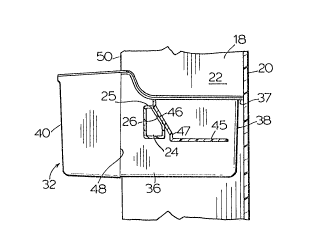
Referring to Figures 1 and 2, there is shown a
refrigerator 10 having a door 12 adapted to open and
3 Case 2990
- 7
close a compartment 1~ oE the refrigerator. The door 12
is provided with an inner liner 16. The liner 16
includes supporting side walls 18 which extend forwardly
of a rear wall 20 to define a cavity 22 therebetween.
The side walls 18 of the liner 16 are provided with a
plurality of shoulders 24 projecting from the side
walls 18 into cavity 22. The shoulders 24 constitute
the support means o~ the present invention. The
shoulders 24 are each provided with an upwardly facing
ledge 26. The ledge 26 slopes downwardly towards the
rear wall 20 of the liner 16 at a predetermined angle.
In Figure 4, this angle is shown at 28 to be an acute
angle with respect to vertical line 30. The acute
angle 28 is preferably 30. The door liner 16 is
vacuum formed with the shoulders 24 formed therein. The
shoulders 24 are shown to be spaced on each side wall in
a vertical direction to permit a plurality of tray
locations.
Each of the support means or shoulders 24 is
adapted to support a tray 32. Referring to
Figures 2, 3, 5 and 6, the tray 32 is provided with a
floor 34, upstanding side walls 36, a rear wall 38, and
a front wall 40. Skirting the upper portion of the side
wall 36 and rear wall 38 is a lip 37 which extends
towards adjacent side walls 18 and rear wall 20 of the
door liner 16. The upstanding walls 36 of the door tray
are provided with a support arm means or rib like
member 44. Rib like member 44 has a downwardly faciny
surface 46 which slopes at the same angle, acute
30 angle 28, as the ledge surface 26 of shoulders 24. Rib
member 44 includes a leading portion 45 that extends
substantially horizontally and acts to guide the tray
during insèrtion of the tray within the cavity.
Interposed between the leading portion 45 and the
downwardly facing surface 46 of the rib member 44 is a
vertically extending securing arm portion 47. While
Case 2990
-- 8 --
portion 47 is preferred in this embodiment oE the
invention, it should be understood that securing arm
portion 47 acts to further ensure that the tray is not
forced from the cavity during forcefu] closiny oE the
refrigerator door. The tray 32 further includes
flanges 48 (see Figures 5 and 6) which are adapted to
engage the ends 50 of the side walls 18 to limit the
movement of the tray into the cavity and cause the rib
arm portion 46 to lie flush on the ledge 26 of the
shoulders 24.
Figures 7 through 9 illustrate the most common
method of inserting the tray 32 into the cavity 22 of
the refrigerator door. The tray 32 is first positioned
with the horizontal leading arm portion 45 located on
the upper surface 25 of the shoulder 24 as shown in
Figure 7. The tray 32 may then be moved forward towards
the rear wall 20 of the cavity. As the corner, where
the horizontal portion 45 meets the securing vertical
portion 47, moves over the edge 26, the tray 32 will
fall due to gravity in the direction of arrow 80
(Figure 8) which is more or less consistent with the
angle 28 that the ledge 26 makes with the vertical
plane. The tray 32 will continue to be lowered into the
cavity until the flanges 48 on the tray engage the
ends 50 of the side walls 22. ~t this point as shown in
Figure 9 the tray will be positively located within the
cavity. It should be understood that the lip 37 of the
tray 32 may be dimensioned with respect to the side
walls 22 such that the lip also acts to locate the tray
in the cavity on the shoulders 24. In the supported
position shown in Figure 9, he surface 46 of rib 4~
lies flush against the upper surface 2fi of shoulder 24
and the entire surface of flange 48 lies flush against
the flat end wall surface 50. Due to the angle of the
surfaces 26 and ~6 the tray is positively located by the
side walls 18 of the inner liner 16. It should be
Case 2990
understood that the rib ~4 or its leadiny portion 45 do
not engage the rear wall 20 of the door liner 16.
Referring to Figures 4, 10 and 11, the
angle 28 should be sufficient to prevent the tray 32
from being displaced due to forceful closure O:e the
door 12. The anc31e should also be sufficient to
positively locate the tray in the cavity 22. For a tray
adapted to take a load in the order of 9 to 10 pounds,
the angle 28 is preferably 30. The preferred operable
range for this angle is from about 25 to 35. ~owever
with the addition of the securing arm portion 47, the
angle may be larger than 35 degrees. Figure ll show an
embodiment where the angle is less than 25. From
Figure 11 it is apparent that the steep sloping ledge 26
would result in the tray wedging into the cavity and
would also result in the tray being difficult to remove
from the cavity. Clearly, the embodiment shown in
Figure 11 is illustrative of an extreme angle 28 and is
not part of the present invention. In Figure 12, the
angle that the ledge slopes with respect to the vertical
is greater than 35 and may be subject to the problem of
the tray 32 being dislodged from the cavity during
forceful closure of the door in the event arm portion 47
does not act as a stop.
It should be understood that the angle is
determined by two fackors. The first factor is the
weight of the food in the tray. As the weight of the
food in the tray increases, the angle required to
maintain the tray in the cavity decreases because oE the
fact that the weight provides a greater downward force
which acts to positively locate the tray in the door.
The other critical factor in determinincJ the angle is
that, for a tray haviny no load or little or light load,
the angle must be sufficiently small so as to prevent
the door tray from being displaced as a result of
forceful closure of the door.