Language selection

Search

Patent 1295184 Summary

Third-party information liability

Some of the information on this Web page has been provided by external sources. The Government of Canada is not responsible for the accuracy, reliability or currency of the information supplied by external sources. Users wishing to rely upon this information should consult directly with the source of the information. Content provided by external sources is not subject to official languages, privacy and accessibility requirements.

Claims and Abstract availability

Any discrepancies in the text and image of the Claims and Abstract are due to differing posting times. Text of the Claims and Abstract are posted:

  • At the time the application is open to public inspection;
  • At the time of issue of the patent (grant).
(12) Patent: (11) CA 1295184
(21) Application Number: 1295184
(54) English Title: INK-DISPENSER COVER AND STAMP-INK CONTAINER FOR AN INKING SYSTEM
(54) French Title: COUVERCLE DE DISTRIBUTEUR D'ENCRE ET RESERVOIR D'ENCRE POUR MACHINE A AFFRANCHIR
Status: Expired and beyond the Period of Reversal
Bibliographic Data
(51) International Patent Classification (IPC):
  • B41K 03/60 (2006.01)
  • B41F 31/06 (2006.01)
(72) Inventors :
  • LEMBENS, HELMUT (Germany)
(73) Owners :
  • FRANCOTYP-POSTALIA GMBH
(71) Applicants :
  • FRANCOTYP-POSTALIA GMBH (Germany)
(74) Agent: SMART & BIGGAR LP
(74) Associate agent:
(45) Issued: 1992-02-04
(22) Filed Date: 1987-12-02
Availability of licence: N/A
Dedicated to the Public: N/A
(25) Language of filing: English

Patent Cooperation Treaty (PCT): No

(30) Application Priority Data:
Application No. Country/Territory Date
P 36 41 231.7-53 (Germany) 1986-12-02

Abstracts

English Abstract


Abstract
An ink-dispenser cover with a stamp-ink container for
franking and value-stamping machines is described this covers
the various chambers of the inking system such that even at high
rotational speeds, the ejection of the stamp ink from one
chamber and into another is inhibited. In addition, the stamp
ink can be replenished in a simple and clean manner, and without
opening the cover, by means of cartridges that can be inserted
into the cover.


Claims

Note: Claims are shown in the official language in which they were submitted.

THE EMBODIMENTS OF THE INVENTION IN WHICH AN EXCLUSIVE
PROPERTY OR PRIVILEGE IS CLAIMED ARE DEFINED AS FOLLOWS:
1. In an inking system of postage and valuation stamping
machines having an inking unit, the improvement comprising an ink
chamber, an overflow chamber separate from the ink chamber, a
transition region disposed between the ink chamber and the
overflow chamber, an inking unit cover having a portion covering
the ink chamber from above, said inking unit cover having a
stepped shape and a downwardly extending projection serving as a
drip edge at the transition region, said inking unit cover having
a funnel disposed on the portion of said inking unit cover
covering the ink chamber from above for refilling the ink chamber
with stamp ink, and a stamp ink container in the form of a
cartridge, said funnel including means for guiding, retaining and
opening said cartridge upon placement of said cartridge on said
funnel.
2. Inking system according to claim 1, wherein said means
for guiding, retaining and opening said cartridge includes a screw
connection between said cartridge and said funnel.
3. Inking system according to claim 1, wherein said means
for guiding, retaining and opening said cartridge includes a
pusher rod in said funnel for opening said cartridge and resilient
elements in said funnel for retaining said cartridge.

4. Inking system according to claim 1, wherein said
cartridge is in the form of a hollow cylindrical body including a
cylindrical discharge connection mounted on said hollow
cylindrical body and a lid integral with said hollow cylindrical
body for sealing said hollow cylindrical body.
5. Inking system according to claim 1, wherein said
cartridge is in the form of a hollow cylindrical body including a
cylindrical discharge connection mounted on said hollow
cylindrical body and a lid ultrasonically welded to said hollow
cylindrical body for sealing said hollow cylindrical body.
6. Inking system according to claim 2, wherein said screw
connection includes a threaded stem inserted into an opening
formed in said funnel and retained by ribs.
7. Inking system according to claim 6, wherein said
threaded stem is in the form of an obliquely cut-off hollow
cylinder.
8. Inking system according to claim 4, wherein said
discharge connection has an inner wall, said cartridge includes a
disk disposed between said hollow cylindrical body and said
discharge connection, and said disk has a periphery with a reduced
thickness being integrally joined with and formed of the same
material as said inner wall of said discharge connection.

9. Inking system according to claim 5, wherein said
discharge connection has an inner wall, said cartridge includes a
disk disposed between said hollow cylindrical body and said
discharge connection, and said disk has a periphery with a reduced
thickness being integrally joined with and formed of the same
material as said inner wall of said discharge connection.
10. Inking system according to claim 1, including hollow
cylindrical bodies attached to said cartridge for increasing the
effective volume of said cartridge.
11. Inking system according to claim 1, wherein said drip
edge has a wedge-shaped cross section.
12. Inking system according to claim 1, wherein said inking
unit cover has an upper portion above the ink chamber and a lower
portion above the overflow chamber, said drip edge being disposed
between said upper and lower portions.

Description

Note: Descriptions are shown in the official language in which they were submitted.


The present invention re:Lat~s to an ink-dispenser cover and
a stamp-ink container Eor an inking system used in franking ancl
value-stamping machinery.
Inking systems made up of an ink applicator, inking, and
ink transfer rollers that are powered by a common clrive system,
and are arranged in a housing together with a supply container
in which the ink transfer roller dips, the drive for which is
controlled by the pressure drum of the franking or the value-
stamping machine, respectively, are already known (DE-PS 33 16
558).
Such large inking systems for high-performance franking
machines have to have correspondingly large quantities of ink
available to them. This supply of ink for the machine has to be
replenished as soon as the level falls to a specific value that
is, for example, monitored and displayed by a monitoring device
in the rotating system. In all known franking machines, the
cover of the inking system has to be removed in order to
replenish the stamping ink, and the ink has to be poured in from
a supply tank. This replenishment also has to be carried out in
an appropriate manner when smaller inking systems are used.
Because of the uninterrupted rotakion of the ink transfer
roller, ink also yets onto the cover of the inking system, so
that replenishment by removal of the cover, ancd in particular
during the partial emptying of ink bottles, can lead to soiliny.

It is the task of the present invention to create an
ink-replenishment system ~hat is simple to operate and that makes
it unnecessary to open the inking system in order to repLenish it.
According to one asp2ct of the invention, thLs problem
is solved by in an inkLng system of postage and valuation stamping
machines having an inking unit, the improvement comprising an ink
chamber, an overflow chamber separate from ~he Lnk chamber, a
transition region disposed be~ween the ink chamber and the
overflow chamber, an inking unit cover having a portion covering
the ink chamber from above, said inking unit cover having a
stepped shape and a downwardly extending projection servlng as a
drip edge at the transltion region, said inking unit cover having
a funnel disposed on the portion of said inkiny unit cover
covering the ink chamber from above for refilling the ink chamber
with stamp ink, and a stamp ink container in the form of a
cartridge, said funnel including means for guiding, retaining and
opening said cartridge upon placement of said cartridge on said
funnel.
The invention is described in greater detail below on
the basis of the accompanying drawings in which,
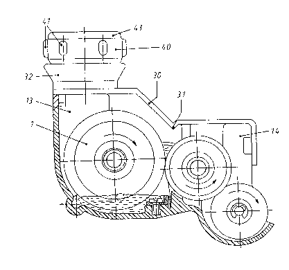
Figure :l shows the inking system including an ink-
dispenser cover;
Figure 2 i~ a cross-sectlon through the ink-d:Lspenser
cover;
Figure 3 i5 a side view and a partial section of a
cartridge; and

Figure 3a is an enlarged view of the portlon marked Z on
Yigure 3.
In all the figures, the same parts bear iclent;ical
reference numbers.
The ink-dispenser cover 30 is stepped so as to provide
optimal separa~ion of the various chambers from each other, this
being done to prevent the stamp ink being thrown into the acd~acent
chamber when the system is operated at high speed. In orcler to
increase rigidity and to form a drip edge 31 fox the stamp ink
that is thrown upward, the ink-system cover 30 is of wedge-shapecl
cross-section at the transition point from the ink chamber 13 to
the overflow chamber 14.
At that point where it covers the ink chamber 13 the
ink-dispenser cover 30 incorporates a funnel 32 that is formed in
one piece with said cover. Within the opening of the funnel and

held, for example, by three webs 33, there is a threaded stub.
This threaded st~lb 34 is configured at its upper end as an
obliquely-cut hollow cylinder 35. In addition, there are side
clamping tabs 15, and guide sur~aces 16, 17 to ensure a close,
matching fit of the ink-dispenser cover on the inking system; in
the interests of clarity, these are only shown in part in ~igure
1.
The funnel 32 serves to support, retain, and empty a
cartridge 40 that is filled with stamp ink. The cartridge 40 is
a cylindrical hollow body that has grip tabs 41 around its
periphery, that at one end has a similarly cylindrical outlet 42
and at its other end is closed off by a cover 43. The cover 43
seals the cartridge 40 comple-tely as a result of ~ltrasonic
welding. A disc 44 that is of reduced thickness at its edge is
installed as a separator or seal in Eront of the outlet 42,
which is provided with an internal thread. This disc is
connected by self-substance bonding with the inner wall of the
outlet 42. In order to replenish the inking system with stamp
ink, the cartridge 40 is screwed onto the threaded
stub 34 until the outlet 42 comes into contact with the webs 33.
The hollow cylinder then forces the ~isc 44 of the cartridge 40
up and the ink runs into the ink chamber 13 of the inking
system.
The inking-system cover 30 an~ the cartridge 40 are of
plastic.

5 1~
The cartridge 40 is made in various sizes so as to
accomodate various capacities. Figures 1 to 3 show an example
used for a small quantity of stamp ink. For larger quantities,
the cartridge ~0 can be made higher, for example, in that in
place oE the cover 43 an additional, preferably cylindrical,
hollow body of equal or greater volume can be installed on this
so as to be joined by self-substance bonding.
In place of the threaded connection between the funnel 32
and the cartridge 40, it is possible to use a plunger to open
the base of the cartridge 40 within the funnel, with the
cartridge 40 being held in place by a spring element.

Representative Drawing
A single figure which represents the drawing illustrating the invention.
Administrative Status

2024-08-01:As part of the Next Generation Patents (NGP) transition, the Canadian Patents Database (CPD) now contains a more detailed Event History, which replicates the Event Log of our new back-office solution.

Please note that "Inactive:" events refers to events no longer in use in our new back-office solution.

For a clearer understanding of the status of the application/patent presented on this page, the site Disclaimer , as well as the definitions for Patent , Event History , Maintenance Fee  and Payment History  should be consulted.

Event History

Description Date
Time Limit for Reversal Expired 2008-02-04
Letter Sent 2007-02-05
Inactive: IPC from MCD 2006-03-11
Grant by Issuance 1992-02-04

Abandonment History

There is no abandonment history.

Fee History

Fee Type Anniversary Year Due Date Paid Date
MF (category 1, 6th anniv.) - standard 1998-02-04 1998-01-22
MF (category 1, 7th anniv.) - standard 1999-02-04 1999-01-08
MF (category 1, 8th anniv.) - standard 2000-02-04 2000-01-13
MF (category 1, 9th anniv.) - standard 2001-02-05 2001-01-11
MF (category 1, 10th anniv.) - standard 2002-02-04 2002-01-21
MF (category 1, 11th anniv.) - standard 2003-02-04 2003-01-15
MF (category 1, 12th anniv.) - standard 2004-02-04 2004-01-12
MF (category 1, 13th anniv.) - standard 2005-02-04 2005-01-12
MF (category 1, 14th anniv.) - standard 2006-02-06 2005-12-09
Owners on Record

Note: Records showing the ownership history in alphabetical order.

Current Owners on Record
FRANCOTYP-POSTALIA GMBH
Past Owners on Record
HELMUT LEMBENS
Past Owners that do not appear in the "Owners on Record" listing will appear in other documentation within the application.
Documents

To view selected files, please enter reCAPTCHA code :


To view images, click a link in the Document Description column. To download the documents, select one or more checkboxes in the first column and then click the "Download Selected in PDF format (Zip Archive)" or the "Download Selected as Single PDF" button.

List of published and non-published patent-specific documents on the CPD .

If you have any difficulty accessing content, you can call the Client Service Centre at 1-866-997-1936 or send them an e-mail at CIPO Client Service Centre.


Document
Description 
Date
(yyyy-mm-dd) 
Number of pages   Size of Image (KB) 
Claims 1993-10-25 3 83
Abstract 1993-10-25 1 26
Drawings 1993-10-25 1 29
Descriptions 1993-10-25 5 133
Representative drawing 2000-07-13 1 17
Maintenance Fee Notice 2007-03-18 1 172
Fees 1997-01-28 1 75
Fees 1994-01-11 1 34
Fees 1996-01-08 1 41
Fees 1995-01-09 1 57