Sélection de la langue

Search

Sommaire du brevet 1295184 

Énoncé de désistement de responsabilité concernant l'information provenant de tiers

Une partie des informations de ce site Web a été fournie par des sources externes. Le gouvernement du Canada n'assume aucune responsabilité concernant la précision, l'actualité ou la fiabilité des informations fournies par les sources externes. Les utilisateurs qui désirent employer cette information devraient consulter directement la source des informations. Le contenu fourni par les sources externes n'est pas assujetti aux exigences sur les langues officielles, la protection des renseignements personnels et l'accessibilité.

Disponibilité de l'Abrégé et des Revendications

L'apparition de différences dans le texte et l'image des Revendications et de l'Abrégé dépend du moment auquel le document est publié. Les textes des Revendications et de l'Abrégé sont affichés :

  • lorsque la demande peut être examinée par le public;
  • lorsque le brevet est émis (délivrance).
(12) Brevet: (11) CA 1295184
(21) Numéro de la demande: 1295184
(54) Titre français: COUVERCLE DE DISTRIBUTEUR D'ENCRE ET RESERVOIR D'ENCRE POUR MACHINE A AFFRANCHIR
(54) Titre anglais: INK-DISPENSER COVER AND STAMP-INK CONTAINER FOR AN INKING SYSTEM
Statut: Périmé et au-delà du délai pour l’annulation
Données bibliographiques
(51) Classification internationale des brevets (CIB):
  • B41K 03/60 (2006.01)
  • B41F 31/06 (2006.01)
(72) Inventeurs :
  • LEMBENS, HELMUT (Allemagne)
(73) Titulaires :
  • FRANCOTYP-POSTALIA GMBH
(71) Demandeurs :
  • FRANCOTYP-POSTALIA GMBH (Allemagne)
(74) Agent: SMART & BIGGAR LP
(74) Co-agent:
(45) Délivré: 1992-02-04
(22) Date de dépôt: 1987-12-02
Licence disponible: S.O.
Cédé au domaine public: S.O.
(25) Langue des documents déposés: Anglais

Traité de coopération en matière de brevets (PCT): Non

(30) Données de priorité de la demande:
Numéro de la demande Pays / territoire Date
P 36 41 231.7-53 (Allemagne) 1986-12-02

Abrégés

Abrégé anglais


Abstract
An ink-dispenser cover with a stamp-ink container for
franking and value-stamping machines is described this covers
the various chambers of the inking system such that even at high
rotational speeds, the ejection of the stamp ink from one
chamber and into another is inhibited. In addition, the stamp
ink can be replenished in a simple and clean manner, and without
opening the cover, by means of cartridges that can be inserted
into the cover.

Revendications

Note : Les revendications sont présentées dans la langue officielle dans laquelle elles ont été soumises.


THE EMBODIMENTS OF THE INVENTION IN WHICH AN EXCLUSIVE
PROPERTY OR PRIVILEGE IS CLAIMED ARE DEFINED AS FOLLOWS:
1. In an inking system of postage and valuation stamping
machines having an inking unit, the improvement comprising an ink
chamber, an overflow chamber separate from the ink chamber, a
transition region disposed between the ink chamber and the
overflow chamber, an inking unit cover having a portion covering
the ink chamber from above, said inking unit cover having a
stepped shape and a downwardly extending projection serving as a
drip edge at the transition region, said inking unit cover having
a funnel disposed on the portion of said inking unit cover
covering the ink chamber from above for refilling the ink chamber
with stamp ink, and a stamp ink container in the form of a
cartridge, said funnel including means for guiding, retaining and
opening said cartridge upon placement of said cartridge on said
funnel.
2. Inking system according to claim 1, wherein said means
for guiding, retaining and opening said cartridge includes a screw
connection between said cartridge and said funnel.
3. Inking system according to claim 1, wherein said means
for guiding, retaining and opening said cartridge includes a
pusher rod in said funnel for opening said cartridge and resilient
elements in said funnel for retaining said cartridge.

4. Inking system according to claim 1, wherein said
cartridge is in the form of a hollow cylindrical body including a
cylindrical discharge connection mounted on said hollow
cylindrical body and a lid integral with said hollow cylindrical
body for sealing said hollow cylindrical body.
5. Inking system according to claim 1, wherein said
cartridge is in the form of a hollow cylindrical body including a
cylindrical discharge connection mounted on said hollow
cylindrical body and a lid ultrasonically welded to said hollow
cylindrical body for sealing said hollow cylindrical body.
6. Inking system according to claim 2, wherein said screw
connection includes a threaded stem inserted into an opening
formed in said funnel and retained by ribs.
7. Inking system according to claim 6, wherein said
threaded stem is in the form of an obliquely cut-off hollow
cylinder.
8. Inking system according to claim 4, wherein said
discharge connection has an inner wall, said cartridge includes a
disk disposed between said hollow cylindrical body and said
discharge connection, and said disk has a periphery with a reduced
thickness being integrally joined with and formed of the same
material as said inner wall of said discharge connection.

9. Inking system according to claim 5, wherein said
discharge connection has an inner wall, said cartridge includes a
disk disposed between said hollow cylindrical body and said
discharge connection, and said disk has a periphery with a reduced
thickness being integrally joined with and formed of the same
material as said inner wall of said discharge connection.
10. Inking system according to claim 1, including hollow
cylindrical bodies attached to said cartridge for increasing the
effective volume of said cartridge.
11. Inking system according to claim 1, wherein said drip
edge has a wedge-shaped cross section.
12. Inking system according to claim 1, wherein said inking
unit cover has an upper portion above the ink chamber and a lower
portion above the overflow chamber, said drip edge being disposed
between said upper and lower portions.

Description

Note : Les descriptions sont présentées dans la langue officielle dans laquelle elles ont été soumises.
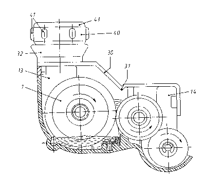

The present invention re:Lat~s to an ink-dispenser cover and
a stamp-ink container Eor an inking system used in franking ancl
value-stamping machinery.
Inking systems made up of an ink applicator, inking, and
ink transfer rollers that are powered by a common clrive system,
and are arranged in a housing together with a supply container
in which the ink transfer roller dips, the drive for which is
controlled by the pressure drum of the franking or the value-
stamping machine, respectively, are already known (DE-PS 33 16
558).
Such large inking systems for high-performance franking
machines have to have correspondingly large quantities of ink
available to them. This supply of ink for the machine has to be
replenished as soon as the level falls to a specific value that
is, for example, monitored and displayed by a monitoring device
in the rotating system. In all known franking machines, the
cover of the inking system has to be removed in order to
replenish the stamping ink, and the ink has to be poured in from
a supply tank. This replenishment also has to be carried out in
an appropriate manner when smaller inking systems are used.
Because of the uninterrupted rotakion of the ink transfer
roller, ink also yets onto the cover of the inking system, so
that replenishment by removal of the cover, ancd in particular
during the partial emptying of ink bottles, can lead to soiliny.

It is the task of the present invention to create an
ink-replenishment system ~hat is simple to operate and that makes
it unnecessary to open the inking system in order to repLenish it.
According to one asp2ct of the invention, thLs problem
is solved by in an inkLng system of postage and valuation stamping
machines having an inking unit, the improvement comprising an ink
chamber, an overflow chamber separate from ~he Lnk chamber, a
transition region disposed be~ween the ink chamber and the
overflow chamber, an inking unit cover having a portion covering
the ink chamber from above, said inking unit cover having a
stepped shape and a downwardly extending projection servlng as a
drip edge at the transltion region, said inking unit cover having
a funnel disposed on the portion of said inkiny unit cover
covering the ink chamber from above for refilling the ink chamber
with stamp ink, and a stamp ink container in the form of a
cartridge, said funnel including means for guiding, retaining and
opening said cartridge upon placement of said cartridge on said
funnel.
The invention is described in greater detail below on
the basis of the accompanying drawings in which,
Figure :l shows the inking system including an ink-
dispenser cover;
Figure 2 i~ a cross-sectlon through the ink-d:Lspenser
cover;
Figure 3 i5 a side view and a partial section of a
cartridge; and

Figure 3a is an enlarged view of the portlon marked Z on
Yigure 3.
In all the figures, the same parts bear iclent;ical
reference numbers.
The ink-dispenser cover 30 is stepped so as to provide
optimal separa~ion of the various chambers from each other, this
being done to prevent the stamp ink being thrown into the acd~acent
chamber when the system is operated at high speed. In orcler to
increase rigidity and to form a drip edge 31 fox the stamp ink
that is thrown upward, the ink-system cover 30 is of wedge-shapecl
cross-section at the transition point from the ink chamber 13 to
the overflow chamber 14.
At that point where it covers the ink chamber 13 the
ink-dispenser cover 30 incorporates a funnel 32 that is formed in
one piece with said cover. Within the opening of the funnel and

held, for example, by three webs 33, there is a threaded stub.
This threaded st~lb 34 is configured at its upper end as an
obliquely-cut hollow cylinder 35. In addition, there are side
clamping tabs 15, and guide sur~aces 16, 17 to ensure a close,
matching fit of the ink-dispenser cover on the inking system; in
the interests of clarity, these are only shown in part in ~igure
1.
The funnel 32 serves to support, retain, and empty a
cartridge 40 that is filled with stamp ink. The cartridge 40 is
a cylindrical hollow body that has grip tabs 41 around its
periphery, that at one end has a similarly cylindrical outlet 42
and at its other end is closed off by a cover 43. The cover 43
seals the cartridge 40 comple-tely as a result of ~ltrasonic
welding. A disc 44 that is of reduced thickness at its edge is
installed as a separator or seal in Eront of the outlet 42,
which is provided with an internal thread. This disc is
connected by self-substance bonding with the inner wall of the
outlet 42. In order to replenish the inking system with stamp
ink, the cartridge 40 is screwed onto the threaded
stub 34 until the outlet 42 comes into contact with the webs 33.
The hollow cylinder then forces the ~isc 44 of the cartridge 40
up and the ink runs into the ink chamber 13 of the inking
system.
The inking-system cover 30 an~ the cartridge 40 are of
plastic.

5 1~
The cartridge 40 is made in various sizes so as to
accomodate various capacities. Figures 1 to 3 show an example
used for a small quantity of stamp ink. For larger quantities,
the cartridge ~0 can be made higher, for example, in that in
place oE the cover 43 an additional, preferably cylindrical,
hollow body of equal or greater volume can be installed on this
so as to be joined by self-substance bonding.
In place of the threaded connection between the funnel 32
and the cartridge 40, it is possible to use a plunger to open
the base of the cartridge 40 within the funnel, with the
cartridge 40 being held in place by a spring element.

Dessin représentatif
Une figure unique qui représente un dessin illustrant l'invention.
États administratifs

2024-08-01 : Dans le cadre de la transition vers les Brevets de nouvelle génération (BNG), la base de données sur les brevets canadiens (BDBC) contient désormais un Historique d'événement plus détaillé, qui reproduit le Journal des événements de notre nouvelle solution interne.

Veuillez noter que les événements débutant par « Inactive : » se réfèrent à des événements qui ne sont plus utilisés dans notre nouvelle solution interne.

Pour une meilleure compréhension de l'état de la demande ou brevet qui figure sur cette page, la rubrique Mise en garde , et les descriptions de Brevet , Historique d'événement , Taxes périodiques et Historique des paiements devraient être consultées.

Historique d'événement

Description Date
Le délai pour l'annulation est expiré 2008-02-04
Lettre envoyée 2007-02-05
Inactive : CIB de MCD 2006-03-11
Accordé par délivrance 1992-02-04

Historique d'abandonnement

Il n'y a pas d'historique d'abandonnement

Titulaires au dossier

Les titulaires actuels et antérieures au dossier sont affichés en ordre alphabétique.

Titulaires actuels au dossier
FRANCOTYP-POSTALIA GMBH
Titulaires antérieures au dossier
HELMUT LEMBENS
Les propriétaires antérieurs qui ne figurent pas dans la liste des « Propriétaires au dossier » apparaîtront dans d'autres documents au dossier.
Documents

Pour visionner les fichiers sélectionnés, entrer le code reCAPTCHA :


Pour visualiser une image, cliquer sur un lien dans la colonne description du document. Pour télécharger l'image (les images), cliquer l'une ou plusieurs cases à cocher dans la première colonne et ensuite cliquer sur le bouton "Télécharger sélection en format PDF (archive Zip)" ou le bouton "Télécharger sélection (en un fichier PDF fusionné)".

Liste des documents de brevet publiés et non publiés sur la BDBC .

Si vous avez des difficultés à accéder au contenu, veuillez communiquer avec le Centre de services à la clientèle au 1-866-997-1936, ou envoyer un courriel au Centre de service à la clientèle de l'OPIC.


Description du
Document 
Date
(aaaa-mm-jj) 
Nombre de pages   Taille de l'image (Ko) 
Revendications 1993-10-25 3 83
Abrégé 1993-10-25 1 26
Dessins 1993-10-25 1 29
Description 1993-10-25 5 133
Dessin représentatif 2000-07-13 1 17
Avis concernant la taxe de maintien 2007-03-18 1 172
Taxes 1997-01-28 1 75
Taxes 1994-01-11 1 34
Taxes 1996-01-08 1 41
Taxes 1995-01-09 1 57