Note: Descriptions are shown in the official language in which they were submitted.
12gS47~
NONWOV~N THERMAL INSULATING BATTS
.
Field of the Invention
This invention relates to insulating and
cushioning structures made from synthetic fibrous materials
and more particularly to thermal insulating materials having
insulating performance comparable to down.
Background of the Invention
A wide variety of natural and synthetic filling
materials for thermal insulation applications, such as in
outerwear, e.g., ski jackets and snowmobile suits, sleeping
bags, and bedding, e.g., comforters and bedspreads, are
known.
Natural feather down has found wide acceptance for
thermal insulation applications, primarily because of its
outstanding weight efficiency and resilience. Properly
fluffed and contained in an envelope to control migration
within a garment, down is generally recognized as the
insulation material of choice. However, down compacts and
loges its insulating properties when it becomes wet and
exhibits a rather unpleasant odor when exposed to moisture.
Also a carefully controlled cleaning and drying process is
required to restore the fluffiness and resultant thermal
insulating properties to a garment-in which the down has
compacted.
There have been numerous attempts to prepare
synthetic fiber-based substitutes for down which would have
equivalent thermal insulating performance without the
moisture sensitivity of natural down.
U.S. Patent No. 3,892,909 (Miller) discloses
fibrous bodies simulating natural bird down which include
larger circular bodies, or figures of revolution, and
smaller feather bodies, the feathery bodies tending to fill
-2- 1 2 g ~ 4t71
the voids formed by the larger circular bodies. The fibrous
bodies are preferably formed from synthetic fiber tow.
U.S. Patent No. 4,588,635 (Donovan) describes
synthetic down thermal insulating materials which are batts
of plied card-laps of a blend of 80 to 95 weight percent of
spun and drawn, crimped, staple, synthetic polymeric
microfibers having a diameter of from 3 to 12 microns and 5
to 20 weight percent of synthetic polymeric staple
macrofibers having a diameter of from more than 12, up to 50
microns. Donovan describes this fiber blend as comparing
favorably to down or mixtures of down with feathers as an
insulator in that it will provide an equally efficient
thermal barrier, be of equivalent density, possess similar
compression properties, have improved wetting and drying
characteristics, and have superior loft retention while wet.
These batts are formed by physical entanglement of the
fibers achieved during carding. An expanded discussion of
these same materials can be found in Dent, Robin W. et al.,
DEVELOPMENT OF SYNTHETIC DOWN ALTERNATIVES, Technical Report
Natick/TR-86/021L - Final Report, Phase 1.
U.S. Patent No. 4,392,903 (Endo et al.) discloses
a thermal in~ulating bulky product which has a structural
make-up of ~ubstantially continuous, single fine filaments
of from about 0.01 to about 2 deniers which are stabilized
in the product by a surface binder. Generally, the binder is
a thermoplastic polymer such as polyvinyl alcohol or
polyacrylic e6ters which is deposited on the filaments as a
mist of minute particles of emulsion before accumulation of
the filaments.
U.S. Patent No. 4,118,531 (Hauser) discloses a
thermal insulating material which is a web of blended
microfibers with crimped bulking fibers which are randomly
and thoroughly intermixed and intertangled with the
microfibers. The crimped bulking fibers are generally
introduced into a stream of blown microfibers prior to their
collection. This web combines high thermal resistance per
unit of thickness and moderate weight.
-3- 1 2 g ~ ~ 71
U~S. Patent No. 4,418,103 tTani et al.) discloses
the preparation of a synthetic filling material composed of
an assembly of crimped monofilament fibers having crimps
located in mutually deviated phases, which fibers are bonded
together at one end to achieve a high density portion, while
the other ends of the fibers stay free. This fill material
is described as having superior bulkiness and thermal
insulation properties. This filling material is described
as being suitable for filling a mattress, bed, pad, cushion
pillow, stuffed doll, sofa, or the like, as well as being a
down substitute suitable for filling jackets, sleeping bags,
ski wear, and night gowns.
U.S. Patent No. 4,259,400 (solliand) discloses a
fibrous padding material simulating natural down, the
material being in the form of a central filiform core which
is relatively dense and rigid and to which are bonded fibers
which are oriented substantially transversely relative to
this core, the fibers being entangled with one another so as
to form a homogeneous thin web and being located on either
side of the core, substantially in the same plane.
U.S. Patent No. 4,433,019 (Chumbley) discloses
another approach to thermal insulating fabrics wherein
staple fiber is needle-punched through a metallized
polymeric film and through a nonwoven polyester sheet and
the film and sheet are placed adjacent to each other such
that the needle-punched fibers protrude from each face of
the fabrlc to produce a soft, breathable fleece-like
material.
U.S. Patent No. 4,065,599 (Nishiumi et al.)
discloses down-like synthetic filler material comprising
spherical objects made up of filamentary material with a
denser concentration of filaments near the surface of the
spherical object than the filam~ent concentration spaced
apart from the surface.
U.S. Patent No. 4,144,294 (Werthaiser et al.)
discloses a substitute for natural down comprising sheets of
_4~
garneted polyester which are separated into a plurality of
small pieces, each of which pieces is generally formed into
a rounded body. Each of the rounded bodies include a
plurality of randomly oriented polyester fibers therein, and
each of the rounded bodies provides a substantial resiliency
to permanent deformation after the application of force to
them.
U.S. Patent No. 4,618,531 ~Marcus) discloses
polyester fiberfill having spiral-crimp that is randomly
arranged and entangled in the form of fiberballs with a
minimum of hairs extending from their surface, and having a
refluffable characteristic similar to that of down.
U.S. Patent No. 3,905,057 ~Willis et al.)
discloses a fiber-filled pillow wherein the fibrous pillow
batt has substantially all its fiber oriented parallel to
one another and perpendicular to a plane bisecting a
vertical cross-section of the pillow. A pillow casing is
used to enclose these batts and to keep them in a useful
configuration. These fiber-filled pillows are described as
having a high degree of resiliency and fluffability~ but are
not contemplated as thermal insulation materials.
Brief Summary of the Invention
The present invention provides a nonwoven thermal
insulating batt having face portions and a central portion
betwoon the faco portions comprising structural staple
fibers and bonding staple fibers, the fibers being entangled
and substantially paral}el to the faces of the batt at the
face portions of the batt and substantially parallel to each
other and substantially perpendicular to the face portions
of the batt in the central portion of the batt and the
bonding staple fibers being bonded to structural staple
fibers and bonding staple fibers at points of contact to
enhance structural stability of the batt.
The present invention also provides a method of
- 35 making a thermal insulating nonwoven batt comprising the
.
5 12~S47i
steps of
a) air-laying a web of structural staple fibers and
bonding staple fibers, the web having face portions and a
central portion between the face portions and the fibers
being entangled and substantially parallel to the faces of
the web at the face portions of the web and in an angled,
layered configuration in at least the central portion of the
web;
b) reconfiguring said web such that the fiber
structure in the central portion of the web is substantially
parallel and substantially perpendicular to the faces of the
web; and
c) bonding the fibers of the reconfigured web to
stabilize the web to form a nonwoven thermal insulating
batt.
The nonwoven thermal insulating batt of this
invention has thermal insulating properties, particularly
thermal weight efficiencies, about comparable to or
exceeding those of down, but without the moisture
sensitivity exhibited by down. The reconfiguration of the
web increases the thickness and specific volume of the web
and, thus, the reconfigured web has improved thermal
in~ulatlng properties of the same web before
reconfiguration.
Mechanical properties of the batt such as its
resilience, resistance to compressive forces, and density as
well as its thermal insulating properties can be varied over
a significant range by changing the fiber denier, bonding
conditions, basis weight and type of fiber.
Brief Description of the Drawings
FIG. 1 is a representation of the normal fiber
orientation in a web produced in an air laid process on a
Rando Webber.
FIG. 2 is a representation of the fiber
orientation in a reconfigured batt of the present invention.
~.~gS4~
FIG. 3 is a representation of the '`lift" process,
augmented with a brush, for preparing the batts of the
present invention.
FIG. 4 is a representation of the "sag'` process,
augmented with a comb, for preparing the batts of the
present invention.
FIG. 5 illustrates the results of the thermal
insulating weight efficiency tests of Example 8 and
Comparative Examples C10-Cll.
Detailed Description of the Invention
Structural staple fibers, usually single component
in nature, which are useful in the present invention
include, but are not limited to, polyethylene terephthalate,
polyamide, wool, polyvinyl chloride and polyolefin, e.g.,
polypropylene. soth crimped and uncrimped structural fibers
are useful in preparing the batts of the present invention,
although crimped fibers, preferably having l to 10
crimps/cm, more preferably having 3 to 5 crimps/cm, are
preferred.
The length of the structural fibers suitable for
use in the batts of the present invention is preferably from
about 15 mm to about 75 mm, more preferably from about 25 mm
to about 50 mm, although structural fibers as long as 150 mm
can be used.
The diameter of the structural fibers may be
varied over a broad range. However, such variations alter
the physical and thermal properties of the stabilized batt.
Generally, finer denier fibers increase the thermal
insulating properties and decrease the compressive strength
o~ the batt, while larger denier fibers increase the
compressive strength and decrease the thermal insulating
properties of the batt. Useful fiber deniers for the
structural fibers preferably range from about 0.2 to 15
denier, more preferably from about 0.5 to 5 denier, most
preferably 0.5 to 3 denier, with blends or mixtures of fiber
129~;47i
deniers oten times being employed to obtain desired thermal
or mechanical properties for the stabilized batt. Small
quantities of microfibers, e.g., less than 20 weight
percent, preferably melt blown microfibers in the range of
2-10 microns, may also be incorporated into the batts of the
present invention.
A variety of bonding fibers are suitable for use
in stabilizing the batts of the present invention, including
amorphous, meltable fibers, adhesive coated fibers which may
be discontinuously coated, and bicomponent bonding fibers
which have an adhesive component and a supporting component
arranged in a coextensive side-by-side, concentric
sheath-core, or elliptical sheath-core configuration along
the length of the fiber with the adhesive component forming
at least a portion of the outer surface of the fiber. The
adhesive component of the bondable fibers may be bonded, for
example, thermally, by solvent bonding, solvent vapor
bonding, and salt bonding. The adhesive component of
thermally bonding fibers must be thermally activatable
(i.e., meltable) at a temperature below the melt temperature
of the structural staple fibers of the batt. A range of
bonding flber sizes, e.g. from about 0.5 to 15 denier are
useful in the present invention, but optimum thermal
insulation properties are realized if the bonding fibers are
less than about four denier and preferably less than about
two denier in size. As with the structural fibers, smaller
denier bonding fibers increase the thermal insulating
properties and decrease the compressive strength of the
batt, while larger denier bonding fibers increase the
compressive strength and decrease the thermal insulating
properties of the batt. The length of the bonding fiber is
preferably about 15 mm to 75 mm, more preferably about 25 mm
to 50 mm, although fibers as long as 150 mm are also useful.
Preferably, the bonding fibers are crimped, having 1 to 10
crimps/cm, more preferably having about 3 to 5 crimps/cm.
Of course, adhesive powders and sprays can also be used to
-8- ~2~
bond the structural fibers, although difficulties in
obtaining even distribution throughout the web reduces their
desirability.
One particularly useful bonding fiber for
stabilizing the batts of the present invention is a crimped
sheath-core bonding fiber having a core of crystalline
polyethylene terephthalate surrounded by a sheath of an
adhesive polymer formed from isophthalate and terephthalate
esters. The sheath is heat softenable at a temperature
lower than the core material. Such fibers, available as
Melty~M fibers from Unitika Corp. of Osaka, Japan, are
particularly useful in preparing the batts of the present
invention. Other sheath/core adhesive fibers may be used to
improve the properties of the batts of the present
invention. Representative examples include fibers having a
higher modulus core to improve resilience of the batt or
fibers having sheaths with better solvent tolerance to
improve dry cleanability of the batts.
~he amounts of structural staple fiber and bonding
6taple fiber in the batts of the present invention can vary
over a wide range. Generally, the batts preferably contain
from about 20 to 90 weight percent structural fiber and
about 10 to 80 weight percent bonding fiber, more preferably
from 50 to 70 weight percent structural fiber and about 30
to 50 weight percent bonding fiber.
The nonwoven thermal insulating batts of the
invention are capable of providing thermal weight
efficiencies of preferably at least about 20 clo/g/m2 x
1000, more preferably at least about 25 clo/g/m2 x 1000,
most preferably at least about 30 clo/g/m2 x 1000. The
nonwoven batts of the present invention preferably have a
bulk density of less than about 0.1 g/cm3, more preferably
less than about 0.005 g/cm3, most preferably less than about
0.003 g/cm3. Effective thermal insulating properties are
achievab}e with bulk densities as low as 0.001 g/cm3 or
less. ~o attain these bulk densities, the batts preferably
9 1295471
have a thickness in the range of about Q.5 to 15 cm, more
preferably 1 to 10 cm, most preferably 2 to 8 cm, and
preferably have a basis weight of from 10 to 400 g/m2, more
preferably 30 to 250 g/m2, most preferably 50 to 150 g/m2.
The batts of the present invention are formed from
air-laid webs of blends of structural staple fibers and
bonding staple fibers. These webs, which can be produced on
equipment, such as Rando WebberTM air-laying equipment,
available from Rando Machine Corp., have a shingled
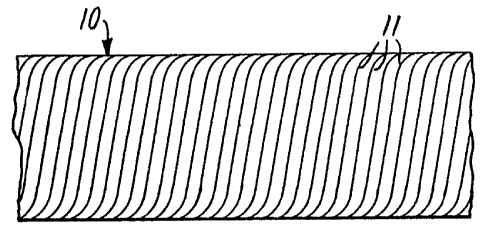
structure which is inherent to the process. FIG. 1
illustrates a typical air-laid web 10 formed on Rando
WebberSM air-laying equipment. The fibers are laid down in
shingles 11 which normally are inclined at an angle of
between about 10 to 40 to the faces of the web. Some of
the most important factors influencing the angle of the
shingle include the length of the fiber used to form the
web, the type of collector used in the machine, and the
basis weight of the web.
Generally, longer fibers produce a web having a
larger shingle angle than do shorter fibers. A web having a
lower basis we$ght generally has a lower shingle angle than
a simllar web at a higher basis weight. The collector is
generally an inclined wire or a perforated metal cylinder,
the cylinder being preferred. Smaller diameter cylinders
produce webs having a larger shingle angle than large
diameter cylinders produce. The length of the web contact
zone on the collector, i.e., the distance in which the web
is in contact with the collector cylinder also affects the
shing}e angle with a longer distance creating a lower
shingle angle.
The shingled structure of the web can be used to
advantage in creating a web structure that has superior
thermal weight efficiency to down and that also has the
resiliency of down. By reconfiguring the shingle structure
from its original shallow angle of 10 to 40, as shown in
FIG. 1, to an angle of at least about 50, preferably at
-10- ~2~4'~'1
least about 60; and most preferably approaching goa, i.e.,
80-90, as illustrated in FIG. 2, the web becomes a
substantially columnar structure which is capable of
enduring compressive challenges and providing lower bulk
densities than those associated with the starting web. The
reconfigured web structure capitalizes on the natural
resilience of the fibers by orienting them substantially
lengthwise to the compressive forces exerted on the web.
Several methods are presentl~ available to effect
the reconfiguration of the shingled structure in an air laid
web, including, but not limited to, running two conveyer
belts at differing speeds so as to move one face of the web
at a faster down-web speed than the other, a "lift" process,
a "sag" process and an optional "combing" or "brushing" step
which can be added to either the "lift" or "sag" processes
to cause an additional reconfiguring, or repositioning, of
the fibers in the web.
In the "lift" process, illustrated in Figure 3,
air-laid web 31, which has the above-described shingle
structure, passes from a first transport means 32, such as a
conveyer belt, to a second transport means 33, such as a
second conveyer belt, which is positioned slighbly higher
than first transport means 32. ~y ~lifting" the web in this
manner, the bottom surface of web 34 is shifted forward
relative to the top surface of the web and the shingle
structure 35 is concurrently moved toward a more vertical
fiber configuration wherein the shingles of the web become
more perpendicular to the surface. This process may require
several "lifts" to achieve the desired amount of
reconfiguration. In FIG. 3, a "brush" 36, which consists of
a rectangular piece of 40-pound card stock 37 which is
hinged at its top edge 38 so that the bottom edge 39 lightly
brushes the top of the web is utilized to introduce further
reconfiguration of the shingle structure.
In the "sag" process illustrated in FIG. 4,
air-laid web 41, which has the above-described shingle
-11- 129S4 ~1
structure, is allowed to drop from a first transport means
42, such as a conveyer belt, in an unsupported fashion, and
then to develop a "sag" 43 before being picked up by a
second transport means 44, such as a second conveyer belt.
The "sag" causes the fibrous shingles of the web to move
relative to one another and to the faces of the web such
that a more vertical fiber structure is produced in the web
whereby the shingles become more perpendicular to the
surface. The addition of a comb 45, such as a lS dent comb,
which lightly contacts the top surface of the web after the
"sag" can be used to introduce further reconfiguration of
the fibers, i.e., to cause the fibers to be even more
closely vertical to the web face. This "sag" process is
generally more efficient than the "lift" process, but may be
less controllable, and, therefore, ~he "lift" process is
generally preferred.
While each of these processes results in a
reconfiguration of the shingle structure in the central
portion of the web, the comparatively non-directional,
hlghly entangled fiber structure on the top and bottom faces
of the batt which results from the air laying of the web is
not significantly altered.
After the web has been reconfigured, the web is
heated sufficiently to effect interfiber bonding by the
bondlng flbers with other bonding fibers and with structural
fibers to stab~lize the reconfigured web to form the
nonwoven thermal insulating batt of the invention. The
temperature of the oven in which the web is heated is
preferably about 40 to 70C above the temperature at which
the adhesive portion of the bondable fiber melts.
The nonwoven thermal insulating batts of the
present invention exhibit outstanding thermal insulating
properties about comparable to or exceeding those of natural
and synthetic down products. While the reasons for this
outstanding performance are not fully understood at this
time, it is speculated that the columnar structure of the
-12- lZ~4~1
reconfigured web contributes not only to the resilience of
the web but also to reducing heat losses from radiation. It
is suspected that this possible contribution of the columnar
structure to reducing heat loss by radiation may be due to
the fact that fibers radiate heat outward from their surface
and with perpendicular fibers radiation is predominantly
within the plane of the batt rather than outward from the
batt.
While the principal application for the batts of
the pres~nt invention lies in the area of light weight
thermal insulation materials, they are also useful for a
number of other areas, including acoustical insulation and
cushioning applications where the work to compress,
resilience, and loft retaining properties of the batts can
be advantageously utilized.
The following examples further illustrate this
invention, but the particular materials and amounts thereof
in these examples, as well as other conditions and details,
should not be construed to unduly limit this invention, In
the examples, all parts and percentages are by weight unless
otherwise specified.
In the examples, thérmal resistance of the batts
was evaluated with the heat flow upward, according to
ASTM-D-1518-64, to determine the combined heat loss due to
convection, conductlon and radiation mechanisms. Heat losses
due to the radiation mechanism were determined using a
Rapid-~ unit (Dynatech R/D Company of Cambridge, MA) with
the heat flow downwards.
Examples 1-6
Structural fibers (SF) and bonding fibers (BF)
were opened and mixed using type B, Rando WebberTM
air-laying equipment with the amounts and types of fibers as
follows:
Example 1: 60~ SF (FortrelTM Type 510, a polyethylene
terephthalate fiber, 1.2 denier, 3.8 cm long,
available from Celanese Corp.) and
-13_
40% ~F (MeltyTM Type 4080, a bonding core/sheath
fiber, 2 denier, 5.1 cm long, available from
Unitika Corp.);
Example 2: 60% SF (FortrelTM Type 417, a polyethylene
terephthalate fiber, 1.5 denier, 3.8 cm long,
available from Celanese Corp.) and
40% BF (MeltySM Type 4080, a bonding core/sheath
fiber, 4 denier, 5.1 cm long, available from
Unitika Corp.);
Example 3: 60% SF (FortrelTM Type 510) and
40% BF (MeltyTM Type 4080, 4 denier, 5.1 cm
long);
Example 4: 45% SF ~FortrelTM Type 510),
10% SF (KodelTM Type 431, a polyethylene
terephthalate fiber; 6 denier, 3.8 cm long,
available from Eastman Chemical Product~, Inc.),
and
45% BF (MeltyTM Type 4080, 2 denier, 5.1 cm
long); and
Example 5: 65% SF (FortrelTM Type 510) and
35% BF (MeltyTM Type 4080, 4 denier, 5.1 cm
long); and
Example 6: 60% SF (Fortrel TM Type 510) and
40~ BF (Melty TM Type 4080, 2 denier, 5.1 cm
long).
~ .
:;
~ ::
-14-
The opened and mixed fiber blends were then
air-laid using type B Rando WebberTM air-laying equipment to
produce air-laid webs. In Examples 1-4, the web was
reconfigured by allowing the web to sag to a depth of about
7 cm in an unsupported manner between a first conveyer, a
slot conveyer, and a second conveyer, a galvanized wire
screen conveyer, having a 10 cm linear gap between
conveyers, the second conveyer being about 30 cm above the
first conveyer, and the first conveyer travelling at a rate
of 2.4 m/min and the second conveyer traveling at a rate of
2.7 m/min. In Examples 5 and 6, the web was reconfigured by
lifting the web from a first conveyer to a second conveyer,
the second conveyer being 0 cm linearly distant and 30 cm
above the first conveyer, and both conveyers traveling at a
rate of 2.7 m/min. In Examples 1, 5, and 6, the web was
further reconfigured by brushing the top of the web with a
hinged panel of 18 kg/ream stiff card stock paper. In
Example 2, the web was further reconfigured by combing the
top of the web with a 15-dent textile loom comb. Each
reconfigured web was then passed through an air circulating
oven at the temperature and dwell time set forth in Table I
to achieve a stabilized batt having the basis weight set
forth in Table I. The thickness of each batt was determined
with a 13.8 Pa force on the face of the batt and the
reconfigured shingle angle was measured. The thermal
insulating value for each batt was measured and the weight
efficiency and thermal insulating value per cm thickness
were determined. The results are set forth in Table I.
12~S~
-15-
Table I
Example 1 2 3 4 5 6
Oven temp. 160 155 155 155 160 160
( C)
Dwell time 120 120 150 120 135 120
tsec)
Basis wt. 67 70 90 149 142 68
~ g/m2 )
Thickness (cm) 2.5 2.0 2.6 4.5 3.8 2.8
Bulk de~sity 0.0027 0.0035 0.0035 0.0033 0.0037 0.0024
(g/cm )
Reconfigured 60-70 60-70 60-70 80-90 70-80 60-70
shingle
angle ()
Thermal 2.12 1.91 2.42 3.56 2.78 2.08
resistance
(clo)
Weight 31.6 27.3 26.9 23.9 19.6 30.6
efficien2cy
(clo/g/m
x looo)
Clo/cm thick- 0.85 0.95 0.92 0.79 0.73 0.75
ness
As can be seen from the data in Table I, the
thermal insulating batts of the invention have excellent
thermal resistance. The batts of Examples 1 and 6 possess
exceptionally superior thermal weight efficiencies at low
bulk densities.
Example 7 and Comparative Examples Cl-C3
Samples of QuallofilSM, available from DuPont,
Inc. (Comparative Example Cl), Hollofil~M 808, available
from DuPont, Inc. (Comparative Example C2), an unbranded
commercially available, resin bonded thermal insulation
material, (Example C3), and a sample of batt prepared as in
Example 1, except having a basis weight of 75 g/m2, (Example
-16- 129S~l
7) were tested for basis weight, thickness, clo value, and
weight efficiency. Then a sample of each batt, 28 cm x 56
cm was placed between two sheets of woven nylon fabric, 28
cm x 56 cm, and the perimeter edges were sewn together to
form a panel to simulate garment construction. Each panel
was used as a seat cushion, being subjected to repeated
compressions, twisting, and sideways forces, for eight days.
Each panel was then fluffed for 45 minutes in a clothes
dryer on air fluff cycle, the batt measured for thickness,
clo value, and weight efficiency, then laundered in a
MaytagSM home washer using 41 minutes continuous agitation
with warm water, and a gentle cycle followed by normal rinse
and spin, and dried in a Whirlpool~M home dryer at medium
heat on permanent press cycle after each laundering. The
thickness, clo value, and weight efficiency of each batt
were again measured. All test results are set forth in
Table II.
Table II
Example 7 C1 C2 C3
Basls welght (g/m2175 145 116 157
Bulk density (q/cm31
Initial 0.00240.00440.0054 0.0052
Fluffed 0.00510.00550.0056 0.0067
Laundered 0.00450.00550.0059 0.0069
Thickness (cm)
Initial 3.2 3.3 2.2 3.0
Fluffed 1.5 2.7 2.1 2.4
Laundered 1.7 2.7 2.0 2.3
Thermalir;sistan 2.6 3.3 2.8 2.8
Fluffed 1.9 2.8 2.2 2.5
Laundered 2.0 2.4 1.9 2.3
Weight e2fficiency
(clo/q/m x 1000)
Initial 34.9 22.4 23.7 17.5
Fluffed 25.5 19.3 19.2 15.7
Laundered 26.4 16.7 16.2 14.3
-17- 1~5~ ~1
As can be seen from the data in Table II, the batt
of Example 7 had greater thermal weight efficiency initially
and after compression, fluffing, and laundering than the
comparative thermal insulating materials.
s
Example 8 and Comparative Examples 4-9
For Example 8, a batt was prepared as in Example
1, except that the basis weight was 70 g/m2. The thermal
conductivity for this batt was determined using a Rapid-K
unit with the heat flow downward and series of reduced
spacing6 between the hot and cold plates to increase bulk
density. ~inear regression analysis of the data using bulk
density (kg/m3) and the product of the bulk density and
thermal conductivity (W/mK) provided an equation where the
radiation parameter is given by the intercept of the
equation at zero bulk density. Similar determinations were
also determined for two commercially available materials:
QuallofilSM~ 145 g/m2, available from DuPont, Inc., and a
157 g/m2 commercially available resin bonded thermal
in6ulating material. The results are set forth in Table III
together with radiation parameters calculated from published
data for the other listed thermal ihsulating materials.
The radiation parameter is particularly useful in
determining the relative thermal emissivity of thermal
insulating materials. Radiation heat losses become a more
important factor in very low density materials where the
fiber mass is small and heat loss due to thermal
conductivity is minimized. The lower the radiation
parameter, the lower the heat loss due to thermal radiation.
.... ......
-18~
Table III
Thermal insulating Radiation
Example material parameter
8 Batt of invention 114
C4 Quallofil~M 184
C5 Unbranded material 290
C6 Synthetic down
(U.S. Patent No. 4,588,635) 137
10 C7 PolarguardTM 233
C8 HollofilTM II 295
C9 Down 137
As can be seen from the data in Table III, the
thermal insulating batt of Example 8 yielded a lower
radiation parameter than any of the comparative thermal
insulating materials including down.
Example 9 and Comparative Examples C10-Cll
Thermal insulating weight efficiency
determinations were made on a batt prepared as in Example 2
(Example 9); QuallofilSM thermal insulating material having
a basis weight of 145 g/m2 and a thickness of 3.3 cm
(Comparative Example C10), and unbranded commercially
available thermal insulating material having a basis weight
of 157 g/m2 and a thickness of 3.1 cm (Comparative Example
11). Samples of each material were subjected to forces of
compression and tested for thermal efficiency under
compression. The results of these tests are shown in FIG.
5, where the solid line (A) represents the weight efficiency
of the batt of Example 9 and the dotted line (B) and broken
line (C) represent the weight efficiencies of the thermal
insulating materials of Comparative Examples C10 and Cll,
respectively.
.. . .
-19- ~29~
As can be seen from FIG. 5, the thermal insulating
batt of Example 9 had better thermal weight efficiency at
various thicknèss fractions than either the Quallofil TM or
unbranded thermal insulating materials.