Note: Descriptions are shown in the official language in which they were submitted.
1 BACKGROUND OF THE INVENTION
FIELD OF THE INVENTION
The present invention relates to an ultrasonic
surgical apparatus for crushing, sucking, and removing
undesirable substances existing in the body, such as ulcerous
tissue, thrombuses, calcification aggregates, etc. by means
of ultrasonic vlbrations of a flexible ultrasonic probe.
. DESCRIPTION OF THE PRIOR ART - -
As conventional methods of removing thrombuses, -
the following methods are known: one in which a catherteris inserted into a thrombus portion and the thrombus is
dissolved by injecting thereinto a thrombolytic agent such
as streptokinase (e.g., Japanese Patent Unexamined
Publication No. 173065/1982), one in which a catherter is
withdrawn while maintaining the balloon of a balloon
catherter in an expanded state, and, at the same time, a
~ ~ thrombus is removed (e.g., Japanese Patent Examined
; ~ Publication No. 16472/lg74), and one in which a thrombus
portion is clamped by two expanded balloons, the thrombus
is softened by injecting a thrombolytic agent thereinto, a
catherter is then withdrawn, and, at the same time, the
thrombus is removed (e.g., Published Japanese Translation
:
of PCT Appln., Publication No. 501983/1983).
However, even if the thrombolytic agent is injected
locally after the insertion of the catherter, there is a
~'
i7
1 drawback in that the thrombolytic agent f lows into normal
terminal blood vessels and the like, thereby entailing the
risk of hemorrhage in the terminal blood vessels and the
like. Meanwhile, in the case where the catherter is
withdrawn by maintaining the balloon of the balloon
catherter in a expanded state and, at the same time, the
thrombus is removed from the body, there is the risk of
causing damage to the inner wall of a blood vessel since a
safety measure against a tensile stress applied to the inner
: 10 wall of the blood vessel has not been taken. In the case
where a catherter provided with two balloons is used as a
similar method of removing a thrombus, when a thrombus 27
is clamped by two balloons 31, 32, as shown in Fig. 7, the
balloon 32 located closer to the tip of a catherter 30 needs
to be inserted from a position 34 in front of a thrombus 27
up to an innermost position 35 which is farther from the
thrombus 27, so that there is the danger of causing the
balloon 32 to push the thrombus 27 in the inserting direc-
tion 33, thereby moving the thrombus 27 to another part, such
as a terminal blood vessel.
Furthermore, as a method of mechanically removing
a thrombus, there is one in which a drill bit is provided to
the tip of a bar-like member, the drill bit is made to
rotate by rotating the bar-like member, and the thrombus is
crushed by the rotating drill bit. With this method,
however, a torsional stress is applied to the inner wall of
the blood vessel, so that there is a drawback in that the
blsod vessel may be cut off by said stress, and adjustment
-- 2
1 of the number of revolutions and the like is hence made
difficult.
Recently, as a surgical apparatus using ultrasonic,
an apparatus is known in which an ultrasonic probe is
connected to a source of ultrasonic vibration, tissue, a
calcification aggregate, thrombus, or the like is crushed
by mechanical vibrations of an ultrasonic frequency generated
at the tip of the ultrasonic probe, and the crushed tissue,
calcification aggregate, thrombus, or the like is removed
through an inner hole provided in the ultrasonic probe
(e.g., Japanese Patent Examined Publication Nos. 5139/1985
and 21989/1974). With such an apparatus, however, since
the ultrasonic probe having a wor~ing portion which
mechanically vibrates at an ultrasonic frequency is not
flexible, there is a drawback in that it is diffucult to
insert the ultrasonic probe into a tubular tissue inside
the body.
SUMMARY OF THE INVENTION
Accordingly, an object of the present invention
is to provide an ultrasonic surgical apparatus which is
capable of allowing a flexible ultrasonic probe to be
. inserted directly into the affected part, crushing an unde-
~ sirable subs-tance in the body such as a thrombus, a
calcification aggregate, or the like by means of mechanical
vibrations of an ultrasonic fr~quency, and removing the same
by suction without affecting the normal surrounding tissue,
thereby overcoming the drawbacks of the prior art, including
: ~ - 3 -
1 the risk of hemorrhage caused by a thrombolytic agent, the
risk of causing damage to a blood vessel owing -to a tensile
or torsional stress applied to the inner wall of the blood
vessel by the use of a balloon catherter, and the drawback
o movement of the thrombus at the time of insertion of the
balloon catherter.
Another object of the pxesent invention is to
provide an ultrasonic surgical apparatus which is capable o
crushing and removlng a thrombus, a calcification aggre-
gate, or the like in the tubular tissue of such as a bentblood vessel, for which an operation has been difficult
using a conventional ultrasonic surgical apparatus.
To this end, the present invention provides an
ultrasonic surgical apparatus having an ultrasonic vibration
source for generating ultrasonic vibrations, an oscillator
for supplyi.ng high-frequency electric energy lo the ultra-
sonic vibration source, a horn connected to t~e ultrasonic
vibration source and adapted to transmit and amplify
mechanical vibrations of an ultrasonic frequency, and a
suction device for sucking and removing an undesirable
substance from an operated part, comprising an ultrasonic
probe which is constituted by a flexible linear transmitting
member, is secured at one end thereof to a tip of the horn
and has at the other end thereof a working portion for
~5 effecting mechanical vibration of an ultrasonic frequency,
~; a horn cover at least a portion of which is made of a
flexible material, at least one inner tube, at least one
branch tube communicating with the inner tube, and a
- 4 -
67
l flexible tube connected to the horn cover, wherein -the
ultrasonic probe is installed in the inner hole, and the
suction device is connected to the branch tube.
BRIEF DESCRIP~ION OF THE DRAWINGS
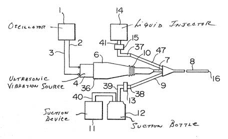
Fig. l is a diagram schematically illustrating the
overall arrangement of an ultrasonic surgical apparatus in
accordance with an embodimen~ of the present invention;
Fig. 2 is an enlarged diagram of a handpiece
portion and illustrates the arrangement of the interior of
a horn cover;
Figs. 3(a~ and 3(b) are enlarged diagrams of a
bellows portion, in which Fig. 3(a~ shows a state in which
the bellows portion is extendedr while Fig. 3(b) shows a
state in which the bellows portion is shrunk;
Fig. 4 is a diagram illustrating another example
of the configuration of the handpiece;
Figs. 5(a) and 5(b) are diagrams explaining an
example of using the apparatus in accordance with the presen~
invention;
Figs. 6(a) and 6(b) are diagrams illustrating the
cross-sectional structure of a flexible tube in accordance
with the embodiments of the present invention; and
Fig. 7 is a diagram illustrating a conventional
method.
:
DESCRIPTION OF THE PREFERRED EMBODIMENTS
Referring now to the accompanying drawings, a
- 5 -
:"
~L2~
1 detailed description will be made of the present invention.
Fig. 1 is a diagram schematically illustrating the overall
arrangement of an ultrasonic surgical apparatus in accord-
ance with an embodiment of the present invention. As shown
in Fig. 1, the apparatus is comprised of the following four
sections: a section for generating mechanical vibrations of
an ultrasonic frequency which is constituted by an oscil-
lator 1 and a handpiece 36, a suction section constituted by
a suction device 11 and a suction bottle 12, a liquid
injecting section constituted by a liquid injector 14, and
a catherter section constituted by a flexible tube 8,
branch tubes 7, 9, and 47.
High-frequency electric energy is supplied from
the oscillator 1 to the handpiece 36 via cables 2, 3. As
shown in Fig. 2, the handpiece 36 is consti-tuted by an
ultrasonic vibration source 4, a horn 5, a horn cover 6, and
an ultrasonic probe 17. The high-frequency electric energy
is supplied to the ultrasonic vibration source 4, which in
turn generates mechanical vibrations af an ultrasonic
frequency and transmits the same to the horn 5. The
mechanical vibrations are enlarged by the horn 5 and are
transmitted to the ultrasonic probe 17.
; The oscillator 1 has an oscillation circuit which
is capable of supplving high-frequency electric energy
corresponding to fluctuations in the state of the mechanical
load of the horn 5 and the ultrasonic probe 17. Although
15 - 40 kHz is suitable as an osclllation frequency, 20 - 30
kHz is suitable in view of the mechanical vibrations of the
- 6 -
1 ultrasonic frequency o~ the ultraso~ic probe 17 and the
crushing capability thereof.
Although the connection between the ultrasonic
vibration source 4 and the horn S is effected by a screwing
method, said connection should not be restricted to that
type. The ultrasonic vibration source 4 should not be
particularly restricted insofar as it is capable of
converting high-frequency electric energy of the magneto-
striction type, the electrostatiction type, or the li~e
into mechanical vibrations. As for the material of the horn
5, a metallic material which is capable of transmitting and
enlarging the mechanical vibrations of an ultrasonic
frequency and has a fatigue strength sufficient to withstand
the mechanical vibrations, and stainless steel, duralumin,
a titanium alloy, or the like is preferable.
In addition, as for a method of connecting the
horn 5 and the ultrasonic probe 17, the screwing method,
welding, or the like is suitable. The ultrasonic probe 17
is constituted by a fixing member 43 and a flexible linear
transmitting member 44, and, as for a method of connecting
the fixing member 43 and the linear transmitting member
44, welding, adhesion, or the like is suitable. The
materials of the fixing member 43 and the linear transmitting
member are not particularly restricted if they are capable
of transmitting the mechanical vibrations of an ultrasonic
frequency and have a fatigue strength sufficient to
withstand the mechanical vibrations. However, said materials
should preferably be such that an X-ray cannot be transmitted
7 -
.
1 therethrough, and a metallic material, lncludlng stalnless
steel, duralumin, and a tltanlum alloy, or a composite
material such as carbon flber-reinforced plastlcs is
preferable. The horn cover 6 ls provlded around the horn
5 and the flexible ultrasonic probe 17. O~e end of the horn
cover 6 is connected to the ultrasonlc vibration source 4
by an appropriate method, whlle the other end thereof is
connected to the branch tube 7 by means of an adhesive so
as to retain airtightness. However, the method of this
connection should not be restricted to the same. The
interior of the horn cover 6 is divided into partitioned
chambers 23, 45 by means of a rubber O-ring 22, the rubber
O-ring 22 being located at a knot portion where the longi-
tudinal (46) amplitude of the mechanical vibrations of the
horn 5 is the mlnimum so as to shield the passage of the
liquid. In addition, by providing a portion of the horn
cover 6 with a bellows portion 10 formed of a flexible
material, it is possible to move the branch tube 7 back and
forth by virtue of the longitudinal (46) expansion and
shrinkage of the bellows portion (10).
The ultrasonic probe 17 is installed through the
branch tube 7 and inside ~he inner hole of the flexible
tube 8 shown in Fig. 1. As shown in Fig. 3(a), the tip of
the ultrasonic probe 17 has such a dimension that, when the
2S bellows portion 10 is in an extended state, said tip will
not protrude from the tip 16 of the flexible tube 8.
Consequently, when the flexible tube 8 is inserted into the
body, the tip of the ultrasonic probe 17 is located in the
- 8 -
1 inner hole of the flexible tube 8, thereby making it
possible to prevent the occurrence OL damage to a blood
vessel or the like caused by the tip of the ultrasonic
probe 17.
As shown in Fig. 1, the suction device 11 is com-
municated with the lnner hole of the flexible tube 8 via
the branch pipe 9, a changeover valve 13, the suction
bottle 12, and tubes 38, 39, and 40. The liquid injector
14 is communicated with the inner hole of the flexible tube
8 via the branch tube 47, a pipe 37, a changeover valve 15,
and a tube 41. As for a method of arranging the branch
tubes 9 and 47, although Fig. 4 illustrates an example in
which the branch tubes 9 and 47 are secured to the horn
cover 6 by means of an appropriate adhesive, the arrange-
ment may be such as to provide a configuration that
facilitates the use of the apparatus by the operator and
should not be restricted to the illustrated example.
As for the method of using this apparatus, the
: partitioned chamber 23 and the inner holes 42, 20 are
filled with a li~uid which is not harmful to the bodily
tissue, such as physiological saline, by an appropriate
means so as to facilitate slippage of the linear transmit-
ting member 44 installsd inside the branch tube and the
flexible tube 8. For instance, a passage leading to the
partitioned chamber 23 is provided on the side of the horn
~: cover 6, a liquid such as physiological saline is injected
into the partitioned chamber 23 and the inner hole 42, 20
through that passage, and the passage is then closed. Also,
_ g _
",
i7
1 the inner suction hole 19 of the flexible tube 8 communi-
cating with the suction device 11 and the inner hole of the
branch tube 9 are filled with a liquid such as physiological
saline by means of the operation of the suction device 11
and the changeover valve 13. With respect to the liquid
injector as well, the branch tube 47 and the inner hole 20
are similarly filled with a liquid such as physiological
saline.
Next, while confirming the position of the tip of
the linear transmitting member 44 while projecting X-rays,
the flexible tube 8 is inserted into the body and is insert-
ed up to a portion to be operated on, 2 .g., a thrombus
portion. For example, as shown in Fig. 5(a), a balloon 26
is provided in the vicinity of the tip 16 of the flexible
tube 8. The balloon 26 is temporarily expanded using an
inner hole (This inner hole is not illustrated, but when the
balloon is used the inner hole similar to an inner hole 18
is additionally provided.) provided in the flexible tube
8 ~or the balloon to such an extent that an adverse effect
will not be exerted on the flow of blood 24, so as to
position ana secure the tip 16 since the flexible tube 8
oscillates owing to the flow of the blood inside a blood
vessel 25. At this time, the mutual relationships between
the flexible tube 8 and the linear transmitting member 44
are in the state shown in Fig. 3(a). Subsequently, when
the bellows portion 10 is shrun~ in the direction of the
arrow 28 while holding a part of the horn cover 6 on the
side of the branch tube 7 in relation to the bellows
-- 10 --
1 portion 10, a working portion 21 of the ultrasonic probe 17
can be made -to project from the tip 16 of the flexible tube
8, as shown in Fig. 3(b). Hence, the balloon 26 is shrunk
after adjusting the position of the working portion 21 in
relation to the thrombus 27. Then, as shown in Fig. 5(b),
the ultrasonic probe 17 is mechanically vibrated at an
ultrasonic frequency, the working portion 21 is brought
into contact with the thrombus 27 to crush the thrombus 27.
The small crushed pieces of the thrombus are sucked by the
suction device ll from the inner suction hole l9 shown in
Fig. 6(a) and are removed out of the body. In addition,
when the position of the thrombus 27 is unclear, a contrast
medium or the like is injected from the liquid-injecting
inner hole 18 shown in Fig. 6(a) by means of the liquid
injec-tor 14, and the above-described operation is carried
out while confirming the position of the thrombus 27.
The material of the flexible tube 8 may be the one
which is normally used for a medical catherter, such as
soft vinyl chloride resin. On the other hand, the materials
of the branch tubes 7, 9, and 47 are not particularly
restxicted, but one which is capable of adhering with the
flexible tube 8 is preferable. The inner hole and outer
periphery of the flexible tube 8 and the inner holes of
~ the branch tubes 7, 9, 47 are coated with an antithrombotic
substance. As for this antithrombotic substance, poly-
urethane, hydrogel, heparinated polymer, urokinase~coupled
polymer, or the like is preferable, but the substance is
not particularly restricted.
1 Furthermore, the number of the inner holes of the
flexible tube 8 is no-t particularly restricted. For
instance~ in a case where one inner hole 20 is provided,
as shown in Fig. ~(b), the inner hole 20 haviny the ultra-
sonic probe 17 can be used by being changed over by means
of a changeover valve such as to communicate with the
suction device 11 and the li~uid injector 14.
As for the working portion 21 at the tip of the
ultrasonic probe 17, an acute-angled portion thereof has
been removed so as to prevent damage to the inner wall of a
blood vessel and the like. Although the configuration of
an end surface thereof is not particularly restricted, it
is preferable to make the same oblique-angled or arcuate.
Although a detailed description has been made with
respect to a case where the apparatus in accordance with
the present invention is used for removal of a thrombus
in a blood vessel as one embodiment thereof, the usage of
the present apparatus should not be restricted to such, and
it goes without saying that the apparatus can be suitably
used e~tensively for crushing or removing other undesirable
substances in the body.
~ s described above, in accordance with the present
invention, it is possible to insert an ultrasonic probe
directly into the affected part where an undesirable
substance, such as a thrombus, calcification aggregate,
ulcer, or the like occuring in a narrow tubular tissue such
as a bent blood vessel is present and crush the unde-
sirable substance by means of mechanical vibrations of an
~ 12 -
~2~
1 ultrasonic frequency and immediately remove the same out of
the body without adversely affec-ting the normal surrounding
tissue. At the same time, an incised portion at the body
surface can be made only slightly larger than the diameter
of a flexible tube enveloping an ultrasonic probe. Hence,
an operation which gives a very low level of stress to the
patient is can be carried out within a short period of time.
Consequentlyr the burden on the patient after the operation
can be alleviated substantially, so that the apparatus of
the present invention can be suitably used as an ultrasonic
surgical apparatus.