Note: Descriptions are shown in the official language in which they were submitted.
2S~
BACJGROUND OF ~HE INVE.~rION
_ield of_ tke_ Inierlt on
The present invention relates to an
osteosynthetic implant for the fi~ation and/or
support of flat and tubular bone fradments,
particularly in chlldren.
Description of the Prior Art
Osteosynthetic implantation is
currently practiced primarily in adults. Only in
a ~ery limited number of cases, such as, for
e~ample, in multiple fractures, is osteosynthetic
implantation practiced T~7ith children during their
growth years. The use of synthetic implants in
children may result, it is l;not~n, in growth
disturballces which require corresponding surgical
corrections. Preliminary e~periments with
osteosynthetic connecting elements t~ere
performed, although not specifically with
reference to pediatric surgery, using screws made
f`rom reabsorbable material. The results of these
experiments were not encouraging, particularly as
re~gards implantat1on o~f the osteosynthetic
connecting elements. The range of application
was limited, but the screws generally did not
: : :: :: : :
withstand stresse~s produced during the process of
implantation. The screw heads eenera1ly broke
because the reabsorbable materlal had
nsufficient strength. Also, the problem of
; f1~ation t~as not solved for those cases in which
: :: :
:: ::: : :: 3
F-154 2
~29~
the irldividl1al bone fragmen-ts had to be supported
b~ additional elements sueh as plates or cerclage
Ull its.
Wor~ proceeded from eonsiderations and
e~periences gained from osteosynthetic
implantation in adults. In the use of metal
i~lplants, a level of microstability must be
attained, that is to sa.y, a level of stability
which permits only the srnallest mo-enlents between
the fra~Jments. Microstable connections permit
stresses of appro~imately 60-80 Icp over the area
of the fractllre, Wit}lOUt perceptible movements
be;llg noted.
rhe consi.derable elasticity of bones of
children al~d adolescents in -t.heir grc)~th years
perlnits, however, a l.evel of macrostability.
~acrostable eonnections, subjected to a stress of
10-20 kp o~er the area of the fracture, still
perlnit slight, pereeptible movements. The
fracture is tbereby stable as to support and
movement. A microstable osteos~nthetie
implantation such as is achievable, for e.~ample,
in adult surgery, is not interlded for c.hildren
and adolescents.
This Icnowledge is conseiously utilized
:~ by the inventor to provide a new osteosynthetie
implant ~hich is suitable for use in pediatrie
surgery.
'
4 3
~L~96~S6
SU~I~IAR~' OF THE INVENTION
.
It is an object of the present
in~ention to proYide a synthetic implant for
pediatric surgery which provides osteosynthetic
contacts causing no growth disturbances, or onl~-
very slight levels of growth disturbances,
The osteosynthetic implant
described herein comprlses a band of
reabsorbable material which i~s attachable to bone
fragments b~ means of connecting elements of
reabsorbable material penetrating the band and
the bone fragments. The use of connecting
ele~ents colllprising reabsorbable material with
the bands, l~hich function lii~e tension belts,
enables osteosynthetic implantation even in
children during their growth ye,trs without
cau~ing growth disturbances, and ach.ieves the
necessary macrostability.
In fractures of hollow cylindrical
bones, hollow screws having a head, a central
bore with a regular cross-sectional
configuration, such as a cYlindrical bore with
e~tended portions directed radially -out~ardly in
a cruoiform~fash1on, and an a~ial penetratlng
aperture provided at the tip of the screw are
preferred. S~ch screws require the use:of a
special tool for~ implantation, by means of which
the distribution of rorce during insertion of the
scret~s is even over approximately the entire
.
F-1~4 4
~L2~ 5~i
length of the screw, so that the screw does not
break during insertion.
The e~tended portions of the
cylindrical bore rna~- be constructed as channel
groo~-es to avoid any outwardly directed force to
prevent the screw from breaking.
The penetration of the screws and the
reabsorption of the reabsorbable material of the
screws and bands is i.mpro~ed when the hollow
screws are provided with radially penetrating
hol.es.
The tool which is disclosed for use
during osteosynthetic implant,ation using the
ho]low screws described above comprises a
screwdriver havi.rl~ an ext.ernal contour
corresponding ~o the cross-sectional
configuration of the internal bore of the scre~i,
and an a.~ial centering pin. The centering pin
serves to guide the screw in an allgning ~lanner
with respect to the bore hole in the bone.
In order, on the one hand, to penetrate
the bands, and, on the other hand, to center the
screw in the bore of the bone fragment, it is
:
preferred that:the centering pin is supported in
an axially displaceable manner against spring
pressure in the screwdriver.
F-154 5
~g~2S~
In accordance with the invention, there is provided an
osteosynthetic implan~ for the fixation and support of flat and
tuhular bone fragments comprising: at least one connecting band
attachable to join said bone fragments by means of at least two
connecting elements penetrating said connecting band and said
bone fragments, said connecting band and said connecting
elements both comprising biocompatible material which is
reabsorbable.
Embodiments of the invention will now be described
with reference to the accompanying drawings in which;
Fig. 1 shows an example of craniofacial application of
the osteosynthetic implant embodying the present invention;
Fig. 2 shows a top view of a band with a connecting
element comprising reabsorbable material;
Figs. 3a and 3b show a perspective view of a tamping
liner and a tamping counterpiece in cross section;
Fig. 4 shows a cross-sectional view illustrating the
use of the osteosynthetic implant with hollow screws for a
hollow cylindrical bone fracture;
Fig. Sa shows a side view of the hollow screw used in
the osteosynthetic implant shown in Fig. 4;
Fig. 5b shows an end view of the head of the hollow
screw shown in Fig. Sa;
Fig. 5c shows an end view of ~he tip of the hollow
screw shown in Fig. 5a;
Fig. 6 shows a perspective view of a screwdriver for
use in implanting the hollow screw shown in Fig. 5a;
' ~ 6
~2~2S~
Eig. 7 shot;s an enlarged cross-
sectional ~-iew of the terminal end of the
screwdri~er in the shaft of a hollot~ screw; and
Fig. 8 shows a graphical representation
of the strength of the connection bett~-een the
bone fragments in relation to the healing time.
DESCRIPTION OF PREFERRED EMBODIMENTS
The osteosynthetic-implant embodying
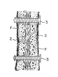
the present i:nvention utilizes:
connecting elements and bands, the bands ser~-ing
as tension belts which evenly transfer forces
from one ?.~one fragment to the other to fi~ both
fragnlents in place. The connecting elements
~enetrate the band or bands and the corresponding
bone fraglnellts. The borle fragments are
designated by reference letter (F) in the
fig~lres. Connecting elements (1), which, in
practice, are only a few millimeters in diameter,
are shown in the diagram as points. The bands
are designated by reference numeral (2). The
distanee between the bone fragments is, for the
sake of claritv, depicted on a larger scale than
life-size.
An enlarged ~ieu of one embodiment of
~the osteosynthetic implant 1S shown in Fig. 2.
Band (2) is knit or wo~en from filaments of
reabsorbable biocompatible materials. The mesh
uidth, the f1lament distance, and the shape are
selected so that the tissue or wea~e is easily
:
~-154 7
i2~
penetrated by the connecting elements It i5
essential that the elastic defornlation of the
band in the ~ongitudinal direction be relati~~ely
slight. Longitudinal elastic deformation is
influenced b~ the corresponding filament shape
and ~.-eave. As Fig. 2 shows, filaments (21) are
preferably only displaced in the area where
connecting elements pene1rate the band (2).
Depending upon the type of bone
fragn1ents to be cGnnected, different connecting
elements may be used. Connecting elements may be
fabricated fro1n l;nown materials, such as, for
e~ample, polygluconate, polylactate, and the
like, 1~hich are biodegradable and biocompatible.
In Figs. 3a and 3b, connectin~ elements
suitable for connecting flat bone fragments are
shown in a perspective, cross-sectional view. A
tamping liner is designated by reference numeral
(10), comprising tubular part (ll) with an
ann~ular collar unit (12) at one end. According
to a preferred embodiment, the wall thichness of
annular collar unit (12) may be, for e~;ample,
about 0.5 mm~ with a total length of
~ppro~;mately 2 mm. The diameter of collar unit
(12) may be appr~ximately 5 mm, while the
internal diameter of the tubular part (ll) may be
appro~imately 2 mm. Tamping counterpiece (13) is
graduated in diameter and is formed like a peg or
tamping unit. External serrations ~l4) ensure a
.
F-154 8
.
6~5~i;
good press fit during imp1antation and pre~-ent
tamping liner (10) or counterpiece (13) from
brealcing during assembly. Central cylir)drical
blind ho~e (1~) provides a mounting support for
the counterpiece on a surgical instru~le-nt, for
e~ample, a specialized pair of parallel tongs,
which facilitates lmplantation. The length of
the tamping counterpiece is preferably greater
than the length of tamping liner (10), because
the liner should generally be shorter than the
thichness of the flat bone. It is, however, also
possible to l~ork with screws and nuts, wherever
t,his is advallta~eous due to considerations of
accessibilit~.
I~'hile in khe case of flat bone
connectiorls, the bands used for joining bone
fragments often are only .applied on one side of
the bone, it is both possible and desirable in
the case of tubular bone fragments ~o apply bands
(2) to two opposing sides of the bone.
Connecting elements penetrate both bands and have
an effect cornparable to that of a tension belt.
:
For a connection of tubular bone
fra~ments, hollow soreus ~(3) sre preferably used
as connecting elemsnts.~ A suitable hollow screw
:
(3),is shown in Figs. 5a-c, Hollow screh~ l3)
comprises shaft ~30) provided on its entire
` - length with external screw threading (31) h~ith
:: : : :
~ relatively great thread course distances. Head
::
F-154 9
~: '
. ` 1299~2~;6
(32) of the screw is preferably flat, and fGrms a
collar. The hollow screw is penetrated b~- a
central bore (33) preferably over its entire
length. This may be formed in various ~ays. It
is important in a preferred embodiment that the
central bore has e~tended portions which are
directed radially outwardly. In the embodiment
shown in Figs. ~b and 5c, the central bore is
generally circular with four radial grooves
spaced e~uidistantl~ from one another in a
cruciform arrangement. The end of the screw is
penetrated by an a~ial passa~e hole (34), the
purpose of which will be further described below.
Several radial bores (35), which penetrate to
centrAl internal bore (33) serve to promote
tissue-lil;e interminglin~ and facilitate the
biolo~ical decomposition of the screw.
To implant the hollow screw, a special
screwdriver tool is necessary. This tool
resembles an I~nbuss key wrench having a cross-
sectional configuration corresponding to the
:
configuration of central bore (33) of the screw.
Tool (4) is shown in its entirety in a
perspective view and shown partially~and in an
enlar~ed cross-sectional view in Figs. 6 and 7,
respectively. Tool (4) comprises hollow shaft
(41), which is cruciform in cross-sectional
conflguration corresponding to central bore l33)
of the scre~, and has an enlarged end which
F-154 ~o
1~36ZS~i
serves as handle (42). Handle (42) ma,~ be
attached to the shaft b~- screhing. At the tip of
the shaft, a bore (44), is pro~ided, through
which a centering tip (46) projects, the
centering ti.p being axially adjust~ble i~ the
internal bore (4~) of shaft (41). Centering tip
(46~ is enlarged at one end to form a guide piece
(47)J which is retained in internal bore (4~).
He1.ic~l, cGmpression spring (48) with pressure
plates (49) displaces the centering tip to its
initial end position. Compression spring ~48)
has its c.at.ching stud on handle (42), T~hich may
be removed by scre~ lg.
Centerillg tip (46) serves, during the
osteos~nthetic implantation, a.s a guide n~eans.
Screw (3) is mounted on screwdri~er tool (4)~
with centering tip (46) projecting through screw
(3) and t.hrough axial passage hole (34) at the
tip of screw (3).
It is possible, by means of centering
tip (46), to penetrate band (2) and the already
prepared bore in the bone fragment, and thus
~prepare the ;d~ for the screh~ implant. On the
opposin~g side of the band, the filaments of the
band (2) are penetrated and the bore provided in
the bone fragment is also penetrated by the
centering tip (46). Since the tip is axiall~
adjustable by means of the spring, the dan~er of
.
F-1~4 11
12g62~6
centering tip ( Ll 6) causing injuries ~ay be
avoided.
The cruciform e~ternal contour of
scre~driver tool shaft (41), which precisel~-
corresponds to the cross-sectional configur-ation
of central internal bore (33) of screw (3),
conveys, even with a relatively high level of
torque, ver~ slight surface pressure to screw
(3), and avoids radial forces, which may cause
bursting and destruction of the screw. rhe force
therefore need no longer be transferred to the
shaft of the scre~ (30~ through the head of the
scre~ (32). The danger of a disturbance and
material failure is thereby considerably reduced.
If such a breal;age should nonetheless occur, then
the oontact between the remaining parts and the
screwdriver is still preserved, and the parts can
be screwed out again later.
Finall~, the sequence of the healing
process using the new osteosynthetic implant will
be briefly described.
In th1s regard, reference is made to
the graphic representation shown in Fig. 8. Time
is marked on the abscissa of the coordinate
system, while the ordinate represents the
strength of the connection bet~een the bone
fragments connected. The cur~es merely represent
quaIitative and not quantitative relationships.
Initiation of the operative contact is considered
:
F-154 12
~6~
to be at time point "O". The strength of the
connection initially corresponds to the strength
of the implant used. This is represented as a
li~htl~r dr~wrl unbro~en line. The biological
deco~position of the reabsorbable material of the
osteosynthetic implant, which causes a decrease
in its strength, begins after about four weeks.
Ho~ever, the oonnective ticsue-like intergrowth
and penetration of the implant begins after only
two ~eeks. The strength during the intergrolith
period is depicted by dotted lines. Ossification
begins at about the fourth to the si~th ~eek,
appro~imately, ~hen the strength of the
intergro~th then increases over the stren~th of
the implant connection. Tile overall strength of
the conrlec-tion does not correspond to the
sull)lrlation of both strength values, but is rather
represented by the curve which is shown as a
thick, unbro~en line.
During the relatively short time which
elapses until biodegradation of the reabsorbable
material occurs~ the osteosynthetic implant does
not give rise to growth disturbances~
A second surgical procedure for
re~oving the implant is eliminated by the
practice of the present invention. Through this,
particularly in the case of the infantile
s~eletal structures, an additional detriment to
F-154 13
'162S~i
growt;h caused b~ the operation and the e~posure
of the bolle is pre~ent,ed.
O~erall, the length of incapacitatiGn,
as well as tlle~total costs of the clinical
treatmellt are thus considerabl~ reduced.
In Fig. 2, band (2) is depicted in a
woven form. The relativel~ loose weave
facilitates penetration of the connecting
elements through band (2). To prevent the bands
from ripping during penetration, it is important
that t,he warp threads be heat molded with the
longitudinal filaments.
F-154 14