Note: Descriptions are shown in the official language in which they were submitted.
~Z9~q~ô~
; ELECTRONICALLY ASSIS~ED
ENGINE STARTING MEANS
The present invention gene~rally relates to an
electronically assiRted combust:ion engine ignition
system, and more particularly to an improved system for a
marine engine, such as an outboard marine engine.
~ he present invention provides an improved
ignition system in that improved starting and other
desirable operational characteriskics are obtaine!d. The
prasent invention not only produces the improved opera-
tional characteristic~ that are described, but ac~
complishes such functionality by utilizing a circuit
design that comprises a relatively few number of circuit
components compared to ignition systems that may have
some comparable ~eatures to those disclosed herein~
Moreover, the functionally desirable attributes of the
present invention are achieved utilizing a circuit design
which is elegant in its simplicity, but which is expan-
sive in terms of its functionality and purpose.
Prior art outboard engines often utilize various
means for accomplishing easier starting. For example,
such prior art engines may engage a "warm-up" lever which
manually advance.s the spark timing and partially opens
the carburetor throttle plates. The function of such an
arrangement is to increase the running speed of the motor
when it is started.
, ~
67~
--2
While prior art engine ignition systems have
utilized various means to selectively advance the
ignition timing characteristic during operation, such
systems are not adapted to selectively change the timing
characteristic as a ~unction of the temperature of the
engine during its warm-up phase, as well as during a
predetermined time period regardless of the temperature
of the engine, and as a function of the operating speed
of the engine, particularly when operated at a relatively
high speed.
The present invention accomplishes the above
improved operating characteristics utilizing an elec-
tronic circuit that comprises fewer circuit components
and a circuit deslgn that is unique in its implementation
of the deeired functionality that i5 achieved.
Accordingly, it is an object of the present
invention to provide an improved ignition system for an
internal combustion engine, such as an outboard marine
engine or the like, which provides multiple functions
that improve the operation of the engine, as well as
protect the engine during start-up and subse~uent
operation of the engine.
It is another obiect of the invention to provide
such an improved ignition system that promotes reliable
starting and smooth running. It is still another object
of the invention to provide such an improved ignition
system that provides overspeed protection after start-up.
Still another object of the present invention is
to provide an improved ignikion system which utilizes
well known and avail~ble circuit elements to provide the
above described functianal capabilities in an extremely
reliable manner.
A more detailed object of the present invention
is to provide an improved ignition system which utilizes
a means for accurately detecting the actual rotational
~'~9 E;76~
-3-
speed of the engine cranksha~t and provide an electrical
eignal that i6 proportional to the measured 6peed, and
thereafter control the selective advance o~ the ignition
. timing characteristic, a~ well as to control overall
5 engine speed to prevent engine damaye that may be cau~ed
by an overspeed conditio~.
Yet another detailed object o~ the present
invention is to provide an improved ignition system which
utilizes a signal that is proportional to the measure
speed o~ the engine and couple ~uch a ~ignal with signals
repreGenting other measured values to selectively adYance
the ignition timing characteristic to accomplish all of
the above described functional operational character-
istics of: (1) providing protection against damage that
may be cau~ed by a runaway speed condition; ~2) providing
a desired spark advance during warm-up of the engine; (3)
providing desired spark advance during initial start-up,
irrespective of the temperature of the engine, i.e., even
if the engine were warm as a result of having been
previously operated; and, (4) providing protection
against damage that may be cau ed by advancing the timing
characteristic while operating the engine above a
predetermined operating speed.
Still another object of the present invention is
to provide an improved ignition system which helps insure
start-up of the engine by utilizing the power of the
battery to ~upplement the power that is generated by the
stator coil which normally supplies all of the necessary
power for the control circuitry of the ignition systam.
`~ 30 Since the voltage from the starter solenoid i6 used
during starting as a control signal by the ignition
system, benefit i~ achieved by making use of the power
that i3 present to eupplement the power produced by the
power supply circuitry for anergizing the ignition system
control circuitry, thereby insuring proper operation of
~9~i~61~
--4--
the ignition system and engine during startup.
Other objects and advantage~ will become
apparent upon readi~g the ~ollowing detailed de~cription,
while referriny to the attached drawings, in which:
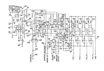
5FIGURE 1 is a electrical schematic diagram of
the ignition 6ystem of the present invention.
Detailed Description of the Invention
Broadly stated, the present invention relates to
an ignition ~y~tem ~or an internal combustion engine,
lo 6uch a~ an outboard engine for marine use or the like,
which ha~ superior operational characteristics. The
ignition ~ystem disclossd utilizes commercially available
and commonly known circuit components and combines such
components in an elegantly simple and superbly designed
circuit that results in superior operational characteris-
tic~, while utilizing a minimum number of circuit
elements.
The ignition system of the present invention is
adapted to function with portions of a capacitive
discharge ignition system that are well known and refined
over many years and are proven to be reliable. However,
the present invention provides improved safeguards and
protection against damage that could result from a
runaway overspeed condition as well a~ damage that could
result from advancing the ignition timing characteristic
when operating the engine above a predetermined speed,
such as about 1500 r.p.m~, for example. The present
invention provides ~or automatic advance of the timing
characteri~tic during startup and until smooth operation
is achieved, which aid6 in starting and in the initial
operation. In this regard, the advance i8 automatically
invoked ~or a short time period during initial operation
regardles~ o~ the t~mperature of the engine, i.e., even
: ,:
.' ' ' '-
~L2~6760
-5-
though the engine may have been running and was warm, and
also advances the ignition timing characteristic when the
engine is started cold and maintains the advance in
ef~ect until the enqine reaches a warmup temperature
within the range of about 80 to about 90 degrees F.
However, the advance is inhibited .if ths operating speed
reaches the predetermined speecl threshold as just
described.
While the present invention is particularly
adapted for use with outboard marine engines, as well as
other marine engines, it certainly is not limited to
applications involving only marine use. Also, while the
detailed description of the invention describes specific
circuitry to accomplish the operation of the system, it
should be understood that circuit functionality may be
accomplished by using similar components that may operate
using different voltage levels, or di~ferent components
to provide the same functionO Logic circuit elements can
have a "true" output that may be a voltage high or low,
for example, and the circuit could be modified to
: accomplish to same function.
Turning now to the drawing, a conventional timer
~ base for triggering the discharge of the ignition
:~ capacitor is shown at the upper right of the drawing and
includes a number of coils lOa, lOb, lOc and lOd (for a
four cylinder engine) and cooperate with a magnet (not
shown) preferably located on the flywheel for inducing a
voltage in the respective coils for discharging an
ignition capacitor 12 as the engine operates to produce
the normal ignition timing characteristic. There are
also a number of coils 14a, 14b, 14c and 14d that are
provided to produce an advanced ignition timing charac-
teristic, and this is achieved by placing the respective
coils 14 ahead of the coils 10 by a predetermined angle,
preferably about 10 degrees. If the ignition systsm has
. .:,
~LZ~`7 Ei(:~
-6-
the advance coils 14 in operation, the timing character-
i6tic ls advanced by the predetermined angle inasmuch as
the coils 14 will trigger the discharge sf the ignition
capacitor rather than the coils 10.
The capacitive diecharge ignition portion of the
circuitry operates identically with respect to each of
the cylinders that may be present ill the engine. In the
disclosed embodiment, there are ~our cylinders; the
circuitry fsr only one of the cylinders will be de-
~cribedO When coil lOa i~ passed in proximity to the
magnet, a voltage is induced in coil lOa which applied to
line 16, through diode 18 to line 20 and is applied to
the gate of an SCR 22, triggering it into conducl:ion and
discharges the previously charged ignitian capacitor
through a line 24, an SCR 26, a line 28, the SCR 22l a
line 30 to the spark plug of cylinder No. 1. The
; ignition capaaitor 12 i5 charged by a stator coil (not
~hown) connected through lines 32 and 34, a Sidac 36 and
diode bridge 38, one side of which is connected to the
capacitor 12 by a line 40, the other being connected to
the capacitor by line 24.
; ~o provide the advanced timing characteristic~
the coils 14 are enabled, and by virtue of their position
being angularly advanced relative to the coils 10,
trigger the discharge of the ignition capacitor by
approximately 10 degrees relative to the coils 10. This
i5 accomplished by a switching transistor 42 being
switched into conduction by the control circuitry portion
of the present invention. When transistor 42 is switched
into conduction, current flows through a line 44, diode
46, a line 48, a re6istor 50, a line 52, which is
connected to the gate o~ a SCR 54 and ~witches it on,
: which places coil 14a (as well as the other coils 14)
into operation ~o that coil~ 14 trigger the discharge,
rather than coils 10. Thu , when transistor 42 is
, .
12~671~i~
conducting, the aoil~- 14 which provide the advanced
ti~ing characteristic are placed in operation. Wh~n
tran~istor 42 i6 ~witched off, the igni~ion system
returns to itB nonadvanced timing characteristic.
In accordance with the pxessnt invention, the
control circuitry portion of the presenk invention
operates to cut out the ignition system so that damage
will not be done to the engine. Thi~ i~ done by prevent-
ing the ignition capacitor 12 ~rom charging. By prevent-
ing charging of the capacitor 12, the overall engine
: speed aan be controlled. In the praferred embodiment
disclosed, this is accomplished by a S~R 56 and a
resistor 5B connected in serie6 across the capacitor 12
by lines 24 and 40. When SCR 56 is switched into
conduction, tha ignition capacitor i5 shunted to ground,
and is there~ore prevented from ¢harg~ng ancl cannot
provide energy to the ~park plug when triggered by the
coil6 10 or 14.
The SCR 56 operation is co~trolled by a switch-
ing transi6tor 60 having its collector connected to the
gate of SCR 56 through a resistor 62. When the transis-
tor 60 is switched into conduction, the SCR S6 is
switched into conduction, which ehunts the capacitor 12
and prevents it from charging.
The power supply of the present invention, indi-
cated generally at 64, includes lines 66 and 68, which
are connected to a diode bridge 70, with a diac 72
connected between lines 66 and 68, and provides a 20 volt
output on line 74, which i~ regulated by transistor 76
and zener diode 78 a6 6hown, to provide a regulated 12
volt ~upply on line 80. The stator coil produces 6
pulses on line 68 ~or each revolution of the flywheel and
thereby provides a tachometer pulse on line 68 which is
applied through a capacitor 82, resistor 84 and line 86
: 35 to pin 1 of a fre~uency to voltage convertor 88. The
,,. . ~ -
~29~761D
convertor 88 has an output line 90 that ha~ a voltage
level that i~ directly proportional to the ~r~guency of
the pulses that are applied to its input on line 86. A
variable resi6tor 92 and resi6tor 94 define a voltage
bridge that varies the lev~l of the output voltage level
that is produced on the output line 90.
In accordance with an important aspect of the
present invention, the circultry provides protection
against a run-away speed condition occurring during
operation of the engine. This i8 accomplished by the
convertor 88 providing a voltage level on line 90 that is
utilized to switch the transistor 60 into conduction and
shunt the ignition capacitor 12. This ie accompli~hed by
the voltag~ on line 90 belng aonnected to one input of a
comparator 96 through rq6istor 98 and line 100. The
other lnput 102 comprises the referen~e voltage against
which the input on line 100 is compared, and the output
line 104 o~ the comparator 96 goes low (or approximately
0 volts) when the voltage on input line 100 is greater
than the re~erence voltage on line 102. In an operating
condition that does not represent an overhaat condition,
the voltage level on line 102 is designed to be ap-
proximataly 5 volts.
This voltage i8 ~upplied by the power supply
throuyh voltage reducing circuitry that will now be de-
scribed. The voltage level on line 80 has been previous-
ly described as being approximately 12 volts. Line 80 is
connected through a resistor to a line 108 that is
connected to a zener diode 110 and a regulated voltage of
approximately 9 volt~ i5 applied on line 108. The line
108 is aonnected to a resistor 112, which ~n cooperation
with a re6i~tor 114, funotions as a voltage divider and
provides a voltage of approximately 5 volt9 on a line
: 116. Lin~ 116 i~ connected to the line 102 through a
resistor 118, and applies a voltage of approximately 5
- :~Z~ 60
g
voltE to the reference voltage input o~ the comparator
96. The output line 104 of the comparator 96 i8 con-
nected to the ba~e of ths transi~tor 60 via a resistor
120 and line 122.
S During operation, the convertcr 88 produces a
voltage on output line 90 that i~ applied to one input of
the comparator 96. When the speed reaches a ~peed of
approximately 6000 r.p.m., the comparator 96, comparing a
reference voltage o~ approximately 5 volts, produces a
low voltage on output line 104 that re~ults in transistor
60 switching on, thereby shunting ignition capacitor 12
and limiting the speed of the engine. Protection against
a run-away ~peed condition is provided by a relatively
~ew number o~ circuit component~
It ~hould be understood that the 6hunting o~ the
ignition capacltor 12 may occur ~or in~remental short
periods oP time and on a ~requent basis. I~ the speed is
close to the run-away speed condition, as soon as the
overspeed conditions is detected, the shunting will occur
and the speed will quickly drop. When the operating
speed drops below th~ detected threshold, the transistor
60 will be switched off, and the ignition capacitor will
no longer be shunted. Thus, as a practical matter, the
engine speed may be modulated around the threshold speed
that triggerR the comparator 96.
; In accordance with another important aspect of
the present invention, the maximum speed of operation is
reduced from approximately 6000 r.p.m. to about 2500
r.p.m. if an overheat condition is detected. This is
acccmplished u~ing the same comparator 96 ln combination
with temperature sensing circuitry. In this regard, a
light emitt~ng diode (LED) 124 i8 optically coupled to a
opto-SCR 126. The LED 124 ie connected to a 20 volt
supply on line 74 through a resistor 128, and to ground
through a diode 130 and an overheat temperature switch
~Z96~760
--10--
132. The switch 132 is positione~ to sense the engine
temperature and is adapted to close at a temperature of
about 212 degrees F. When the ~witch 132 i8 closed, LED
-- 124 iB turned on, placing opto-SCR :into conduction. This
then lowers the reference voltage applied to the refer-
ence terminal of th~ comparator 96 to a level of ap-
proximately 2.3 volts. The lower reference results in a
low output being produced on line 104 at a lower operat-
ing speed, as i6 intended. In op~ration, when an
o~erheat condition is detected, the comparator 96
switches low at an operating speed of about 2500 r.p.m.,
and thus ~hunts the ignition capacitor to limit the speed
a~ previously dsscribed, although at a speed of about
2500 r.p.m. rather than about 6000 r.p.m.
The nature of the operation of the opto-SCR is
such that it will not be turned off until power is
removed from the circuit, and this will not occur until
the engine is turned off. This feature iB desirable in
that it prevents the circuitry from cycling on and off at
or about the critical overheat temperature.
Another important attribute of the present
invention lies in the provi6ion of automatically provid-
; ing an advance in the timing characteristic when the
engine is ~nitially started and until the engine reaches
a predetermined minimum warm-up temperature. This is
; accomplished by circuitry that controls the 6witching of
the translstor 42~ With respect to the warm-up aspect of
the circuit operation, a line }34 is connected to a warm-
up switch 136 to ground, and switch 136 closes when the
sen ed engine temperature exceeds a temperatur~ within
the range of about 80 to about 90 degree~ F. The line
134 is normally high, but goes low when tha engine warms
up sufficiently to close the switch 136. ~he line 134 is
connected to the comparing input line 138 of a comparator
140 through a resistor 142. Comparator 140 provides a
~296760
high output on line 144 when input line 138 i~ high. The
line 144 is connected to an input li.ne 146 of an AND gate
148 via resi~tor 150. The other input line 152 to AND
gate 148 i~ normally high until a predetermined speed is
rsach by the engine as will be subsequently described, an
AND gate provides a high output Oll line 154 when input
linea 146 and 152 are hi~h. The line 154 is connected to
the base o~ transistor 42 and to the collector thereof
via a resi~tor 156 and a line 158. When the AND gate
output i8 high, the transistor 42 is witchad into
conduction, which activates the advanced timing charac-
teri~tic as has been previously described. From the
~oregoing, it ~hould be understood that the engine will
be operated in the advanced timing characteristic until
the engine wa~ms up to an operating temperature of about
80 to about 90 degrees. When ~witch 136 closes, the
input 138 will be pulled low, thereby switching com-
parator 140 low and producing operation in the normal
nonadvanced ignition timing characteristic.
As previously described, the engine will also
: operate in its advanced timing characteri~tic for a hort
:~ predetermined time period after initial start-up, i.e.,
for approximately 5 to 10 seconds, regardless of the
temperature of the engine. This iB accomplished by
having the starter solenoid (not shown) apply a voltage
: to charge a capacitor 160 via a line 162, a diode 164 and
a line 166. The line 166 i~ connected to the input line
138 to the comparator 140 via resistor 16B. Upon
~tarting of the engine the starter solenoid will charge
the capacitor 160 which will provide a high level on
input line 138 and place the engine in the advanced
timing characteristic mode of operation for the time
period reguired to discharge the capacitor to a level
where the comparator 140 i8 switched low. In the
illustrated embodiment, this is prefPrably about 7
~ .,
. - ' ~
lZ96760
-12-
6eoonds, although the circuit components can be chosen to
provide a longer or short time period if desired.
In accordance with yet another important aspect
of the present invention, provision is made to automa-
tically inhibit the ad~anced timing characteristic i~ theoperating speed of the engine exceeds a predetermined
level o~ approximately 1500 r.p.~. in the preferred
embodiment. Operating the engine with the ignition
advanced above this epeed could re~;ult in damage to the
engine.
To inhibit the advanced timing characteristic,
the convertor output 90 i8 connected to the comparing
input 100 of a comparator 170, the raference input 172 of
which i~ connected to line 116 via a resistor 174. The
re~erence voltage i~ chosen to cau~e the comparator to
have its output line 176 switched low when the comparing
voltage increases to a level to switch the comparator at
an operating speed of approximately 1500 r.p.m.. When
output line 176 is low, it removes a high voltage applied
to the AND gate 148, thereby cau6ing it to switch and
provide a low output which switche6 transistor 42 off and
removes the engine from it6 advance timing characteristic
mode of operation. Thua, the circuitry always prohibits
operation in an advanced timing mode above approximately
1500 r.p.m., even if the engine i8 not warmed up or
exceeds a running speed of 1500 r.p.m. within the time
period of approximately 7 seconds.
From the foregolng description of the circuitry
of the present invention, it iB apparent that the power
for operating the control circuitry i5 obtain~d ~rom tbe
~tator coil inducing a voltage that is regulated to power
; the circuitry. During initial start-up, the cranking
speed may not be aufficient to provide reliable voltage
levels to in6ure rellable aircuit operation. Provision
is made to supplement the output of the power supply with
~, Z9~76~9
, .~
-13-
power supplied from the etarter solenoid during cranking.
This iB accomplished by coupling the starter solenoid
voltage on line 162 to line 74 via the diode 164, line
166 and a diode 180.
An ignition system for an internal combustion
engine ha6 been described which ha~ many desirable
positive features in terms of itB design and operation.
Many attributes of the system are carried out using a
circuit de~ign that utilizes a relative conservative
number of components and yet performs many desirable
functions.
It is of course undexstood that although
preferred embodiments of the present invention have been
illustrated and de~cribed, various modifications thereof
will become apparent to those ~killed in the art and,
accordingly, the scope of khe present invention should be
defined only by the appended claims and equivalents
thereof.
Various features of the present invention are
set out in the appended claims.
.