Note: Descriptions are shown in the official language in which they were submitted.
fi9~_
EXTENDABLE ELECTROCAUTERY
SURGERY APPARATUS AND METHOD
Related Case
The subject matter of this application is related
5to the subject matter of U.S. Patent No. 4,307,720.
Backqround of the Invention
Field of Invention
This invention relates to electrocautery surgical
instruments and more particularly to an electrocautery
scalpel system having variably extendable suction and
electrode elements to facilitate electrocautery surgery
at deep locations within surrounding tissue.
Electrocautery instrument commonly rely upon high-
voltage, high-frequency electrical signals of various
waveforms ~o selectively sever, clamp or coagulate
living tissue during surgical procedures. In addition,
many such electrocautery instruments include integral
vacuum conduits and associated suction apparatus for
evacuating tissue fluids and volatized tissue materials
that commonly accompany electrocautery incision of
living tissue. Devices of these types are disclosed in
the literature (see, for example, U.S.
~,
3~
~atents 1,311,494; 1,963,636; 2,002,594; 2,394,512; 3,662,151;
3,682,162; 3,82~,7B0; 3,835,842; 3,850,175; 3,884,237;
3,902,494; 3,906,955; 3,974,833; 3,9B7,795; 4,011,872;
4,112,950; and 4,562,838; and French Patent No. 73.30854).
Electrocautery instruments of these types also commonly employ
a retractable electrode or a vacuum port to enhance the utility
of the instrument during surgical procedures. One difficulty
encountered with certain electrocautery scalpels having
extendable and retractable electrodes is that the geometry of
the instruments usually limits the depth in tissue to which the
instruments can conveniently penetrate without e~panding the
incision to accommodate the surgeon's hand. As certain
surgical procedures progress and penetrate deeper into a
surgical site, it is frequently desirable to extend the
instrument to longer dimension with control over the
retractable electrode in order to facilitate advancing the
surgery into deep, confined sites.
Summarv of the Invention
In accordance with the present invention, an improved
electrocautery surgical instrument includes a retractable
electrode and a vacuum conduit for selectively evacuating a
surgical site, and also includes attachable extension units of
various lengths for selectively estending the operational
utility of the instrument as a surgical procedure progresses.
The vacuum port and slidable electrode/blade of the i~strument
are thereby extended a selected dimension to facilitate deep
-- 2
;96;~
surgical procedures in confined sites. Safety switching
is included within the instrument to control application
of high-voltage electrical signals to the
electrode/blade and to permit the user to establish
electrically inactive conditions during attachment and
removal of extension units. The electrocautery surgical
instrument thus configured according to the present
invention facilitates surgical procedures in deep
surgical sites as well as in shallow surgical sites
without having to replace the instrument in the
surgeon's hand during the surgical procedure.
Various aspects of this invention are as follows:
Surgical apparatus comprising:
an elongated body having an electrical conductor
positionable along a slideable path extending
substantially therethrough toward a forward end thereof,
and including connector means disposed near said forward
end;
said connector means being disposed to receive a
conductive element therein for selective slideable
positioning thereof relative to said forward end in
response to slideable movement of the electrical
conductor;
slider means disposed on the body and coupled to
the electrical conductor for selectively altering the
position thereof and of the connector means between
forward and rearward positions thereof relative to said
forward end;
circuit means disposed in the body to be actuated
by the electrical conductor for controlling the
application of electrical signal thereto in response to
the position of the electrical conductor along the
slideable path thereof;
said circuit means including an interlock switch
operable in conductive state and in non-conductive state
and disposed to be actuated for operation in the non-
conductive state in response to the electrical conductor
.,
~25~96:~
3a
being positioned near said rearward position along the
slidable path thereof; said interlock switch including
auxiliary circuit means disposed in the body for
grounding the electrical conductor during operation in
said non-conductive state.
Surgical apparatus comprising:
an elongated body having an electrical conductor
positionable along a slideable path extending
substantially therethrough toward a forward end thereof,
and including connector means disposed near said forward
end;
said connector means being disposed to receive a
conductive element therein for selective slideable
positioning thereof relative to said forward end in
response to slideable movement of the electrical
conductor;
slider means slideably disposed on the body and
coupled to the electrical conductor for selectively
altering the position thereof along the slideable path
and of the connector means between forward and rearward
positions relative to said forward end;
circuit means disposed in the body to be actuated
by the electrical conductor for controlling the
application of electrical signal thereto in response to
the position of the electrical conductor along the
slideable path thereof;
switch means including at least one switch mounted
in the body and including an actuator therefor
positioned on the body for manually actuating said one
switch for selectively applying electrical signal
through said circuit means to the electrical conductor;
and
said slider means including means oriented to
shroud the actuator against manual operation thereof
near the rearward position along the slideable path
thereof.
'~b
lX.'t~;96~
3b
Surgical apparatus comprising:
an elongated body having an electrical conductor
positionable along a slideable path extending
substantially therethrough toward a forward end thereof,
and including connector means disposed near said forward
end;
said connector means being disposed to receive a
conductive element therein for selective slideable
positioning thereof relative to said forward end in
response to slideable movement of the electrical
conductor;
slider means disposed on the body and coupled to
the electrical conductor for selectively altering the
position thereof and of the connector means between
forward and rearward positions thereof relative to said
forward end;
circuit means disposed in the body to be actuated
by the electrical conductor for controlling the
application of electrical signal thereto in response to
the position of the electrical conductor along the
slideable path thereof;
a vacuum conduit through the body including a port
near said forward end thereof;
valve means for said vacuum conduit including a
control element disposed to protrude from said body of
manually controlling vacuum at said port;
said port including a receptacle which extends to
said forward end of the body for receiving a conduit in
a front end thereof near said forward end of the body
and including an aperture in the receptacle that
communicates with the vacuum conduit for limiting the
pressure in the vacuum conduit when said front end of
the receptacle is occluded:
extension means including a conduit for attachment
to the receptacle and electrode means for attachment
with said connector means for conducting electrical
signal therefrom, and including support means attached
'~b
'3~i~
to the conduit for slideably supportiny the electrode
means therein;
said extension means disposed to attach to said
body with the conduit thereof inserted into said
receptacle to occlude said aperture and with the
electrode means attached to said connector means.
Surgical apparatus comprising:
an elongated body having an electrical conductor
positionable along a slideable path extending
substantially therethrough toward a forward end thereof,
and including connector means disposed near said forward
end;
said connector means being disposed to receive a
conductive element therein for selective slideable
positioning thereof relative to said forward end in
response to slideable movement in the electrical
conductor;
slider means disposed on the body and coupled to
the electrical conductor for selectively altering the
position thereof and of the connector means between
forward and rearward positions thereof relative to said
forward end;
circuit means disposed in the body to be actuated
by the electrical conductor for controlling the
application of electrical signal thereto in response to
the position of the electrical conductor along the
slideable path thereof;
support means for supporting an electrode therein
disposed to be attached to said body near said for~ard
end thereof; and
electrode means for conducting electrical signal
slideably disposed in the support means and including a
portion thereof disposed to protrude from a forward end
of the support means in a forward slideable position
thereof and having a rearwardly extending portion
disposed to attach to said connector means.
,~
i96;~
3d
Surgical apparatus comprising:
an elongated body having a~ electrical conductor
positionable along a slideable path extending
substantially therethrough toward a forward end thereof,
and including connector means disposed near said forward
end;
said connector means being disposed to receive a
conductive element therein for selective slideable
positioning thereof relative to said forward end in
response to slideable movement of the electrical
conductor;
slider means disposed on the body and coupled to
the electrical conductor for selectively altering the
position thereof and of the connector means between
forward and rearward positions thereof relative to said
forward end;
circuit means disposed in the body to be actuated
by the electrical conductor for controlling the
application of electrical signal thereto in response to
the position of the electrical conductor along the
slideable path thereof;
a vacuum conduit through the body including a port
near said forward end thereof;
valve means for said vacuum conduit including a
control element disposed to protrude from said body for
manually controlling vacuum at said port;
support means for supporting a vacuum port near a
forward end thereof and having a conduit coupled thereto
and extending rearwardly from the support means for
attachment to said port of said body; and
electrode means for conducting electrical signal
slideably disposed in the support means and including a
portion thereof disposed to protrude from said forward
end of the support means in a forward slideable position
thereof, and having a rearwardly extending portion
disposed to attach to said connector means of said body.
' ~2~
, . ~ .
A method of operating an electrosurgical instrument
including a vacuum conduit with a port disposed in a
forward end of the instrument and including a manually-
controlled slideable electrode extendable from said
forward end for controllably applying electrical signal
to tissue, the method comprising the steps of:
detachably substituting electrode means for the
electrode to extend from said forward end of the
instrument;
detachably extending the vacuum conduit from the
port in said forward end of the instrument to an
extended port at a location near the electrode means;
and
slideably supporting the electrode means near the
extended port of the vacuum conduit for selectively
manually extending the electrode means relative to said
location in response to the manual control thereof at
the instrument.
Description of the Drawinas
Figure 1 is a partial perspective view of the
electrocautery surgical instrument with an attached
extension unit; and
Figure 2 is a side view of the extension unit of Figure
l; and
Figure 3 is a partial sectional assembly view of the
extension unit of Figure 1; and
Figure 4 is an exploded assembly view of the instrument
of Figure l; and
Figure 5 is a sectional view of the interlock switch of
Figure 4: and
Figure 6 is a sectional view of another embodiment of
the interlock switch according to the present invention.
Figure 7(a) and (b) are plan and sectional views,
respectively, of the body of the electrode scraping means:
and
;9~, ~
Figures 8(a) and (b) are plan and side views,
respectively, of a flat, blade-like electrode for assembly
within the body of Figure 7.
Description of the Preferred Embodiment
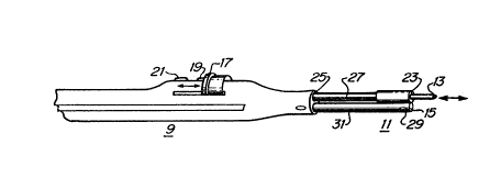
Referring now to Figure 1, there is shown a
perspective view of the electrocautery instrument 9 with an
extension unit 11 attached to the front end of the instrument.
Specifically, the retra~table electrode/blade 13 is extended
forward and is retractable within the extension unit 11, and
the vacuum port 15 is also extended forward from the instrument
9 to provide substantially the same blade 13 and port 15
characteristic at the front of the extension unit 11 as are
available on the front of the instrument 9 without the
extension unit 11 in place. The extension units 11 may be of
variable length as desired to facilitate deep surgical
procedures, and may ~e attached and removed as desired by
press-fit or snap-toggle attachment on the front of the
instrument 9. A manually-slidable element 17 is attached to
the electrode 13 to control the extent of the protrusion of the
electrode 13 from the front of the instrument 9, or from the
front of the attached estension unit 11. Push buttons 19 and
21 are provided to control application of different
high-voltage, high-freguency waveforms to the electrode 13 for
either incising or cauterizing tissue in known manner. In
addition, the guide opening for the electrode 13 at the front
of the extension unit 11 may be disposed closely about the
-- 4 --
l~~fi9~i~
'~lade 13 to scrape off adherent coagulum and tissue materials
as the electrode is retracted therethrough in response to
manual activation of the slide element 17. The portion 27 of
electrode 13 that is exposed is insulated to facilitate
manipulation of the instrument within surrounding tissue
without undesirably discharging electrical signals to
surrounding tissue in the region 27 between the electrode 13
and the front~of the un1t 9. A decompression port 29 is
disposed in at least one lateral dimension from the vacuum port
15 to control the maximum pressure differential that can be
developed at the vacuum port 15 under conditions of the port 15
being occluded by tissue which might be damaged by excessive
suction.
~ eferring now to Figure 2, there is shown a side view
of the extension unit 11. The lower tube 31 is the vacuum
conduit with the vacuum port 15 and decompression port 29. The
upper electrode 13 and connecting conductor 33 is insula~ed 35
over the region 27 that extends between the instrument 9 and
the exposed electrode 13. The body 37 of the extension unit 11
may be ~elded, glued or otherwise attached to the vacuum tube
31, and serves as a guide for the electrode 13 which is
slideably mounted therein. The electrode 13 may be
needle-like, or generally flat (i.e., its width is greater than
the thickness) to serve as a surgical blade. The body 37 may
include a scraping guide 39 for removing adherent coagulum and
tissue material as the electrode 13 and the conductor 33 to
which it is attached is withdrawn into and through the body 37.
-- 5 --
1 ~!t~
The sectional view of Figure 3 illustrates the
attachment of the vacuum tube 31 to the body 37. Also, the
electrode~blade 13 portion of the conductor 33 is shown
disposed to slide within the guide way 41 in the body 37
through and past the scraping means 39 at the forward end
thereof. Alternative embodiments of scraping means are
described herein with reference to Figures 7 and 8.
Referring now to the exploded assembly drawing of
Figure 4, there is shown the internal features of the
instrument 9 which accommodate attachment of the extension unit
11 on the front end thereof. Specifically, the right and left
half sections 43, ~5 of the instrument 9 are disposed to house
the switches, electrode, manual slider, vacuum conduit and
valving, and associated wiring to form the electrocautery
instrument when assembled as shown. The vacuum conduit or
suction tube 47 in the lower portion of the sections 43,45 is
positioned in fluid-tight engagement 49 with the vacuum port 51
in the forward end of the instrument 9, which vacuum port has
an inner diameter ~or other cross-sectional dimensions) that
receive therein the attachment end of the vacuum conduit 31 of
the estension unit 11 in press-fitted, fluid-tight engagement.
Alternatively, jam taper fit, or threaded engagement, or
snap-fitting o-ring on an annular recess may be used to seal
and secure the instrument and extension unit together as well
as form a continuation of the vacuum conduit 47, 31. Also, the
vacuum port 51 of the instrument 9 may have a decompression
.~
~ort 53 for limiting the pressure differential at the port, as
previously descri~ed with reference to the ports lS, 29 on the
extension unit 11. This decompression port 53 is disposed
within a socket or receptacle of the vacuum port 51 to be
sealed off by insertion into such socket or receptacle of the
connecting end of the vacuum conduit 31 of the estension unit
11. The vacuum conduit is therefore extended forward to the
vacuum and decompression ports lS, 29 of the estension unit 11
when the extension unit 11 is properly attached to the front of
the instrument ~. This vacuum conduit may be connected via a
suitable control valve such as a roller 55 disposed to manually
pinch off the flexible conduit 47 that connects to a remote
vacuum supply (not shown). In this way, the operating surgeon
may control the application of suction at a surgical site by
positioning the vacuum port 15 (or 51, if an extension unit 11
is not attached) and by manually rotating the pinch roller 55
to selectively pinch off the flexible conduit 47, and thereby
control the vacuum action at the port 15.
In the upper portion of the instrument 9, the slide
element 17 is disposed to slide longitudinally in tracks or
grooves 61 in the body of the instrument 9. The tab 68 that
protrudes from the slide element 17 through a groove 65 engages
the slide electrode 100 at the recess 101 to thereby control
retraction and extension of the electrode 71 under manual
control of the slide element 17. The electrode conductor 69,
in one embodiment of the present invention, may slide in
electrical contact through contactor 67 to engage the safety
-- 7 --
1 ~t~ 3~i~
witch 85 in its rearward-most retracted position. The
electrode 71 attaches 73 to the slide electrode 100 at the
forward end thereof ~or gripping the electrode/blade 71 (or the
contact end 33 of the electrode conductor 35 of an extension
unit 11) by friction or snap-toggle engagement, or the like, in
known manner. ~he switch plate 63 includes conventional
dome-type switches 79, 81 which may be activated by the push
buttons 75, 77 that are mounted in the body of the instrument
9. Thus, the push-button switches 79, 81 may be manually
activated when the slide element 17 (and therefore the
electrode/blade 71 or 13) is positioned in the forward
location. In the rearward position of the slide element 17,
one or more of the push-button switches 79, 81 are shrouded by
the slide element 17 as protection against inadvertent manual
activation. Additionally, the rearward end of the electrode
conductor 69, 71, i5 disposed to engage an interlock switch 85
that is wired into the circuit including the electrode and a
source (not shown) of high-frequency, high-voltage electrical
signals. Thus, electrical signals for either severing or
cauterizing tissue are connected from such source via a cable
87 (which may be integral with the vacuum conduit for
convenience) to the switches 79, 81 on the switch plate 63.
The interlock switcb 85 is thus disposed to cut off the
application of all electrical signals when the electrode
conductor 69 is in the rearward-most position. In this
position, the slide element 17 shrouds either or both of the
push buttons 75, 77 as a further safety interlock feature
while the electrode is withdrawn rearwardly into the ~sdy of
-- 8 --
.he instrument 9 (or into the body 37 of an e~tension unit
11). Scraping ~eans 89 as illustrated in Figure 7, may be
disposed about the electrode~blade 71 to dislodge adherent
coagulum and tissue material as the electrode/blade 71 is
withdrawn into the body under manual control of the slide
element 17. Thus, during operating procedures, the
electrode/blade 71 (or 13 of an extension unit 11) may be
withdrawn into the body of the instrument 9 (or of the
e~tension unit 11) under manual control of the slide element 17
to clean the blade and to configure the front end of the unit
to facilitate its use simply as a vacuum probe to evacuate a
surgical site. In this configuration, the push buttons 75, 77
are shrouded against inadvertent activation, and the roller 55
may be manually activated to pinch and unpinch the flexib!e
tubing 47, as desired. Alternatively, the electrode 71 (or 13
of an extension unit 11) may be advanced under manual control
of the slide element 17 to protrude from the instrument 9 (or
extension unit 11). In this configuration, the push buttons
75, 77 are exposed and may be manually activated to control the
supply of either severing or coagulating electrical signals to
the electrode/blade via the interlock switch 85.
Referring now to Figure 5, there is shown a sectional
view of one emodiment of the interlock switch 85 which is
disposed within an enclosing housing 91 to be actuated by the
rearward end of the electrode conductor 69. Thus, the control
leads 93, 95 (which may conduct low-voltage control signals~
from the push button switches 79, 81 on the contact plate 63
connect via the cable 87 to a conventional source (not shown)
g _
1 ~t~
f high-voltage, high-frequency signal, and such signal is thus
suppli~d through a powe~ ~anduc~or 86 in the ra~le 87 aDd
through contact 84 of the interlock switch 85 to the switch
plate 63, slide contactor 67, and electrode 71 (or 13). In the
rearward-most or retracted position of the electrode conductor
69, the power conductor 86 may be shunted to ground through
alternate contact 88 and a ground conductor 90 in the cable 87.
In another embodimen~ of the interlock switch 85
according to the present invention, as illustrated in the
sectional view of Figure 6, the electrode conductor 69 of
Figure 4 is formed in a printed-circuit like structure 103
including a non conductive central region 105 having a recess
107 to receive the tab 68 of the slide element 17, and a
rearward section 109 that includes a conductor 110 disposed on
an insulating layer 112. The conductor 110, of course,
connects to the attaching means (or universal chuck) 73, and is
slideably engaged by contacts 114 and 119. Electrical signal
on contacts 114 .(from a signal generator not shown) is applied
to the electrode 71 ~or 13 of an extender unit) while such
electrode is in extended position under the manual control of
the slide element 17. However, the insulating layer 112 of the
electrode conductor 69 includes an aperture 116 at a location
approrimately at the ma~imum rearward estent of travel (i.e.
retracted electrode) and in line with the contact 114 .
~nother sliding contact 118 is disposed to connect to the
contact 114 only within the aperture 116, and to be insulated
therefrom by the insulating layer 112 otherwise. In the
-- 10 --
;9~
etracted position of structure 103, the slidinq contact 119
may also be i~sultated ~y 112 ~ro~ con~uct~I ~20 ~5ed upon the
particular pattern of the conductor 110. Contact 118 may be
connected back to ground via the shield on cable 87.
Therefore, the electrode 13 may be effectively grounded while
in the retracted position to prevent inadvertent electrical
excitation of the electrode blade 71 (or 13) during
configuration and use o the instrument as a vacuum probe, or
during attachment of detachment of an extension unit.
Referring now to Figure 7 a and b, here are shown
plan and sectional views, respectively, of the scraping means
B9 for guiding and scraping the electrode blade illustrated in
Figures 8a and b. Specifically, these views illustrate the
ferrule-like structure 89 of Figure 7 that may conveniently
snap into place near the forward edge of the instrument (or of
an extension unit) for easy replacement of electrodes of
different configurations (e.g. flat or needle-lihe). Thus, the
scraping means 89 includes a generally hollow body through
which the electrode 13 of Figure 8 slides, and includes a
clcse-fittinq forward aperture 121 which engages the blade
portion 123 of the electrode 13 is sliding, contacting
relationship. The rear portion of the body 89 includes
resilient jaws-like structure 125 to facilitate assembly of the
electrode 13 (including the section 127 of expanded diameter)
into the body from the rearward end toward the forward end.
The jaws-like structure return to position to retain the
electrode 13 ent,rely to captivated and slideable within the
body 89. The section 127 is received by and retained in the
ttachement means 73 to facilitate the mechanical sliding
motio~n ~f t~e el~ctrode 13 within the body ~9-under ma~ual
control of the user. Spring-like protrusions 129 formed on the
body 89 about its central section facilitate the snap-in
retention of the body 89 and captivated electrode 13 within and
near the forward end of the instrument. ~hus, electrodes 13 of
different shapes and lengths may be conveniently inserted in
and removed from the instrument ~or e~tension units) as the
suryical operation proceeds.
In operation, the instrument 9 (with or without
attached extension unit 11) may be configured to operate either
as a vacuum probe alone (with the electrode/blade 71, 13
retracted) or as an electrosurgical instrument with the
electrode/blade 13, 71 extended into operational position. In
the latter configuration, the electrical control buttons are
exposed and the safety, interlocking switch is actuated to
permit high-voltage, high-frequency electrical signals to be
supplied to the protruding electrode~blade under control of one
or more of the uncovered, exposed push buttons. The
operational length of the instrument may be altered by
attaching or detaching estension units of desired length. The
vacuum port of the instrument is altered by attachment of an
extension unit, and the electrode/blade of the estension unit
is electrically connected and mechanically attached for
convenient manual e~tension and retraction csntrol from the
instrument.
Therefore, the method and apparatus of the present
invention facili-t~t4s the convenient ~ten~ion of an
electrocautery surgical instrument to accommodate surgical
procedures performed deep within surrounding tissue while
providing interlock features that enhance the safety and
utility of the instrument during attachment and detachment of
e~tension units and during its operation as a vacuum probe.