Language selection

Search

Patent 1296964 Summary

Third-party information liability

Some of the information on this Web page has been provided by external sources. The Government of Canada is not responsible for the accuracy, reliability or currency of the information supplied by external sources. Users wishing to rely upon this information should consult directly with the source of the information. Content provided by external sources is not subject to official languages, privacy and accessibility requirements.

Claims and Abstract availability

Any discrepancies in the text and image of the Claims and Abstract are due to differing posting times. Text of the Claims and Abstract are posted:

  • At the time the application is open to public inspection;
  • At the time of issue of the patent (grant).
(12) Patent: (11) CA 1296964
(21) Application Number: 1296964
(54) English Title: HARVESTER-THRESHER WITH AN APPARATUS TO SPREAD THE GRAIN-CHAFF MIXTURE
(54) French Title: MOISONNEUR AVEC DISPOSITIF POUR L'EPANDAGE DE MELANGE GRAIN-PAILLE
Status: Expired and beyond the Period of Reversal
Bibliographic Data
(51) International Patent Classification (IPC):
  • A01F 29/12 (2006.01)
  • A01D 41/12 (2006.01)
(72) Inventors :
  • GLAUBITZ, FRANZ (Germany)
  • HARIG, HORST (Germany)
(73) Owners :
  • CLAAS OHG
(71) Applicants :
  • CLAAS OHG (Germany)
(74) Agent: SMART & BIGGAR LP
(74) Associate agent:
(45) Issued: 1992-03-10
(22) Filed Date: 1988-02-15
Availability of licence: N/A
Dedicated to the Public: N/A
(25) Language of filing: English

Patent Cooperation Treaty (PCT): No

(30) Application Priority Data:
Application No. Country/Territory Date
P 37 04 755.8 (Germany) 1987-02-16

Abstracts

English Abstract


ABSTRACT
A harvester-thresher has an apparatus to spread
the grain-chaff mixture that comes from the sieve box
over the whole width of the cutter swath which, as is
known, is considerably wider than the actual harvester-
thresher. To this end, the housing, which encloses the
discs with the spreader bars on the periphery and on a
face side, defines an additional air-inlet opening, so
that a partial vacuum is formed in the area of the
spreader bars, this partial vacuum drawing the grain-chaff
mixture into the spreader apparatus.


Claims

Note: Claims are shown in the official language in which they were submitted.

THE EMBODIMENTS OF THE INVENTION IN WHICH AN EXCLUSIVE
PROPERTY OR PRIVILEGE IS CLAIMED ARE DEFINED AS FOLLOWS:
1. A harvester thresher comprising grain cleaning means
having a discharge end; and means for distributing a grain-chaff
mixture arranged in the region of said discharge end of said grain
cleaning means, said distributing means having two oppositely
rotatable discs and a cup-shaped housing which surrounds said
discs and has at least one throwing out opening and a bottom, said
bottom of said cup-shaped housing having a central air supply
opening, each of said discs of said distributing means being
provided with a distributing strip attached to said disc, said
bottom of said housing is formed as a cover provided with said
central air supply opening, said cup-shaped cover also having an
open end facing towards said grain cleaning means, said discs
having one side facing toward said grain cleaning means and being
provided at said one side with said distributing strips, said disc
also having another side facing towards said cover of said cup-
shaped housing and being provided at said another side with a
plurality of air vanes.
2. A harvester thresher comprising grain cleaning means
having a discharge end; and means for distributing a grain-chaff
mixture arranged in the region of said discharge end of said grain
cleaning means, said distributing means having two oppositely
rotatable discs and a cup-shaped housing which surrounds said
discs and has at least one throwing out opening and a bottom, said

bottom of said cup-shaped housing having a central air supply
opening, said housing having two separate cup-shaped housing parts
each surrounding a respective one of said discs of said
distributing means, each of said discs having an axis of rotation,
each of said separate housing parts being supported turnably about
said axis of rotation of a respective one of said discs.
3. A harvester thresher comprising grain cleaning means
having a discharge end; means for distributing a grain-chaff
mixture arranged in the region of said discharge end of said grain
cleaning means, said distributing means having a drive shaft, two
oppositely rotatable discs driven from said drive shaft and a cup-
shaped housing which surrounds said discs and has at least one
throwing out opening and a bottom, said bottom of said cup-shaped
housing having a central air supply opening; machine walls; and a
hollow profile mounted on said machine walls and surrounding said
drive shaft of said distributing means, said housing being
turnably connected with said hollow profile.
4. A harvester thresher as defined in claim 2, wherein each
of said discs of said distributing means is provided with a
distributing strip attached to said disc.
5. A harvester thresher as defined in claim 1, wherein said
cup-shaped housing has a peripheral region, said at least one
throwing out opening being arranged in said peripheral region of
said cup-shaped housing.

6. A harvester thresher as defined in claim 1, wherein said
housing has two separate cup-shaped housing parts each surrounding
a respective one of said discs of said distributing means.
7. A harvester thresher as defined in claim 1, wherein said
cup-shaped housing has a peripheral cover forming with said disc a
throughgoing annular gap for air.
8. A harvester thresher as defined in claim 3, and further
comprising connecting means for turnably connecting said housing
with said hollow profile and including screw means.
9. A harvester thresher as defined in claim 1, and further
comprising a drive shaft arranged to drive said discs.
10. A harvester thresher as defined in claim 9, and further
comprising a hollow profile connecting with said housing and
accommodating said drive shaft for driving said discs.
11. A harvester thresher as defined in claim 10, and further
comprising means for transmitting rotation of said drive shaft to
said discs and including axles connected with said discs and
rotatably supported in said hollow profile, spur gears arranged on
said axles, and bevel gears mounted on said drive shaft and
engaging with said spur gears.

Description

Note: Descriptions are shown in the official language in which they were submitted.


12~ 364
The present invention relates to a harvester-
thresher that incorporates an apparatus to spread the grain-
chaff mixture.
Such apparatus may comprise two counter-rotating
discs that are fitted with spreader bars, these discs and
the bars fitted thereon being enclosed by a housing having
at least one ejection opening on its periphery, the whole
unit being arranged at the output end of the grain-cleaning
apparatus.
Spreaders of this kind are known, for example, from
US patent 4,526,180. In and of themselves, they work
satisfactorily as long as they are used to spread relatively
heavy particles of the substance involved. Lighter particles
of this substance do not even get into the impact area of
the spreader bars because the air turbulence generated by
the bars also acts as a buffer that the light particles
cannot penetrate. These light particles are carried along
in a completely uncontrolled manner, partly by the material
that is being ejected and partly by the particles that
follow this material, and finally fall to the surface of
the ground close to the machine.
Thus it is the aim of the present invention to so
configure a harvester-thresher of the type described in the
introduction hereto that the grain-chaff mixture is spread

i4
evenly ~.o a width that corresponds to the swath of the harvester-
thresher, even though the cutter system swath itself ls wider than
the harvester-thresher.
The invention also provides a harvestar thresher
comprisinq grain cleaning means having a discharge end; and means
for distributing a grain-chaff mixture arranged in the region of
said discharge end of said grain cleaning means, said distributing
means having two oppositely rotatable discs and a cup-shaped
housing which surrounds said discs and has at least one throwing
out opening and a bottom, said bottom of said cup-shaped housing
having a central air supply opening, said housing having two
separate cup-shaped housing parts each surrounding a respective
one of said discs of said distributing means, each of said discs
having an axiæ of ro~ation, each of said separate housing parts
being supported turnably about said axis of rotation of a
respective one of said discs.
The present invention is described in greater detail
below by way of example only, on the basis of the drawings
appended hereto, wherein:
Figure 1 is a side view of the rear section of a
harvester-thresher fitted with a spreader system;
Figure 2 shows the spreader system as shown in Figure 1,
in modified form;
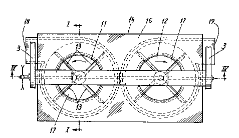
Figure 3 is a plan view of the spreader system shown in
Figure 1;
Figure 4 is a cross-section taken on the line IV-IV in
Figure 3;
C

~ t9 ~
Figure S is a plan view of the apparatus shown in
figure 2;
Figure 6 is a cross-section taken on the line VI-VI
in figure 5; and
Figure 7 is a cross section of the supporting beam
that mounts the spreader systems as in figures 2, 5, and 6.
In the drawings, the rear outlet hood of a harvester-
thresher is numbered 1. Two flanges 2 are secured to the
side walls of this hood and holders 3 that are arranged on
these flanges support a hollow beam 4. Within this beam 4
there is a drive shaft 5 that is so supported that it can be
driven by a sprocket 5a; two bevel gears 6 and 7 are mounted
on the drive shaft 5. These bevel gears 6 and 7 mesh with
the bevel gears 8 and 9 that are fixed on the shaft 10, which
is supported so as to be able to rotate within the walls of
the hollow beam. Discs 11 and 12 are fixed to the shafts
10, there being spreader bars 13 installed on said discs.
The discs 11 and 12, and the spreader bars 13 are each
covered by a housing 14, each of said housings consisting of
a cover 15 at the periphery and a cover 16 on the face end.
It can be seen from figures 1 and 4 that each of the face-
end covers 16 of each housing hasan air-passage gap 17. In
the embodiments shown in figures 1, 3, and 4, both air and
grain-chaff mixture are drawn through these air passages 16
by the spreader bars and then ejected through the discharge

36~
openings 18 and 19 onto the surface of the ground.
Figures 2 and 5 to 7 show another embodiment. This
will only be described to the extent that the form of the
embodiment differs from that shown in figures 1, 3, and 4. It
can be seen, in particular from figures 2 and 6 that the discs
11' are fitted with spreader bars 13' on the side that faces
the incoming grain-chaff mixture and are fitted with additional
air paddles 20 on the other side. The air-passage gap 17' is
associated with the additional air paddles 20, whereas the
spreader bars 13' face the open face side of the housing 14'.
Whereas in figures 1, 3, and 4, the spreader bars 13 also form
the air paddles, in the embodiment that is shown in figures
2 and 5 to 7 there are additional air paddles 20.
The hollow beam 4' that supports the housing 14'
lies on the side of the housing 14' that is opposite the flow
of grain-chaff mixture. As is shown on the left-hand side of
figure 5 and in figure 7, the face-end covering 16' of the
housing 14' is provided with arcuate slots 21, through which
pass the bolts 22 that can be bolted through the brackets 23
that are secured to the hollow beam 4'. This makes it possible
to aim the housing 14' and thereby the discharge openings 19'
as desired.

Representative Drawing
A single figure which represents the drawing illustrating the invention.
Administrative Status

2024-08-01:As part of the Next Generation Patents (NGP) transition, the Canadian Patents Database (CPD) now contains a more detailed Event History, which replicates the Event Log of our new back-office solution.

Please note that "Inactive:" events refers to events no longer in use in our new back-office solution.

For a clearer understanding of the status of the application/patent presented on this page, the site Disclaimer , as well as the definitions for Patent , Event History , Maintenance Fee  and Payment History  should be consulted.

Event History

Description Date
Inactive: IPC from MCD 2006-03-11
Inactive: Adhoc Request Documented 1996-03-10
Time Limit for Reversal Expired 1995-09-11
Letter Sent 1995-03-10
Grant by Issuance 1992-03-10

Abandonment History

There is no abandonment history.

Owners on Record

Note: Records showing the ownership history in alphabetical order.

Current Owners on Record
CLAAS OHG
Past Owners on Record
FRANZ GLAUBITZ
HORST HARIG
Past Owners that do not appear in the "Owners on Record" listing will appear in other documentation within the application.
Documents

To view selected files, please enter reCAPTCHA code :


To view images, click a link in the Document Description column. To download the documents, select one or more checkboxes in the first column and then click the "Download Selected in PDF format (Zip Archive)" or the "Download Selected as Single PDF" button.

List of published and non-published patent-specific documents on the CPD .

If you have any difficulty accessing content, you can call the Client Service Centre at 1-866-997-1936 or send them an e-mail at CIPO Client Service Centre.


Document
Description 
Date
(yyyy-mm-dd) 
Number of pages   Size of Image (KB) 
Drawings 1993-10-26 3 84
Claims 1993-10-26 3 89
Abstract 1993-10-26 1 13
Descriptions 1993-10-26 4 112
Representative drawing 2000-08-01 1 19
Fees 1994-02-08 1 23