Sélection de la langue

Search

Sommaire du brevet 1296964 

Énoncé de désistement de responsabilité concernant l'information provenant de tiers

Une partie des informations de ce site Web a été fournie par des sources externes. Le gouvernement du Canada n'assume aucune responsabilité concernant la précision, l'actualité ou la fiabilité des informations fournies par les sources externes. Les utilisateurs qui désirent employer cette information devraient consulter directement la source des informations. Le contenu fourni par les sources externes n'est pas assujetti aux exigences sur les langues officielles, la protection des renseignements personnels et l'accessibilité.

Disponibilité de l'Abrégé et des Revendications

L'apparition de différences dans le texte et l'image des Revendications et de l'Abrégé dépend du moment auquel le document est publié. Les textes des Revendications et de l'Abrégé sont affichés :

  • lorsque la demande peut être examinée par le public;
  • lorsque le brevet est émis (délivrance).
(12) Brevet: (11) CA 1296964
(21) Numéro de la demande: 1296964
(54) Titre français: MOISONNEUR AVEC DISPOSITIF POUR L'EPANDAGE DE MELANGE GRAIN-PAILLE
(54) Titre anglais: HARVESTER-THRESHER WITH AN APPARATUS TO SPREAD THE GRAIN-CHAFF MIXTURE
Statut: Périmé et au-delà du délai pour l’annulation
Données bibliographiques
(51) Classification internationale des brevets (CIB):
  • A01F 29/12 (2006.01)
  • A01D 41/12 (2006.01)
(72) Inventeurs :
  • GLAUBITZ, FRANZ (Allemagne)
  • HARIG, HORST (Allemagne)
(73) Titulaires :
  • CLAAS OHG
(71) Demandeurs :
  • CLAAS OHG (Allemagne)
(74) Agent: SMART & BIGGAR LP
(74) Co-agent:
(45) Délivré: 1992-03-10
(22) Date de dépôt: 1988-02-15
Licence disponible: S.O.
Cédé au domaine public: S.O.
(25) Langue des documents déposés: Anglais

Traité de coopération en matière de brevets (PCT): Non

(30) Données de priorité de la demande:
Numéro de la demande Pays / territoire Date
P 37 04 755.8 (Allemagne) 1987-02-16

Abrégés

Abrégé anglais


ABSTRACT
A harvester-thresher has an apparatus to spread
the grain-chaff mixture that comes from the sieve box
over the whole width of the cutter swath which, as is
known, is considerably wider than the actual harvester-
thresher. To this end, the housing, which encloses the
discs with the spreader bars on the periphery and on a
face side, defines an additional air-inlet opening, so
that a partial vacuum is formed in the area of the
spreader bars, this partial vacuum drawing the grain-chaff
mixture into the spreader apparatus.

Revendications

Note : Les revendications sont présentées dans la langue officielle dans laquelle elles ont été soumises.


THE EMBODIMENTS OF THE INVENTION IN WHICH AN EXCLUSIVE
PROPERTY OR PRIVILEGE IS CLAIMED ARE DEFINED AS FOLLOWS:
1. A harvester thresher comprising grain cleaning means
having a discharge end; and means for distributing a grain-chaff
mixture arranged in the region of said discharge end of said grain
cleaning means, said distributing means having two oppositely
rotatable discs and a cup-shaped housing which surrounds said
discs and has at least one throwing out opening and a bottom, said
bottom of said cup-shaped housing having a central air supply
opening, each of said discs of said distributing means being
provided with a distributing strip attached to said disc, said
bottom of said housing is formed as a cover provided with said
central air supply opening, said cup-shaped cover also having an
open end facing towards said grain cleaning means, said discs
having one side facing toward said grain cleaning means and being
provided at said one side with said distributing strips, said disc
also having another side facing towards said cover of said cup-
shaped housing and being provided at said another side with a
plurality of air vanes.
2. A harvester thresher comprising grain cleaning means
having a discharge end; and means for distributing a grain-chaff
mixture arranged in the region of said discharge end of said grain
cleaning means, said distributing means having two oppositely
rotatable discs and a cup-shaped housing which surrounds said
discs and has at least one throwing out opening and a bottom, said

bottom of said cup-shaped housing having a central air supply
opening, said housing having two separate cup-shaped housing parts
each surrounding a respective one of said discs of said
distributing means, each of said discs having an axis of rotation,
each of said separate housing parts being supported turnably about
said axis of rotation of a respective one of said discs.
3. A harvester thresher comprising grain cleaning means
having a discharge end; means for distributing a grain-chaff
mixture arranged in the region of said discharge end of said grain
cleaning means, said distributing means having a drive shaft, two
oppositely rotatable discs driven from said drive shaft and a cup-
shaped housing which surrounds said discs and has at least one
throwing out opening and a bottom, said bottom of said cup-shaped
housing having a central air supply opening; machine walls; and a
hollow profile mounted on said machine walls and surrounding said
drive shaft of said distributing means, said housing being
turnably connected with said hollow profile.
4. A harvester thresher as defined in claim 2, wherein each
of said discs of said distributing means is provided with a
distributing strip attached to said disc.
5. A harvester thresher as defined in claim 1, wherein said
cup-shaped housing has a peripheral region, said at least one
throwing out opening being arranged in said peripheral region of
said cup-shaped housing.

6. A harvester thresher as defined in claim 1, wherein said
housing has two separate cup-shaped housing parts each surrounding
a respective one of said discs of said distributing means.
7. A harvester thresher as defined in claim 1, wherein said
cup-shaped housing has a peripheral cover forming with said disc a
throughgoing annular gap for air.
8. A harvester thresher as defined in claim 3, and further
comprising connecting means for turnably connecting said housing
with said hollow profile and including screw means.
9. A harvester thresher as defined in claim 1, and further
comprising a drive shaft arranged to drive said discs.
10. A harvester thresher as defined in claim 9, and further
comprising a hollow profile connecting with said housing and
accommodating said drive shaft for driving said discs.
11. A harvester thresher as defined in claim 10, and further
comprising means for transmitting rotation of said drive shaft to
said discs and including axles connected with said discs and
rotatably supported in said hollow profile, spur gears arranged on
said axles, and bevel gears mounted on said drive shaft and
engaging with said spur gears.

Description

Note : Les descriptions sont présentées dans la langue officielle dans laquelle elles ont été soumises.

12~ 364
The present invention relates to a harvester-
thresher that incorporates an apparatus to spread the grain-
chaff mixture.
Such apparatus may comprise two counter-rotating
discs that are fitted with spreader bars, these discs and
the bars fitted thereon being enclosed by a housing having
at least one ejection opening on its periphery, the whole
unit being arranged at the output end of the grain-cleaning
apparatus.
Spreaders of this kind are known, for example, from
US patent 4,526,180. In and of themselves, they work
satisfactorily as long as they are used to spread relatively
heavy particles of the substance involved. Lighter particles
of this substance do not even get into the impact area of
the spreader bars because the air turbulence generated by
the bars also acts as a buffer that the light particles
cannot penetrate. These light particles are carried along
in a completely uncontrolled manner, partly by the material
that is being ejected and partly by the particles that
follow this material, and finally fall to the surface of
the ground close to the machine.
Thus it is the aim of the present invention to so
configure a harvester-thresher of the type described in the
introduction hereto that the grain-chaff mixture is spread

i4
evenly ~.o a width that corresponds to the swath of the harvester-
thresher, even though the cutter system swath itself ls wider than
the harvester-thresher.
The invention also provides a harvestar thresher
comprisinq grain cleaning means having a discharge end; and means
for distributing a grain-chaff mixture arranged in the region of
said discharge end of said grain cleaning means, said distributing
means having two oppositely rotatable discs and a cup-shaped
housing which surrounds said discs and has at least one throwing
out opening and a bottom, said bottom of said cup-shaped housing
having a central air supply opening, said housing having two
separate cup-shaped housing parts each surrounding a respective
one of said discs of said distributing means, each of said discs
having an axiæ of ro~ation, each of said separate housing parts
being supported turnably about said axis of rotation of a
respective one of said discs.
The present invention is described in greater detail
below by way of example only, on the basis of the drawings
appended hereto, wherein:
Figure 1 is a side view of the rear section of a
harvester-thresher fitted with a spreader system;
Figure 2 shows the spreader system as shown in Figure 1,
in modified form;
Figure 3 is a plan view of the spreader system shown in
Figure 1;
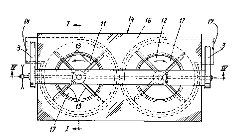
Figure 4 is a cross-section taken on the line IV-IV in
Figure 3;
C

~ t9 ~
Figure S is a plan view of the apparatus shown in
figure 2;
Figure 6 is a cross-section taken on the line VI-VI
in figure 5; and
Figure 7 is a cross section of the supporting beam
that mounts the spreader systems as in figures 2, 5, and 6.
In the drawings, the rear outlet hood of a harvester-
thresher is numbered 1. Two flanges 2 are secured to the
side walls of this hood and holders 3 that are arranged on
these flanges support a hollow beam 4. Within this beam 4
there is a drive shaft 5 that is so supported that it can be
driven by a sprocket 5a; two bevel gears 6 and 7 are mounted
on the drive shaft 5. These bevel gears 6 and 7 mesh with
the bevel gears 8 and 9 that are fixed on the shaft 10, which
is supported so as to be able to rotate within the walls of
the hollow beam. Discs 11 and 12 are fixed to the shafts
10, there being spreader bars 13 installed on said discs.
The discs 11 and 12, and the spreader bars 13 are each
covered by a housing 14, each of said housings consisting of
a cover 15 at the periphery and a cover 16 on the face end.
It can be seen from figures 1 and 4 that each of the face-
end covers 16 of each housing hasan air-passage gap 17. In
the embodiments shown in figures 1, 3, and 4, both air and
grain-chaff mixture are drawn through these air passages 16
by the spreader bars and then ejected through the discharge

36~
openings 18 and 19 onto the surface of the ground.
Figures 2 and 5 to 7 show another embodiment. This
will only be described to the extent that the form of the
embodiment differs from that shown in figures 1, 3, and 4. It
can be seen, in particular from figures 2 and 6 that the discs
11' are fitted with spreader bars 13' on the side that faces
the incoming grain-chaff mixture and are fitted with additional
air paddles 20 on the other side. The air-passage gap 17' is
associated with the additional air paddles 20, whereas the
spreader bars 13' face the open face side of the housing 14'.
Whereas in figures 1, 3, and 4, the spreader bars 13 also form
the air paddles, in the embodiment that is shown in figures
2 and 5 to 7 there are additional air paddles 20.
The hollow beam 4' that supports the housing 14'
lies on the side of the housing 14' that is opposite the flow
of grain-chaff mixture. As is shown on the left-hand side of
figure 5 and in figure 7, the face-end covering 16' of the
housing 14' is provided with arcuate slots 21, through which
pass the bolts 22 that can be bolted through the brackets 23
that are secured to the hollow beam 4'. This makes it possible
to aim the housing 14' and thereby the discharge openings 19'
as desired.

Dessin représentatif
Une figure unique qui représente un dessin illustrant l'invention.
États administratifs

2024-08-01 : Dans le cadre de la transition vers les Brevets de nouvelle génération (BNG), la base de données sur les brevets canadiens (BDBC) contient désormais un Historique d'événement plus détaillé, qui reproduit le Journal des événements de notre nouvelle solution interne.

Veuillez noter que les événements débutant par « Inactive : » se réfèrent à des événements qui ne sont plus utilisés dans notre nouvelle solution interne.

Pour une meilleure compréhension de l'état de la demande ou brevet qui figure sur cette page, la rubrique Mise en garde , et les descriptions de Brevet , Historique d'événement , Taxes périodiques et Historique des paiements devraient être consultées.

Historique d'événement

Description Date
Inactive : CIB de MCD 2006-03-11
Inactive : Demande ad hoc documentée 1996-03-10
Le délai pour l'annulation est expiré 1995-09-11
Lettre envoyée 1995-03-10
Accordé par délivrance 1992-03-10

Historique d'abandonnement

Il n'y a pas d'historique d'abandonnement

Titulaires au dossier

Les titulaires actuels et antérieures au dossier sont affichés en ordre alphabétique.

Titulaires actuels au dossier
CLAAS OHG
Titulaires antérieures au dossier
FRANZ GLAUBITZ
HORST HARIG
Les propriétaires antérieurs qui ne figurent pas dans la liste des « Propriétaires au dossier » apparaîtront dans d'autres documents au dossier.
Documents

Pour visionner les fichiers sélectionnés, entrer le code reCAPTCHA :


Pour visualiser une image, cliquer sur un lien dans la colonne description du document. Pour télécharger l'image (les images), cliquer l'une ou plusieurs cases à cocher dans la première colonne et ensuite cliquer sur le bouton "Télécharger sélection en format PDF (archive Zip)" ou le bouton "Télécharger sélection (en un fichier PDF fusionné)".

Liste des documents de brevet publiés et non publiés sur la BDBC .

Si vous avez des difficultés à accéder au contenu, veuillez communiquer avec le Centre de services à la clientèle au 1-866-997-1936, ou envoyer un courriel au Centre de service à la clientèle de l'OPIC.


Description du
Document 
Date
(aaaa-mm-jj) 
Nombre de pages   Taille de l'image (Ko) 
Dessins 1993-10-27 3 84
Revendications 1993-10-27 3 89
Page couverture 1993-10-27 1 12
Abrégé 1993-10-27 1 13
Description 1993-10-27 4 112
Dessin représentatif 2000-08-02 1 19
Taxes 1994-02-09 1 23