Note: Descriptions are shown in the official language in which they were submitted.
1'~969~77
CABLES AND TIRES REINFORCED
BY SAID CABLES
The present invention relates to nonmetallic cables
having utility for reinforcing tires, and to tires that
are reinforced by said cables.
Tires having a reinforcing member disposed radially
outwardly of the belt plies comprising cables oriented
at small angles with respect to the mid-circumferential
plane of the tire have been found to be particularly
durable when subjected to high revolution speeds. Such
a reinforcing member is often referred to as an overlay
ply. An overlay ply can, for example, be interposed
between the radially outermost belt ply and the tread
and comprise one or more wraps having a width which is
about equal to that of the widest of the belt plies.
Alternatively, the overlay ply can consist of two
separate axially spaced apart ply portions either
disposed radially outwardly of the belt such as to
cover the edges of the radially outermost belt ply or
interposed between the belt plies such as to extend
between the edges thereof.
In the following description, the overlay ply will
be described in terms of at least one wrap disposed
between the belt and the tread, but it will become
apparent to a person skilled in the art that problems
encountered in the prior art with single overlay plies
and the solutions that the present invention presents
thereto apply equally to overlay plies c~mprising two
or more wraps or two or more portions as described
above.
The overlay ply is usually applied onto the
unw lcanized tire as a single annular layer disposPd
i2~6g77
radially outwardly of the belts with the two end
portions of the ply slightly overlapping to form a
splice. However, as a result of the expansion of the
tire in the curing mold and as a result of the thermal
contraction of the textile filaments, the stresses in
the cords of the ply are non-uniformly distributed
around the circumference of the tire and slippage
between the overlay ply end portions tends to occur at
their overlap region. This slippage at the overlap
region of the overlay ply generally produces an
undesired distortion on the underlying belts. This, in
turn, can result in an unbalanced portion in the tire
and a reduction in tire uniformity. These undesirable
conditions are aggravated by the vulcanizing of a tire
in a two piece mold rather than a segmented mold.
The degree of nonuniformity displayed by tires
having overlay plies comprising known cables has been
significantly reduced in tires having overlay plies
employing the new cables disclosed herein.
Various aspects of the invention are as follows:
A nonmetallic cable comprising two yarns twisted
together with one another, each of said yarns comprising
a plurality of filaments, with one of said yarns having
a yarn twist of zero before the yarn is incorporated
into a cable and the second yarn having a yarn twist in
the range of 10 turns per inch to 16 turns per inch in a
first rotational direction, said cable having a cable
twist in a second rotational direction that is opposite
to said first direction, and said cable having an
elongation of at least 4% when subjected to a force of
12 Newtons.
A cable comprising two yarns twisted together with
one yarn with each yarn comprising a plurality of
filaments of at least one material selected from the
group consisting of nylon 6 and nylon 6,6, before said
yarns are twisted together with one another one of said
lZ~65~77
yarns has a yarn twist of zero and the other yarn has a
yarn twist in the range of 10 turns per inch to 16
turns per inch in a first rotational direction, said
cable having a cable twist in a second rotational
direction that is opposite to said first rotational
direction, and said cable having an elongation of at
least 4% when subjected to a force of 12 Newtons.
A tire comprising:
(a) at least one carcass ply;
(b) at least one belt ply disposed radially
outwardly of said carcass ply in a crown
portion of the tire; and
(c) a reinforcing member disposed radially
outwardly of said belt ply and comprising at
least one nonmetallic cable disposed at 0 to
20 with respect to a mid-circumferential
plane of the tire, said cable comprising two
yarns twisted together with one another, each
of said yarns comprising a plurality of
filaments, before said yarns are twisted
together with one another one of said yarns
has a yarn twist that is at least twice as
large as the yarn twist of the other yarn,
said yarn twists being in opposite rotational
directions from one another, said cable having
a cable twist that is opposite in rotational
direction to the twist of the yarn having the
larger of the two yarn twists, the resultant
twist of said yarns in said cable differing
from one another by a factor of at least two
and said cable having an elongation of at
least 4% when subjected to a force of 12
Newtons.
A tire comprising:
~a) at least one carcass ply;
(b) at least one belt ply disposed radially
outwardly of said carcass ply in a crown
portion of the tire; and
(c) a reinforcing member disposed radially
S outwardly of said belt ply and comprising at
least one nonmetallic cable disposed at 0 to
20 with respect to a mid-circumferential
plane of the tire, said cable comprising two
yarns twisted together with one another, each
of said yarns comprising a plurality of
filaments, before said yarns are twisted
together with one another one of said yarns
has a yarn twist of zero and the second yarn
has a yarn twist in a first rotational
direction, said cable having a cable twist in
a second rotational direction that is opposite
to said first rotational direction, and said
cable having an elongation of 4% when
subjected to a force of 12 Newtons.
A tire comprising:
(a) at least one carcass ply;
(b) at least one belt ply disposed radially
outwardly of said carcass ply in a crown
portion of the tire; and
(c) a reinforcing member disposed radially
outwardly of said belt ply and comprising at
least one nonmetallic cable disposed at 0 to
20 with respect to a mid-circumferential
plane of the tire, said cable comprising two
yarns twisted tsgether with one another with
each yarn comprising a plurality of filaments
of at least one material selected from the
group consisting of nylon 6 and nylon 6,6,
before said yarns are twisted together with
one another one of said yarns has a yarn twist
of zero and said second yarn has a yarn twist
lZ9~977
that is at least 10 turns per inch in a first
rotational direction that is opposite to said
first rotational direction, said cable having
a cable twist in a rotational direction, and
said cable having an elongation of at least 4%
when subjected to a force of 12 Newtons.
A nonmetallic cable comprising two yarns twisted
together with one another, each of said yarns comprising
a plurality of filaments, said cable being manufactured
by the process consisting of the steps of imparting a
yarn twist to each of said yarns such that before said
yarns are twisted together with one another one of said
yarns has a yarn twist that is at least twice as large
as the yarn twist of the other yarn, said yarn twists
being in opposite rotational directions from one
another, and then twisting both of said yarns together
with one another to form a cable having a cable twist
that is opposite in rotational direction to the twist of
the yarn having the larger of the two yarn twists, the
resultant twist of said yarns in said cable differing
from one another by a factor of at least two and said
cable having an elongation of at least 4% when subjected
to a force of 12 Newtons.
A cable comprising two yarns twisted together with
one another with each yarn comprising a plurality of
filaments of at least one material selected from the
group consisting of nylon 6 and nylon 6,6, said cable
being manufactured by the process consisting of the
steps of imparting a yarn twist to each of said yarns
such that before said yarns are twisted together with
one another one of said yarns has a yarn twist of
greater than zero but not more than 5 turns per inch in
a first rotational direction and said second yarn has a
yarn twist that is at least three times the yarn twist
of the first yarn in a second rotational direction, and
5a
then twisting said yarns with said yarn twists together
with one another to form a cable having a cable twist in
said first direction, the resultant twist of said yarns
in said cable differing from one another by a factor of
at least two and said cable having an elongation of at
least 4% when subjected to a force of 12 Newtons.
A tire comprising:
(a) at least one carcass ply;
(b) at least one belt ply disposed radially
outwardly of said carcass ply in a crown
portion of the tires; and
(c) a reinforcing member disposed radially
outwardly of said belt ply and comprising at
least one nonmetallic cable disposed at 0 to
20 with respect to a mid-circumferential
plane of the tire, said cable comprising two
yarns twisted together with one another with
each yarn comprising a plurality of filaments
of at least one material selected from the
group consisting of nylon 6 and nylon 6,6,
said cable being manufactured by the process
consisting of the steps of imparting a yarn
twist to each of said yarns, one of said yarns
having a yarn twist of greater than zero but
not more than 5 turns per inch in a first
rotational direction and said second yarn
having a yarn twist that is at least three
times the yarn twist of the first yarn in a
second rotational direction, and then
twisting said yarns having said yarn twists
together with one another to form a cable
having a cable twist in said first rotational
direction, the resultant twist of said yarns
in said cable differing from one another buy a
factor of at least two and said cable having
an elongation of at least 4% when subjected to
a force of 12 Newtons.
lZ~77
5b
The present invention may best be understood by
referring to the following detailed description, in
conjunction with the accompanying drawings in which:
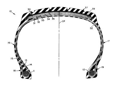
Fig. 1 is a cross-sectional view of a tire taken in
a plane that contains the tire's axis of rotation;
Fig. 2 is an enlarged view of a cable according to
the present invention;
Fig. 3 and 4 are schematic representations of
cross-sections of cables according to the invention; and
Fig. 5 is a graph showing stress-strain
characteristics of a prior art cable and a cable
according to the invention.
With reference to Fig. 1, there is shown an example
of a tire 10 according to the invention which has a
12~6~'~7
pair of substantially inextensible annular bead cores
11,12 which are axia~ly spaced apart with one or more
carcass plies 13,14,15 extending between the bead
cores.
As used herein and in the claims, the terms "axial"
and "axially" refer to directions which are parallel to
the axis of rotation of a tire, and the terms "radial"
and "radially" refer to directions that are
perpendicular to the axis of rotation of the tire.
Each of the carcass plies 13,14,15 comprises a
plurality of cables oriented at 60 to 90, preferably
75 to 90, with respect to a mid-circumferential plane
CP of the tire. Put another way, a tire in accordance
with the present invention is commonly referred to as a
radial ply tire. As used herein and in the claims, the
"mid-circumferential plane" of a tire is a plane that
is perpendicular to the axis of rotation of the tire
and is located midway between the sidewalls of a tire
when the tire is not subjected to any load. A turn-up
carcass ply 13,14 is a ply which is folded axially and
radially outwardly about each of the bead cores 11,12
and a turn-down carcass ply 15 is a ply which is folded
radially and axially inwardly about each of the bead
cores 11,12. It is understood that the present
invention applies to tires having any number of
turn-down, or turn-up, or both turn-down and turn-up
carcass plies of any suitable material.
If a tire is o the tubeless variety, a
substantially air impervious layer 52 is disposed
inwardly of all of the carcass plies 13,14,15. If
desired, a barrier ply of a suitable material (not
shown~ is disposed between the air impervious layer 52
and the innermost carcass ply 13. The barrier ply
functions to separate the air impervious layer from the
12969'~7
elastomeric material in which the cables of the carcass
ply 13 a`re embedded.
A belt structure 30 comprising two or more belt
plies 31-35 is disposed radially outwardly of all of
the carcass plies 13,14,lS in a crown region of the
tire. A ground engaging tread portion 37 is disposed
radially outwardly of the belt structure 30, and a
sidewall portion 16,17 extends radially inwardly from
each axial edge of the tread portion to a respective
bead portion 18,19. In the example illustrated in
Fig. 1, one of the belt plies 31 is folded and the
remainder of the belt plies 32-35 are unfolded. It
is understood that the particular belt structure
illustrated in Fig. 1 and described herein is merely
an example of a tire according to the invention and
that a tire designer may employ any arrangement of
folded or unfolded belt plies in accordance with the
performance requirements of a particular tire while
still practicing the present invention.
A reinforcing member 39 is disposed radially
outwardly of a belt ply, and preferably radially
outwardly of the entire belt structure 30, in a crown
portion of the tire. The reinforcing member comprises
at least one nonmetallic cable disposed at 0 to 20
with respect to the mid-circumferential plane CP of the
tire. As used herein, a "nonmetallic" cable is
understood not to contain any metallic filaments.
With reference to Fig. 2, a cable 20 according to
the invention comprises two yarns 21,22, each of which
comprises a plurality of filaments 23. In accordance
with one embodiment of the invention, one of the yarns
21,22 has a yarn twist that is at least twice as large
- as the yarn twist of the other yarn 21,22, and the
cable 20 has a cable twist that is opposite in
lZ~3~377
direction to the twist of the yarn 21,22 having the
larger of the two yarn twists. In accordance with
another embodiment of the invention, one of the yarns
21,22 has a yarn twist of zero and the second yarn
21,22 has a yarn twist in a first direction, and the
cable 20 has a cable twist in a second direction that
is opposite to said first direction.
The concept of twist can be explained by referring
to Figs. 3 and 4. In a cable 20 used in practicing the
present invention, each of the yarns 21,22 has its
component filaments 23 twisted together a given number
of turns per unit of length of the yarn (typically, the
unit o~ length is 1 inch or 1 meter) and the yarns are
twisted together a given number of turns p~r unit of
length of the cable. Twist dimensions used herein are
in inches. As used herein, the direction of twist
refers to the direction of slope of the spirals of a
yarn or cable when it is held vertically. If the slope
of the spirals conforms in direction to the slope of
the letter "S", then the twist is called "S" or "left
hand". If the slope of the spirals conforms to the
: ælope of the letter "Z", then the slope is called "Z"
or "right hand". As used herein an "S" or "left hand"
twist direction is understood to be an opposite
directiQn from a "Z" or "right hand twist". "Yarn
twist" is understood to mean the twist imparted to a
yarn before the yarn is incorporated into a cable, and
"cable twist" is understood to mean the twist imparted
to two or more yarns when they are twisted together
with one another to form a cable.
It is important to note that as used herein all
references ~o denier, of both yarns and cables, relate
to the denier of a yarn, or yarns, before any twist is
imparted to the yarn(s~. Of course, when a twist is
12''36~3~7
imparted to a yarn or cable, the actual weight per unit
of length increases. "Denier" is understood to mean
the weight in grams of 9,000 meters of a yarn before
the yarn has any twist imparted thereto. For example,
a 1500/3 cable comprises three yarns each of which has
a denier of 1500 before any twist at all is imparted
thereto, such that the cable denier is 4500.
If, for example only, with references to Fig. 3 the
filaments of one of the yarns 22 are twisted together
in the direction indicated by arrow 22A at 4 turns per
inch (157 turns per meter) and the filaments of the
other yarn 21 are twisted together in the direction
indicated by arrow 21A at 9 turns per inch (354 turns
per meter), the two yarns 21,22 will have yarn twists
of unequal values and in opposite directions. The
yarns 21,22 are then twisted together in the direction
indicated by arrow 20A at 12 turns per inch (472 turns-
per meter) so that the cable has a cable twist 20A that
is opposite in ~irection to the twist 21A of the yarn
21 having the larger of the two yarn twists. During
the cable twisting operation, the twist in the yarns
will be altered, but the resultant twist in the yarns
will not be equal to one another. As used herein
"resultant yarn twist" is understood to mean the twist
a yarn has after it has been incorporated into a cable.
If, for example only, with reference to Fig. 4, the
- filaments of one of the yarns 22 have no twist imparted
thereto before the cable twisting operation the yarn 22
will have a yarn twist of zero. If the other yarn 21
has a yarn twist of 14 turns per inch (551 turns per
meter) in a direction indicated by arrow 21A, and then
the yarns 21,22 are twisted together in the direction
indicated by arrow 20A, which is opposite to direction
21A, at 13 turns per inch ~512 turns per meter) the
lZ~i977
-10-
resultant twists in the yarn will be in opposite
directions and will have different values.
When a tire is vulcanized in a two piece mold, the
circumference of the tire increases about 4~ as the
tire is expanded to fit the mold. Therefore, the force
necessary to cause the cables of the overlay to
elongate 4% is critical. If the force is too large the
overlay will be under such a high tension that the
adjacent belt ply will be distorted. Such a condition
causes nonuniformity in the tire, which will manifest
itself as peak radial run-out values that are outside
of manufactureris tolerances.
It is recognized in the tire art that the
undesirable results discussed above can be minimized if
the force on the overlay cables during the process of
shaping the tire into a mold is not greater than 12
Newtons. Therefore, a cable according to the invention
has an elongation of 4% when subjected to a force of
not greater than 12 Newtons.
Fig. 5 is a graph showing the stress-strain curves
of a cable according to the invention and a cable of
the type currently being used in overlays. The "prior
art cord" or cable is 840/2 Nylon 6,6 with a balanced
twist of 12Z in each yarn and a cable twist of 12S, so
- 25 that the resultant twist in the yarns are substantially
equal to one another, such a cable is often referred to
as being a balanced cable. The "new cord" or cable is
a cable according to a preferred embodiment of the
invention comprising 840/2 Nylon 6J6, one yarn having a
yarn twist of zero, one yarn having a yarn twist of 14Z
and the cable twist being 13S. It is clear from the
graph that changing the twist of the yarns and cable as
disclosed herein can have a significant effect upon the
physical properties of the cable.
6~377
Tires have been manufactured under controlled
conditions using cables of the types described in the
preceding paragraph, the overlays in these tires
comprised one complete wrap of side by side cables,
with a lapped splice. In all other respects, the tire
constructions were substantially the same. Tires
having an overlay comprising the prior art cables had
the splice length reduced by about 1/3 from the as
built state to the w lcanized state, while the tires
with the cables according to the invention had splice
lengths reduced by only about 1/5 from the as built
state to the w lcanized state. When these same tires
were evaluated for uniformity characteristics (Radial
- Force Variation, Lateral Force Variation, Radial
Run-Out and Lateral Run-Out), the tires containing
overlays with cables according to the invention were
better in every respect than the tires containing the
prior art cables in their overlays. These tires were
also X-rayed to determine the distortion in width of
the belt ply adjacent to the overlay at the overlay
splice. In each instance, the distortion was less in
the tires that contained cables according to the
invention. The only area in which the tires were
tested and the tires containing the prior art cables in
their overlays were slightly better was in high speed
durability testing, but the tires containing the new
cables were still within an acceptable range of
results. In all o-ther respects, the tires were-
substantially equal.
While at the time this application is being filed
applicant's believe that cables according to the
invention could comprise any suitable material, it is
preferred that the yarns of the cable comprise at least
one material selected from the group consisting of:
1296;977
nylon 6, nylon 6,6, rayon, polyester and aramid. More
preferably, the yarns consist of nylon 6 or nylon 6,6
and most preferably nylon 6,6.
In order to provide cables which are fine tuned for
a particular tire one yarn of a cable may comprise a
first material while the other yarn comprises a second
material. For example, one yarn could comprise 840
denier nylon 6 and the other yarn could comprise 840
denier nylon 6,6.
Another way in which cables according to the
invention can be fine tuned is to have both yarns
comprise the same material with the denier of one yarn
being greater than the denier of the other yarn. For
example, one yarn could comprise 420 denier nylon 6,6
and the other yarn could comprise 840 denier nylon 6,6,
or one yarn could comrpise 500 denier polyester and the
other yarn could comprise 1,000 denier polyester.
Yet another way in which cables according to the
- invention can be fine tuned is to have both yarns
comprise the same material, but in one of the yarns,
the material is altered to have different physical
properties from the material in the other yarn. For
example, one yarn could comprise 500 denier polyester
having high shrinkage properties and the other yarn
could comprise 500 denier polyester having low
~ shrinkage properties.
In a cable according to the invention wherein both
- of the yarns have a yarn twist that is greater than
zero, the larger of the two yarn twists should be at
least twice as large, and preferably at least three
times as large, as the lesser of the two yarn twists.
If each of the two yarns comprises nylon 6 or nylon
6,6, it is preferred that the smaller of the two yarn
twists be not greater than 5 turns per inch (197 turns
~7 7
-13-
per meter) and that the yarn twist of the second yarn
be àt least three times the yarn twist of the second
yarn. If each of the two yarns comprises nylon 6 or
nylon 6,6 and one of the yarns has a yarn twist of
zero, then it is preferred that the second yarn have a
yarn twist of at least 10 turns per inch (394 turns per
meter), and most preferably a yarn twist in the range
of 10 turns per inch (394 turns per meter) to 16 turns
per inch (630 turns per meter). Most preferably, the
cable twist of a cable according to the invention is
not equal to the yarn twist of either of the yarns of
the cable.
It is understood that a tire according to the
invention may have a reinforcing member disposed
radially outwardly of a belt ply with the reinforcing
member (overlay) comprising cables according to any of
the foregoing embodiments disposed at 0 to 20 with
respect to a mid-circumferential plane of the tire.
While certain representative embodiments and
details have been presented for the purpose of
illustrating the invention, it will be apparent to
those skilled in the art that various changes and
- modifications may be made therein without departing
from the spirit or scope of the invention.