Language selection

Search

Patent 1297414 Summary

Third-party information liability

Some of the information on this Web page has been provided by external sources. The Government of Canada is not responsible for the accuracy, reliability or currency of the information supplied by external sources. Users wishing to rely upon this information should consult directly with the source of the information. Content provided by external sources is not subject to official languages, privacy and accessibility requirements.

Claims and Abstract availability

Any discrepancies in the text and image of the Claims and Abstract are due to differing posting times. Text of the Claims and Abstract are posted:

  • At the time the application is open to public inspection;
  • At the time of issue of the patent (grant).
(12) Patent: (11) CA 1297414
(21) Application Number: 563192
(54) English Title: SILENCER
(54) French Title: SILENCIEUX
Status: Deemed expired
Bibliographic Data
(52) Canadian Patent Classification (CPC):
  • 172/25
(51) International Patent Classification (IPC):
  • F01N 1/14 (2006.01)
  • F01N 13/00 (2010.01)
  • F01N 13/18 (2010.01)
  • F01N 3/05 (2006.01)
  • F01N 3/06 (2006.01)
  • F02B 63/02 (2006.01)
  • F01N 1/08 (2006.01)
(72) Inventors :
  • GRANATH, HAKAN ANDERS (Sweden)
  • PETTERSSON, BROR GORAN GUNNAR (Sweden)
(73) Owners :
  • AKTIEBOLAGET ELECTROLUX (Sweden)
(71) Applicants :
(74) Agent: FETHERSTONHAUGH & CO.
(74) Associate agent:
(45) Issued: 1992-03-17
(22) Filed Date: 1988-03-31
Availability of licence: N/A
(25) Language of filing: English

Patent Cooperation Treaty (PCT): No

(30) Application Priority Data:
Application No. Country/Territory Date
8701562-4 Sweden 1987-04-14

Abstracts

English Abstract


A B S T R A C T


The silencer according to the invention contains two chambers (10,11)
separated by a partition wall (14) and includes also a guide plate (25) guiding
cooling air from a fan (27) through a channel (26) in which recesses (23) from
one chamber terminate. By means of an ejecting function, then being formed,
exhaust gases are evacuated into the channel and mixed with the cooling air
to a lower temperature.


Claims

Note: Claims are shown in the official language in which they were submitted.


The embodiments of the invention in which an exclusive
property or privilege is claimed are defined as follows:

1. A silencer for an internal combustion engine of a portable
engine-driven tool, said silencer being divided in two chambers
formed by a pair of metallic shells, said metallic shells forming
a joint defined by a pair of flanges in overlapping relationship,
a first one of said flanges being turned inwards and a second one
of said flanges being turned outwards to define a gap extending
along at least a portion of the periphery of said silencer, the
first flange including recesses therein to establish a fluid
communication between the chamber of the silencer adjoining said
first flange and the environment.

2. Silencer according to claim 1, further comprising a guide
plate over said joint in at least a portion where said recesses
have been provided, said guide plate forming a channel together
with the outside of the metallic shell forming the chamber
adjoining said first flange.

3. Silencer according to claim 2, wherein said guide plate
extends from the said joint to the nearest positioned corner of
the shell, extending around said corner.

4. Silencer according to claim 1, wherein said chambers are
divided by a partition wall including a passage provided with a
metal wire net.

5. Silencer according to claim 2, wherein the silencer forms
part of a cooling system of the internal combustion engine, the
inlet to said channel being directed counterwise to the cooling
air flow of the cooling system.


Description

Note: Descriptions are shown in the official language in which they were submitted.


* ~ iL L~


The present invention relates to a silencer for small
engines in portable engine-driven tools, e.y. clearing saws.
When using engines in the open air there is a ris~ of
igniting inflammable material close to the gas outlet of the
engine, if the exhaust gases are permitted to contain glowing
particles which might cause fire. In order to reduce the fire
risk stipulations have been issued stating the requirements for
a~proval of such engines for use in woods and fields. Thus, a
silencer should contain a spark trap or the like and have an
arrangement for lowering the gas temperature. The simplest form
of a spark trap is a net in a passage opening between different
chambers of the silencer while, on the other hand, the
arrangement for a temperature reduc~ion can be much more
complicated. Such a complicated arran~Jement is known, for
instance, from the German publication DE-OS 29 29 965.
By the present invention an arrangement of silencer is
presented where, by means of an ejector function, the e~haust
gases are ejected from a silencer chamber through a gap and mixed
up with cooling air from the engine to a lower temperature.
Besides the gap mentioned a guide shield is used which, on one
hand, catches the cooling air and on the other hand forms an
outlet for the gas mixture at a lower temperature.
In a broad aspect, the invention comprises a silencer for
an internal combustion engine of a portable engine-driven tool,
the silencer being divided in two chambers formed by a pair of
metallic shells, the metallic shells forming a joint defined by
a pair of flanges in overlapping relationship, a first one of the
flanges being turned inwards and a second one of the flanges
being turned outwards to define a gap extending along at least
a portion of the periphery of the silencer, the first flange
including recesses therein to establish a fluid communication
between the chamber of the silencer adjoining the first flange
and the environment.
~ n embodiment of the invention is described in the following
with reference to the accompanying dxawings, which show in:
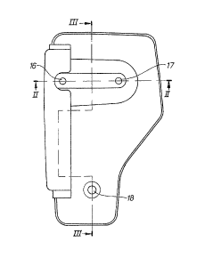
Fig. 1 a vertical projection of the silencer according
to the invention;

- la -

Fig. 2 a horizontal sectlon of the silencer at the line
II - II in Fig. 1;
Fig. 3 a side projection of the silencer with cross
section at III - III in Fig. 1;
Fig. 4 the location of the silencer ln a chain saw with
a cooling fan and a way for cooling air.
Fig. 1 showY a complete silencer in a preferred embodiment,
suitable to be used in a chain saw. The silencer has two
chambers 10,11 which are principally located in a pair of metal
shells 12 and 13, respectively, put together into a unit.
Between the chambers there is a partition wall 14 through which
the chambers communicate via a passage opening 15. The silencer
is mounted by means of three through screws in the holes 16, 17,
18 onto an engine body 19 (Flg. 4). The exhaust gases then enter
into the ~ 7

7~
chamber 10 through a gate 20 between the two upper holes 16 17. The metal
shells are kept together by the screws which provide when being tightened a
compact connection between the silencer and the exhaust gate of the engine.
The joint between the metal shells has a special shaping according to
Fig. ~. On the outer edge of tl e sllell 12 a flar ge 21 ha~ becn cElrried out
which surrounds the whole shell. The flange overlaps the lower edge of the
shell 14 providing a flange 22 turned inwards. In this flange there are some
recesses 23 made along a long side of the shell 13. Through these recesses
chamber 11 is connected to the environment so that the exhaust gases
thereby can leave the chamber. Thanks to parallelism between the
flanges 21, 22 the gas is guided a way which leads along the outside of the
shell 13 ~along the outlet arrow 24).
The indicated way along the arrow 24 has also been created by means o~
a guide plate 25 located outside the corner of the shell 13 and forming in that
way a channel 26 with limit surfaces in the guide plate and the outside oF the
shell. As appears in Fig. 4 the engine has a cooling fan 27 which runs an air
current from an inlet opening 2~ tllrougll an engine room 29, limited by a
casing 3û to an outlet opetling 31 close to tt e silencer. Prior to the outlet
through the opening the air passes the silencer and a part of the air current
takes its way through the channel 26 (see arrow 32 Fig. 2). The air through
the channel proYides an ejecting function on the exhaust outlet along the
arrow 24 and decreases the resistance in the exhaust channel. Thanks to the
bending of the channel round the corner of the silencer a turbulence is
created in it which acts for a good mixture of gas and air.
The spark trap mentioned in the introduction consists in the example
described of a wire net 33 in the passage opening 15. Thanks to the net the
glowing particles called sparks will remain in the chamber 10. Instead of the
recesses 23 there will probably also be a possibility o~ carrying out inward
bends in the flange 22 through which the exhaust gases may escape.
Representative Drawing
A single figure which represents the drawing illustrating the invention.
Administrative Status

For a clearer understanding of the status of the application/patent presented on this page, the site Disclaimer , as well as the definitions for Patent , Administrative Status , Maintenance Fee  and Payment History  should be consulted.

Administrative Status

Title Date
Forecasted Issue Date 1992-03-17
(22) Filed 1988-03-31
(45) Issued 1992-03-17
Deemed Expired 2003-03-17

Abandonment History

There is no abandonment history.

Payment History

Fee Type Anniversary Year Due Date Amount Paid Paid Date
Application Fee $0.00 1988-03-31
Registration of a document - section 124 $0.00 1988-08-03
Maintenance Fee - Patent - Old Act 2 1994-03-17 $100.00 1994-02-22
Maintenance Fee - Patent - Old Act 3 1995-03-17 $100.00 1995-02-17
Maintenance Fee - Patent - Old Act 4 1996-03-18 $100.00 1996-02-20
Maintenance Fee - Patent - Old Act 5 1997-03-17 $150.00 1997-02-17
Maintenance Fee - Patent - Old Act 6 1998-03-17 $150.00 1998-02-19
Maintenance Fee - Patent - Old Act 7 1999-03-17 $150.00 1999-02-17
Maintenance Fee - Patent - Old Act 8 2000-03-17 $150.00 2000-02-17
Maintenance Fee - Patent - Old Act 9 2001-03-19 $150.00 2001-02-19
Owners on Record

Note: Records showing the ownership history in alphabetical order.

Current Owners on Record
AKTIEBOLAGET ELECTROLUX
Past Owners on Record
GRANATH, HAKAN ANDERS
PETTERSSON, BROR GORAN GUNNAR
Past Owners that do not appear in the "Owners on Record" listing will appear in other documentation within the application.
Documents

To view selected files, please enter reCAPTCHA code :


To view images, click a link in the Document Description column. To download the documents, select one or more checkboxes in the first column and then click the "Download Selected in PDF format (Zip Archive)" or the "Download Selected as Single PDF" button.

List of published and non-published patent-specific documents on the CPD .

If you have any difficulty accessing content, you can call the Client Service Centre at 1-866-997-1936 or send them an e-mail at CIPO Client Service Centre.


Document
Description 
Date
(yyyy-mm-dd) 
Number of pages   Size of Image (KB) 
Representative Drawing 2002-01-28 1 5
Drawings 1993-10-27 2 64
Claims 1993-10-27 1 41
Abstract 1993-10-27 1 12
Cover Page 1993-10-27 1 15
Description 1993-10-27 3 124
Correspondence 2000-02-10 1 36
Fees 1997-02-17 1 75
Fees 1996-02-20 1 65
Fees 1995-02-17 1 79
Fees 1994-02-22 1 75